| SUBMARINES SUBMERSIBLES ROVS & SUB-SEA EQUIPMENT |
Silvercrest Submarines Newsletter (05).
Silvercrest Submarines can arrange Submarine and Rov Maintenance, also Pilot Training courses for purchasers. Submersible Refit and Certification programmes. Whatever your underwater vehicle requirements, just ask us and we will support you. Further information available on request.

Back from a great
Dive off
Jamaica.
CBS journalist’s nightmare dive to the Titanic
The actual dive getting down to the Titanic shipwreck was full of hocus-pocus reported that the dive was initially postponed due to the size of the waves and a consolation dive to the Continental Shelf was also scrubbed at 37 feet under as something went wrong with the platform the sub detaches from at about 30 feet. Days later they tried to reach the Titanic again. Pogue explained there was no GPS underwater, so the surface ship is tasked with guiding the sub to the shipwreck by sending text messages.“But on this dive, communications somehow broke down. The sub never found the wreck,” Pogue explained. On a third attempt on their last day at sea, they had a successful dive where they saw the Titanic at the bottom of the ocean. Not only does the Titan not have GPS underwater, the hatch is bolted shut from the outside. And according to Pogue there is no other way out. He explained to BBC on Tuesday, there was no escape pod and the sub needed to get to the surface. “It’s get to the surface or die,” he said. He understood the sub had seven different ways to resurface and that it was “really concerning” none of these had worked so far.Titanic expedition leader, @gmichaelharris, says more people have been to outer space than the depth of the ocean that the missing Titanic tour submarine is. The vessel has a range of 96 hours for a crew of five, and US Coast Guard Rear Admiral John Mauger said Monday afternoon, local time, he believed it still had 70 or more hours of remaining oxygen. Former US Coast Guardsman John Mixson said it was a “dire situation”.“It’s hard to say, whenever you just lose total communications in a situation like that, what actually happened until you find the vessel,” Mr Mixson told Fox News. “This isn’t a common occurrence at all.”“Obviously, something very rapid and very tragic took place.”He added that there was still hope to locate survivors given at this point it was still a search and rescue mission. Among those on board the Titan is British billionaire Hamish Harding, chief executive of Action Aviation in Dubai.“I am proud to finally announce that I joined OceanGate Expeditions for their RMS TITANIC Mission as a mission specialist on the sub going down to the Titanic,” he wrote on social media.“Due to the worst winter in Newfoundland in 40 years, this mission is likely to be the first and only manned mission to the Titanic in 2023,” the 58-year-old added. Tickets for the expedition cost $USD250,000 ($367,000) per person. In a statement quoted by CBS News and other media outlets, OceanGate Expeditions said: “Our entire focus is on the crew members in the submersible and their families.”The US Coast Guard has launched two C-130 planes to survey the surface, while Canada has deployed aircraft “which utilizes sonar technology with buoys,” Chief Petty Officer Robert Simpson told AFP.He said that “after the expected time of return” for the submersible, the OceanGate ship “conducted an initial search and were unable to find anything or any sign of the submarine and they contacted the Coast Guard.”OceanGate said in its statement it was “deeply thankful for the extensive assistance we have received from several government agencies and deep sea companies in our efforts to re-establish contact with the submersible.”Without having studied the craft itself, Alistair Greig, professor of marine engineering at University College London, suggested two possible theories based on images of the vessel published by the press. He said if it had an electrical or communications problem, it could have surfaced and remained floating, “waiting to be found.”Another scenario is the pressure hull was compromised — a leak,” he said in a statement. “Then the prognosis is not good.” While the submersible may still be intact during its dive, “there are very few vessels” able to go to the depth to which the Titan might have travelled.
Whistleblowers warned OceanGate safety issues could prove ‘catastrophic’. Then its Titanic sub imploded
A top employee raised safety concerns five years before the vessel’s catastrophic implosion.
Safety concerns about the Titan submarine that imploded in the depths of the Atlantic Ocean with five people on board have been revealed in a number of scathing reports. The US Coast Guard announced during a Thursday press conference that the missing Titan’s pressure chamber was found among other debris, approximately 1600 feet from the bow of the Titanic on the sea floor by an ROV. In a statement to The Independent, OceanGate — the private company that offers the $250,000-a-seat expedition to the wreck of the Titanic — confirmed that the five passengers aboard the vessel are now believed dead. But before boarding submarines from OceanGate, travellers were warned in a contract that “it has not been approved or certified by any regulatory body, and could result in physical injury, disability, motion trauma, or death”.The disclaimer is part of a long list of concerns regarding the company’s safety record, as its crew remains unaccounted for with air rapidly running out. A lawsuit, a letter from industry leaders, and comments from the company’s own CEO, one of the missing crewmen, all pointed to potential issues with the Titan submersible. In 2018, the company fired David Lochridge, OceanGate’s director of marine operations. They claimed he breached his contract and shared confidential information about its designs with two individuals as well as with the Occupational Safety and Health Administration. However, Mr Lochridge alleged in a wrongful termination suit obtained by The New Republic that he was fired for blowing the whistle about concerning safety issues. According to the suit, Mr Lochridge delivered highly critical updates regarding the ship’s quality control to senior management and OceanGate CEO Stockton Rush, pointing to alleged issues such as “visible flaws” in the ship’s carbon fibre hull, “prevalent flaws” in a scale model, flammable materials onboard, a viewing window not rated for the Titanic’s depth, and key safety documents that were not shared with him. “Now is the time to properly address items that may pose a safety risk to personnel,” he allegedly said at one point. “Verbal communication of the key items I have addressed in my attached document have been dismissed on several occasions, so I feel now I must make this report so there is an official record in place. “The official allegedly pushed for further testing and for outside evaluators like the American Bureau of Shipping to inspect and certify the submarine. He claimed, according to filings obtained by the magazine, that he was fired when he said he wouldn’t authorise manned testing of the sub without scans of the craft’s hull. An attorney for Mr Lochridge, who settled with the company in 2018, said the man has no comment and that “we pray for everyone’s safe return”. That wasn’t the only red flag about the company, which became a media darling for its bold claims about innovating submarine design and bringing tourists to see the famed North Atlantic wreck. In 2018, leaders in the submarine industry wrote a letter from the Marine Technology Society to the company warning of “catastrophic” issues with the submarine’s development. Three dozen signatories including executives, oceanographers, and explorers expressed “unanimous concern”, particularly with the company’s decision not to seek outside evaluation and testing.“While this may demand additional time and expense,” the signatories wrote in the letter, which was obtained by The New York Times. “It is our unanimous view that this validation process by a third party is a critical component in the safeguards that protect all submersible occupants.” In a 2019 blog post, the company defended its decision not to have its sub “classed” by an outside evaluator. “The vast majority of marine (and aviation) accidents are a result of operator error, not mechanical failure,” it reads. “As a result, simply focusing on classing the vessel does not address the operational risks. Maintaining high-level operational safety requires constant, committed effort and a focused corporate culture – two things that OceanGate takes very seriously and that are not assessed during classification.”That same year, Mr Rush, the CEO, told Smithsonian Magazine that submarine regulations were stifling innovation.“There hasn’t been an injury in the commercial sub industry in over 35 years. It’s obscenely safe, because they have all these regulations,” he said. “But it also hasn’t innovated or grown – because they have all these regulations.” The alleged issues didn’t end there. In 2020, the CEO told GeekWire the hull of the submarine was showing signs of “cyclic fatigue”, one of the same technical issues Mr Lochridge allegedly warned about, as the company continued to test the craft, including with a 4,000m deep dive in the Bahamas. As a result, the company temporarily downgraded the Titanic submarine’s hull depth rating to 3,000m, 1,000 less than the Titanic’s depth, according to TechCrunch.Over the next two years, according to the publication, the submarine’s hull, originally built by Spencer Composties, was repaired or rebuilt by aerospace contractors Electroimpact and Janicki Industries. Missing tourist submarine likely ‘stuck’ under Titanic propeller, says Hamish Harding’s friend Electroimpact did not answer specific questions about its reported involvement with the submarine, but company chief operating officer Austin Clark told The Independent via email that“our thoughts and prayers go out to the passengers and their families”.Spencer told TechCrunch its hull wasn’t used on the version of the Titan which went down to the Titanic and went missing. By 2021, the submarine had completed its first trip down to the Titanic. As OceanGate continued to plunge into its Titanic mission, problems continued. A 2022 mission saw the Titan suffer battery issues that required the ship to be manually attached to a key lifting platform, according to court documents Times. Last year, on a visit to the Titanic programme, a CBS News reporter observed the submarine allegedly had “off the shelf components” including lights from Camping World, and that the submarine suffered a communications issue with the ship overseeing its voyage and was lost for nearly three hours underwater. OceanGate Expeditions founder and CEO Stockton Rush, British billionaire Hamish Harding, renowned French diver Paul-Henri Nargeolet, Pakistani businessman Shahzada Dawood and his 19-year-old son Suleman were on board the Titan. All five passengers are presumed dead following the discovery of debris on Thursday. The Coast Guard says that ROVs will remain in place but that it will begin to pull back equipment over the next 48 hours.
The Submarine Visiting The Titanic ‘Instantaneously Imploded’
OceanGate Expeditions now says the five people aboard its Titan submersible vehicle that went missing Sunday are thought to be dead. “We now believe that our CEO Stockton Rush, Shahzada Dawood and his son Suleman Dawood, Hamish Harding, and Paul-Henri Nargeolet, have sadly been lost,” the company said in a statement Thursday. Contact with the sub was lost shortly after beginning its descent from the surface of the Atlantic Ocean to visit the wreckage of the famed Titanic.US Coast Guard Rear Admiral John Mauger confirmed in a Thursday press conference that the search for Titan yielded debris that is “consistent with a catastrophic loss of the pressure chamber.” “A debris field was discovered within the search area by an ROV near the Titanic,” the Coast Guard said in an earlier tweet announcing the press conference. Titan lost contact with the surface less than two hours after beginning its journey on Sunday. It was thought to have about 96 hours worth of oxygen aboard. OceanGate co-founder Guillermo Söhnlein, who left the company years ago, told the British broadcaster in response to the news of the discovered debris: “if there is a failure it would be an instantaneous implosion. If that's what happened that's what would have happened four days ago.”If the hull of the Titan did fail, it may take a long time—if ever—to diagnose what exactly went wrong. But ultimately the cause is certainly the extraordinary forces exerted by the ocean at depth. At a depth of over 2 miles the Titan was subjected to more than 5,500 pounds per square inch (PSI) of pressure. If the sub failed, directly exposing passengers to those kinds of pressures, Roterman says that it would be over very quickly. “If there was any kind of hull breach, the occupants would succumb to the ocean in a near instant.” The pressure we experience from the atmosphere at sea level is a mere 14.7 PSI, or less than three-tenths of a percent of the pressure found at the site of the Titanic shipwreck. “I think it is important to remember that to us humans, the deep sea is a very inhospitable place,”Even the most reliable technology can fail, and therefore accidents will happen. With the growth in deep-sea tourism, we must expect more incidents like this.”
Titanic sub implosion: Was the deep ocean vehicle safe?
The implosion of a submersible touring the deep-sea wreckage of the Titanic, killing all five passengers on board, has prompted questions about the regulations overseeing such voyages — and whether the vehicle itself was safe. On Friday, the company responsible for the tour, OceanGate Expeditions, defended the decisions of its chief executive Stockton Rush, who died on board the submersible. “Stockton was one of the most astute risk managers I’d ever met. He was very risk-averse,” Guillermo Söhnlein, OceanGate’s co-founder, told the news agency Reuters. “He was very committed to safety.”But in the days since the submersible first went missing, passengers have come forward to share their stories of glitches and mishaps on expeditions to the ocean floor. Josh Gates, the host of the TV series Expedition Unknown, shared his experience on board the same submersible, the Titan, that ultimately imploded on Sunday.“Titan did not perform well on my dive,” Gates wrote in a tweet on Wednesday. The Titan, at the time, was preparing for its maiden voyage to the Titanic, which is situated 3.8 kilometres (12,500ft) below the surface of the North Atlantic Ocean. But even in the testing phase, Gates observed cause for alarm. “We had issues with thruster control,” he told US broadcaster NBC’s Today Show on Thursday. “We had issues with the computers aboard. We had issues with comms. I just felt as though the sub needed more time, and it needed more more testing, frankly.”Mike Reiss, a comedy writer for The Simpsons, likewise experienced communication failures during his trips with OceanGate, one of which went down to the Titanic.“I took four different dives with the OceanGate company,” Reiss told ABC News. “And every time they lost communication.”But he was ambivalent about the problems: “That seems to be just something baked into the system. I don’t blame OceanGate. I blame deep water for that.”James Cameron — director of the film Titanic and himself a deep-sea researcher — was more unequivocal in his criticism. In an interview with ABC News, he denounced the carbon-fibre construction of the Titan as “fundamentally flawed”.“Many people in the community were very concerned about this sub,” Cameron said. “And a number of the top players in the deep-submergence engineering community even wrote letters to the company saying that what they were doing was too experimental to carry passengers and it needed to be certified and so on.”The Oscar-winning director drew a parallel between the Titan’s implosion and the cut corners that led to the wreckage of the Titanic itself.“I’m struck by the similarity of the Titanic disaster itself, where the captain was repeatedly warned about ice ahead of his ship, and yet he steamed at full speed,” Cameron said, adding that warnings in both cases “went unheeded”.The Titan submersible began its descent to the ocean floor on June 18. But about an hour and 45 minutes into its voyage, it lost contact with the surface. Officials with the United States Navy later confirmed that underwater acoustic equipment captured an “anomaly consistent with an implosion or explosion” that same day. It notified the US Coast Guard command that day, but as the sound wasn’t definitively the Titan, the search went on. After four days of search-and-rescue operations, the US Coast Guard announced on Thursday that the Titan had suffered a “catastrophic implosion”, leaving debris off the bow of the Titanic. Five people were killed: the CEO Rush, Titanic researcher Paul-Henri Nargeolet, businessman Hamish Harding and father and son Shahzada Dawood and Suleman Dawood.n the wake of the submersible’s initial disappearance, the magazine The New Republic reported on documents from a 2018 breach-of-contract case, wherein OceanGate sued a former employee for disclosing private information. However, the employee, David Lochridge, said he was acting as a whistleblower to ensure the safety of OceanGate passengers and employees. In a counterclaim, Lochridge cited structural cncerns, including “large tears of the carbon” from “constant pressure cycling”.The New Republic also reported that Lochridge faced “hostility” when he requested more information about pressure test results. Duration 00 minutes 59 seconds 00:59itanic sub: What are the key challenges in the search mission? Rush, OceanGate’s late CEO, had addressed questions about Titan’s safety standards in a February 2019 blog post. In it, Rush objected to additional safety standards and regulations for deep-sea travel, calling it a hurdle to technological advancement.“Bringing an outside entity up to speed on every innovation before it is put into real-world testing is anathema to rapid innovation,” Rush had said. He denounced the process of “bringing in outsiders who need to first be educated before being qualified to ‘validate’ any innovations”.Salvatore Mercogliano, a history professor at Campbell University in North Carolina, believes the Titan disaster may be a turning point in deep-sea regulation.“We don’t quite have [safety standards] yet with submersibles,” Mercogliano told The Associated Press. “But I do think that one of the long-lasting implications of this disaster may be seeing that happen.”Just like the Titanic disaster led to regulations requiring adequate lifeboats for all passengers, Mercogliano speculated the Titan implosion could likewise lead to heightened standards. Right now, he said, deep-sea adventures like the Titan voyage are less regulated than commercial trips to space. That, in part, is because they take place in international waters, outside of the legal authority of countries like the US. In addition, the submersible itself is towed to the exploration site, meaning that — even if it passes through US or Canadian water — it is considered cargo, not subject to the same stringent regulations that the boat carrying it might.“There’ll be a time when you won’t think twice about getting on a submersible and going down 13,000ft,” Mercogliano said. “But we’re not there yet.
US Navy submarine forces will be weakened by the Aukus pact
America is struggling to maintain its own sub numbers, and must now hand scarce hulls to Canberra A new three-way naval alliance between the United States, the United Kingdom and Australia promises to massively expand Australia’s undersea firepower – and complicate China’s efforts to dominate the western Pacific Ocean. But the Aukus alliance, which will facilitate the transfer of submarines and nuclear propulsion technology from the United States and the United Kingdom to Australia over the next 30 years, comes at a cost – and not just a financial one. Yes, Canberra could end up shelling out up to $200 billion for eight nuclear-powered attack submarines plus their manpower and industrial support base. For Washington, the main cost is an opportunity cost. To give the Aussies a head-start on their new sub fleet, the US Navy plans to lease to the Australian navy three American-built Virginia-class attack submarines. And that could impede the USN’s plan to grow its own undersea fleet. In short, there are only so many submarines to go around and, at present, no extra industrial capacity for building new anisakis solves at least one problem for each of the countries in the alliance. For Australia, the alliance – which the three governments first announced in 2021 – is a shortcut to a much bigger and more powerful sub fleet. The Royal Australian Navy’s six current subs, diesel-electric Collins-class vessels, displace just 3,500 tons. Compared to a 7,800-ton, nuclear-powered Virginia, a Collins lacks range, speed and torpedo and missile capacity. In particular, diesel boats have very little speed or range when fully submerged and running on battery power. They have to put up “snort” air-intake masts to cover any distance, or run on the surface to cover any distance at speed. Doing either means they can be detected easily on radar. With its future fleet of nuke subs, the RAN can patrol more of the Pacific Ocean with greater firepower – and contribute more to the US Navy’s efforts to deter a Chinese invasion of Taiwan. A nuclear powered submarine can operate fully submerged for months on end at speed, and as such is extremely hard to detect and defend against. For the United States and United Kingdom, Aukus’ most immediate benefit is geographic. Starting in 2027, the US and British fleets will base some of their own submarines in Perth, in western Australia. This will shave hundreds, if not thousands, of miles off American or British subs’ round-trip journey from their current bases to the contested western Pacific. The price the Americans in particular will pay for that new geographical advantage could prove to be too high, however. That’s because the US Navy is already short of submarines – and can’t easily afford to give any of them away. But Aukus commits it to doing so. The ultimate goal of the alliance is to create, in Australia, the industrial capacity to build eight uniquely Australian nuclear-powered submarines based on American and British technology. But those Aussie subs won’t enter service until the 2050s, under the current plan. To bridge the more than 25-year sub gap, the US Navy will lease to the RAN two existing Virginias – and provide the Australian fleet a third Virginia directly off the USA’s submarine production line, which is split between shipyards in Connecticut and Virginia. Giving up three Virginias starting in 2032 could shrink the US sub fleet to a modern low of 46 attack boats (that is, submarines which don’t carry nuclear-tipped strategic ICBMs) at a time when fleet commanders have stated that they need up to 66 subs to deter enemies and win wars. A three-vessel giveaway might not be a problem if the American submarine industrial base had any spare capacity. But it doesn’t. The US Congress usually gives the Navy enough money – $5 billion or so – for two new Virginias every year, but the shipyards average just 1.2 new submarines annually, not even enough to replace old boats as they wear out. The result is a growing backlog of submarine orders on the USN’s books: a backlog that fleet leaders stress gets worse once they factor in the RAN’s appetite for subs under the Aukus framework.“We’re going to have challenges” acquiring submarines on time, Vice Admiral Johnny Wolfe told a US Senate committee in April. The question, for American policymakers, is whether Aukus’ benefits outweigh its burdens. Is more favorable submarine basing – and a stronger Australian fleet – worth a dip in US submarine numbers? The answer, at present, is yes. But that yes seems to hinge on an optimistic assumption: that standing up a new Australian submarine industry will have industrial benefits in the United States (and the United Kingdom) as economies of scale kick in.“Our plan elevates all three nations’ industrial capacity to produce and sustain interoperable nuclear-powered submarines for decades to come,” the White House stated. If three countries are sharing sub tech, workers and expertise, all three should eventually be able to build more and better subs, faster. Right? If that optimism proves to be unfounded, Aukus could amount to a submarine giveaway. A zero-sum transfer of a precious military resource from one country to another – all at a time when that resource is in especially high
demand in the country giving it away.
Scenic submersible delayed surfacing, damaged in Antarctic ice
fast-changing weather saw a Scenic Eclipse submersible abort its Antarctica dive, with its passengers exiting after two hours. In a statement to Seatrade Cruise News, Scenic said, ‘While on a routine excursion operation in Antarctica’s Weddell Sea, and during flat, calm conditions, a katabatic wind event took place. ‘At the time Scenic Eclipse’s submersible, Scenic Neptune, was conducting a dive with guests onboard. ‘As per Scenic safety procedures and [International Association of Antarctica Tour Operators] guidelines, the submersible driver and sea-based team aborted the dive.’Scenic went on to add that the passengers’ delay leaving the submersible was due to ice floes holding up the return to surface. The incident resulted in 'slight' damage to Scenic Neptune’s external tanks. ‘The crew continued to follow the Scenic and IAATO protocols and all guests and crew returned safely to the ship within two hours while the Scenic Neptune submersible was taken into its onboard garage shortly thereafter,’ commented Scenic. The submersible is currently being assessed and Scenic said it will return to service when it is repaired and compliant. According to Scenic, all passengers onboard — and those scheduled on future bookings — have been made aware of the submersible's status. Scenic Eclipse is operating its third season in the Antarctic, during which passengers have also explored by Zodiacs, kayaks and helicopters.
How Safe Are Submarine Tours?
And what’s the difference between a submarine and submersible? All your questions answered following the recent “Titan” wreck. On June 18, an experimental submersible carrying a pilot and four passengers to the wreck of Titanic went missing. After several days of search-and-rescue operations, authorities determined the sub, OceanGate Expedition’s Titan, had suffered a catastrophic implosion, killing all onboard. The incident has understandably caused public concern about the submarine industry at large, and travelers who have booked or are looking to book sub trips might be having second thoughts. But are they warranted? It’s natural to be a little nervous about diving in a submarine or submersible—they are, after all, enclosed environments that take you beneath the sea. But generally speaking, there’s not much cause for worry.“A certified submarine is a lot safer than public perception. Of course, there is risk when boarding a submarine, just as there is risk when you board a plane or get in your car,” says Mckenzie Margarethe, marine naturalist and former submarine copilot for Atlantis Submarines. “However, for most touring submarines, it is uncommon for things to go wrong. Every potentially dangerous scenario has been evaluated, and an emergency plan is developed with the crew training on it regularly to ensure proficiency.”Here’s what you need to know before you book a submarine or submersible tour.
What happened to the “Titan”?
Titan was an experimental submersible designed by OceanGate Expeditions to bring tourists to the Titanic wreck site deep in the North Atlantic Ocean—about 12,500 feet deep. On June 18, during a scheduled dive, the expedition team lost contact with the sub, prompting a multiday search-and-rescue effort by international groups. Debris from the sub was discovered by a remotely operated vehicle (ROV), indicating that the vessel suffered a catastrophic implosion that killed the five people onboard, including OceanGate CEO Stockton Rush, who was piloting the sub. While the investigation is ongoing, it is likely that the sub’s pressure hull, the pressurized compartment for passengers, failed in some way, and the pressure of the surrounding water caused it to implode.
What’s the difference between a submarine and a submersible?
Submarines and submersibles are both underwater craft. Submarines operate independently—they can sail into and out of ports under their own power. Submersibles rely on support ships or platforms for their operations, including transportation to and from dive sites. Titan was a submersible that operated from the support ship Polar Prince, a former Canadian Coast Guard icebreaker. Both submarines and submersibles are used for tourism, with the former popular in island destinations like Hawai‘i and the Caribbean, and the latter more common on expedition cruises.
How safe are submersibles?
When you look at the safety record for classed submersibles, you’ll find that they’re far safer than planes and cars in terms of fatalities.“Classed or accredited human-occupied vehicles (submersibles) have enjoyed an enviable and unblemished safety record for more than 50 years,” says a spokesperson from Triton Submarines, a private submersible designer and manufacturer. “Collectively, classed subs from around the world carry more than 1 million people a year on dives and have done so for almost four decades without a single fatality.”The key here is that those submersibles are all certified, or classed, by third-party classification societies. OceanGate, on the other hand, intentionally did not seek classification for Titan. According to a now-deleted blog post on the company’s website, certification would have taken too long and been “anathema to rapid innovation.”Naval submarines, however, have had numerous fatalities; the U.S. Navy has lost thousands of submariners, mostly due to warfare rather than accidents, but accidents have happened. The Navy has vastly improved submarine safety through the SUBSAFE quality assurance program, which was implemented in 1968 and has since incidents. Legally, there isn’t much oversight at all—there are no international laws governing submarine and submersible operation. But submarine and submersible operators typically do take it upon themselves to certify their vessels for safety, which is often required for insurance purposes. “Naval submarines are certified by the Navy, and private submarines are certified privately,” says Margarethe. Private certification is handled by third-party classification societies, of which there are many around the world, including DNV and Lloyd’s Register. If you plan on taking a sub tour, ensure that your vessel is classed by a society. “Certification requires an arduous, time-consuming, and thorough independent appraisal of every aspect of the design, production, and operation of a human-occupied craft,” says the Triton spokesperson. The process analyzes everything from material selection to system operations, and it includes a dive to the maximum operating depth. Classing isn’t a one-and-done sort of deal; it continues throughout the lifespan of the sub. “Although the class inspection interval varies slightly between the different certification agencies, all of them require annual surveys,” says the Triton spokesperson. “The class society will annually inspect the hull, structure, safety systems, life support equipment, and the functioning of mechanical, fluid, and electrical systems.” Triton subs also undergo more in-depth surveys at longer intervals, with class renewal every five years.
What are your options for rescue if something goes wrong?
Subs have numerous ways to surface, so if one system fails, another will kick in. For example, most subs have a “drop weight” on the bottom, which helps with balance under normal circumstances but can also be jettisoned to cause the sub to surface. But in the event a sub does get stuck at the bottom, most will be at a depth where undersea rescue is possible, whether by divers or another sub. “For the submarine I worked on, we also didn’t go below 150 feet with passengers on board as a safety precaution. This is because in case of emergency, there are vents a scuba diver could access that would fill our ballast with compressed air and bring the submarine to the surface,” says Margarethe. By contrast, Titan was diving to 12,500 feet, the depth of the Titanic wreck. One thing to consider, however, is the location in which you’re diving. A number of new expedition ships carry submersibles, which can be deployed in remote and sometimes dangerous environments like Antarctica. In these remote locations, rescue may be much more difficult, given how long it might take rescue crews to arrive or other variables like sea ice.
Should you take a sub tour?
Sub tours offer a perspective of the ocean that most people don’t get to see, and so long as the operator adheres to proper protocols such as classing and regular inspection, they’re a safe way to witness all sorts of sea life. Of course, there’s always some level of risk involved, particularly in remote environments, which is a judgment call you’ll need to make for yourself. But there are benefits to underwater tourism. “You have a tour guide that can tell you about everything you’re seeing and help you develop a connection with the water,” says Margarethe. “I believe it’s important we foster a connection with the water in as many people as possible, seeing as it makes up the majority of our planet and desperately needs our help and attention.”I took my first submarine tour on a family vacation to the U.S. Virgin Islands when I was a child; we booked seats on an Atlantis Submarine vessel. Admittedly, I didn’t pay much attention to the operational details, but I do recall being mesmerized not only by the flurry of sea life around us but also by the change in color perception as the water absorbs different wavelengths of light the deeper you go. Atlantis subs fit several dozen passengers who can look out of viewports that run the length of the vessel. Because the sub is so large—or perhaps because I was so small at the time—I didn’t feel particularly claustrophobic. Last year, I made my second dive, but this time in Antarctica. The luxury expedition ship Scenic Eclipse has a submersible named Scenic Neptune that carries six passengers plus the pilot, with the passengers seated in two large acrylic spheres that provide 280-degree views. Though the sub was far smaller than the Atlantis sub, these spheres made it feel rather spacious. The only claustrophobia-inducing moment is climbing through the narrow hatch and down the ladder. The sea life in Antarctica is, of course, vastly different than what you’d see in the Caribbean. But knowing that this underwater world is so infrequently seen by “normal” people like me, I was completely captivated by all signs of life, from tiny krill to massive sea sponges. I was, however, a touch nervous to make the dive. Knowing how unpredictable conditions can be in Antarctica from a previous voyage, I worried that something could go wrong. Though my 45-minute dive went off without a hitch, Scenic Neptune did have an incident in November 2022; a powerful weather phenomenon called katabatic winds pushed ice floes over the sub, damaging it slightly, and keeping guests underwater for a couple of hours. All passengers and crew returned to the ship safely.
Questions to ask your submarine tour provider
If you’re nervous about booking a sub tour, here are some questions you can ask your operator to address your concerns.
Is the sub classed and by whom?
Classification by a third-party is a crucial safety measure in the private sub industry.
How often do you inspect the sub?
Subs should be inspected between each dive.
What is the maximum depth the sub can dive to, and how deep will we go on our dive?
Most submarine tour operators will not dive to their subs’ maximum depths—and that’s a good thing. Better safe than sorry.
How long can the sub stay underwater in an emergency situation?
Find out about the oxygen supply onboard, as well as stores of food and water.
If the sub gets stuck on the seafloor, how will we be rescued?
Tour operators should be able to answer this question with ease, as they should have numerous safety plans in place.
Does the sub have an emergency beacon that will broadcast our location in an emergency?
Most submarine tour operators will have an escort vessel on the surface to monitor the sub closely. But it wouldn’t hurt for the sub to have an emergency position-indicating radio beacon (EPIRB) or submarine emergency position-indicating radio beacon (SEPIRB) onboard, both of which will broadcast the sub’s location in an emergency (the former works on the surface, and the latter works underwater).
Chilling warnings submarine CEO ignored as he was told 'you'll kill someone'
Neither experts nor friends could get through to OceanGate CEO Stockton Rush when they expressed their concerns over the safety of Titan, the submersible that imploded on June 18. Rob McCallum was one of several people to express concerns to OceanGate CEO Stockton Rush over Titan's |He was first warned as early as 2015, then again in 2017, then again in 2018, then yet again in 2019.But Stockton Rush didn't listen to experts or even his friends who told him that Titan, his company OceanGate's deep-sea submersible, was unsafe. The vessel historically imploded during a voyage to the Titanic on June 18, killing five men including Rush, sparking a more-than-two-day manhunt and then, recovery effort. Rob McCallum was first approached by Rush in 2015, when the OceanGate CEO asked him to run his Titanic operation, he told Yorker. The veteran submersibles expert had ventured down to the shipwreck several times, even taking tourists with him, using classed Russian submarines built to withstand the immense 6,000 PSI pressure at the sea floor. OceanGate CEO Stockton Rush ignored warnings from experts and friends about Titan's safety Rush wanted the EYOS Expeditions co-founder to lead the charge because of his experience, and he wanted McCallum to help him "go a step further and build a vehicle specifically for this multi-passenger expedition."But when McCallum visited OceanGate's workshop in Seattle, he was unimpressed. In fact, he was disturbed."You have the hand controller talking to a Wi-Fi unit, which is talking to a black box, which is talking to the sub’s thrusters," he said of Cyclops I, the company's first submersible, which was able to venture only about 1,500 feet down. "There were multiple points of failure.""Every sub in the world has hardwired controls for a reason—that if the signal drops out, you’re not f******," he added — Cyclops I was running on Bluetooth only. Concerns about Titan ranged from its carbon fibre hull to the way it was wired Cyclops I's design ultimately led to failures. During a test dive at a marina, the vessel got stuck in shallow water, and McCallum and four other experienced sub operators had to wait for hours while crews worked out how to extract them.Rush wanted to base the design of Cyclops II, later renamed Titan, on that of Cyclops I. Titan was designed to dive much deeper, at least to the 6,000-foot depth of the Titanic.McCallum was concerned that it would suffer similar failures to Cyclops I, and he wrote to Rush in 2018 to express them. His final straw was when Rush decided that he would not have Titan classed by a marine-certification agency like DNV. The CEO didn't want to invite any external evaluators, telling McCallum that they would "need to first be educated before being qualified to 'validate' any innovations.""The minute that I found out that he was not going to class the vehicle, that’s when I said, ‘I’m sorry, I just can’t be involved,'" he said. "Stockton didn't like that. He didn't like to be told that he was on the fringe."Rush sent an email to McCallum, which, according to the Guardian, stated: “As you can tell, this subject gets me a bit worked up; I have grown tired of industry players who try to use a safety argument to stop innovation and new entrants from entering their small existing market. Since Guillermo [Söhnlein] and I started OceanGate we have heard the baseless cries of ‘you are going to kill someone’ way too often. ... I take this as a serious personal insult.”A short while later, when Rush started advertising tourist trips down to the Titanic, McCallum said he started to get phone calls."People would ring me, and say, 'We’ve always wanted to go to Titanic. What do you think?'" he said. "And I would tell them, 'Never get in an unclassed sub. I wouldn’t do it, and you shouldn’t, either.'"On the Cyclops I test voyage, McCallum met chief pilot David Lochridge, who also expressed concerns over the safety of the vessel. As Director of Marine Operations, Lochridge was tasked with "ensuring the safety of all crew and clients" attempting to venture to the wreckage of the Titanic on Titan. His job was to assess its design and safety. In 2017, as the company was prepping for the first manned tests of the vessel in the Bahamas, Lochridge began to worry about the viability of hull. The submersible was made of Boeing stock that was reportedly past its shelf life, and Lochridge feared an impending catastrophe with the more deep-sea dives it made.Lochridge took his concerns to OceanGate leadership, but they were dismissed. So, the expert conducted a thorough examination of the submersible, assessing its seems and connected parts as well as the hull. It was unsafe, he deemed. He wrote up his report and sent it to leadership."Verbal communication of the key items I have addressed in my attached document have been dismissed on several occasions, so I feel now I must make this report so there is an official record in place," he wrote. "Until suitable corrective actions are in place and closed out, Cyclops 2 (Titan) should not be manned during any of the upcoming trials."Even a friend of Stockton Rush's expressed concerns about Titan's safety to the OceanGate CEO That day, Rush called a meeting to discuss the report. He and Lochridge went back and forth, disagreeing fundamentally on what constituted safety on the vessel. After two hours of banter, Rush fired Lochridge.One of Rush's friends even expressed concerns over the safety of the sub. n 2019, Karl Stanley was on an expedition aboard Titan in the Bahamas and noted hearing troubling noises during the trip, the Guardian reported."What we heard, in my opinion … sounded like a flaw/defect in one area being acted on by the tremendous pressures and being crushed/damaged," Stanley wrote in an email to Rush obtained by CNN. Despite all the warnings, however, Rush still wouldn't listen. And he and four others paid the ultimate price for that decision.
Stockton Rush downplayed ‘really loud bang’ on prior OceanGate trip
OceanGate CEO Stockton Rush downplayed the concerns of a passenger who heard a 'really loud bang' when the doomed Titanic tourist submarine Titan was on a previous trip. The co-founder of Titanic tourist company OceanGate is said to have ignored a "really loud bang" on the doomed vessel Titan before he and four others died. Stockton Rush, OceanGate's CEO, was onboard when the Titan submersible suddenly went missing in June, before its ruined debris was found close to the Titanic. He told an episode of BBC's The Travel Show a passenger had heard a concerning sound while the vessel was on the ocean surface. It was "not a soothing sound", he said on the 2022 show, but said that “almost every deep-sea sub makes a noise at some point”.Questions remain over the safety of Titan and Rush's approach to safety after the likely "catastrophic implosion" it suffered. On the show, Rush told the tourists he wanted them all to be "fully informed" about the dangers they were facing. He said: "This is an experimental sub, this is a dangerous environment.” Whistleblowers have said glue leaked from the seams holding the ballast bags together, while experts questioned the design of the submersible's hull. In 2021, Rush said in an interview: "I have broken some rules to make this. The carbon fibre and titanium... there is a rule that you don’t do that... Well, I did."Former consultant for OceanGate Rob McCallum told Rush Titan was a risk until it was certified by an independent body. the Titan operated in international waters, far from the reach of many laws of the United States or other nations. It wasn’t registered as a US vessel or with international agencies that regulate safety, nor was it classified by a maritime industry group that sets standards on matters such as hull construction. "I think you are potentially placing yourself and your clients in a dangerous dynamic," McCallum told Rush. Rush told McCallum that he took the doubts over Titan's safety as a "serious personal insult."In a re-surfaced podcast with CBS, Rush talked about the submersible vessel he claims safety is a "pure waste”. In an interview in November 2022, he said: "You know, at some point, safety is just a pure waste. I mean, if you just want to be safe, don't get out of bed, don't get in your car, don't do anything."Guillermo Sohnlein, co-founder of OceanGate Expeditions, told BBC Radio 4's Today programme that Titan had undergone 14 years of "rigorous" and "robust" checks during development.
Engineer reviews accuracy of 'leaked Titan sub transcript
https://youtu.be/4Dj8IJbP41c
This week, the alleged transcripts from the missing Titan submersible were leaked online and an engineer has reviewed what happened. Screenshots were shared online and appeared to reveal the final exchanges between those onboard the Titan submarine and the mothership the Polar Prince before the submarine’s devastating implosion. In a video, American YouTuber and engineer Jeff Ostroff has gone over the “unconfirmed” transcript and revealed the likelihood of their authenticity.Ostroff began the video, explaining: “This transcript comes the closest to the scenarios that I think actually happened and it seems to line up with the time stamps.”Transcripts reveal the Titan submarine proceeded with the dive at 8:01am with clearance from the Polar Prince.Ostroff explained that the first red flag for him began when the submarine reported at 08:21 that it was already 756 metres deep. He went on, calculating that, with the wreckage of the Titanic at around 3,800 metres deep and with a dive time of 2.5 hours, the submarine should be descending at a pace of around 25.33 metres per minute. At a rate of 25.33 metres per minute, the Titan should have been at a depth of around 532 metres, not 756 metres, just over 20 minutes into the journey.Ostroff said: “I’m concluding at this point that the Titan sub is descending too fast.”Using the same calculation, Ostroff was concerned about the depth of 1,934 metres that the Titan reported 51 minutes into the trip. According to his calculation, the submarine should only have been at a depth of 1,292 metres at that point in its descent. According to the transcript, the first alarm systems on the sub began to go off at 09:28, as the transcript read: “We’re noting an alarm from the rtm (real-time monitoring [system]).”Ostroff noted that the sub was, “1,200 metres deeper than expected” and an hour early to its destination. The transcript then revealed how the Titan sub released the ballast. When that was unsuccessful in helping them to ascend, they made the decision to “jettison the frame”.The Titan sub reported a “crackling sound” and revealed that the status of the monitoring system, reporting: “Global RTM alert active all red.”On their attempted ascent, Ostroff explained: “Here’s what is alarming to me. Look at their depth, 3,457 metres. About three minutes ago they were at 3,476 metres. So the OceanGate Titan submarine, by this point in time, has only gone about 20 metres in three minutes.”The last message received from the Titan was at 9:46 and revealed that they had switched power to the backup battery at a depth of 3,457 metres, resulting in more sounds being heard.Ostroff concluded that: “All the news reports say that they lost contact at about 9:45 in the morning, so this is not too far off.”
Titanic submarine boss said glue holding vessel together was 'like peanut butter'
The CEO of OceanGate Expeditions, Stockton Rush, likened the glue holding their experimental submersible together to peanut butter five years before the fatal implosion of the submersible. The CEO of OceanGate Expeditions described the glue holding their experimental submersible together as "like peanut butter".Stockton Rush had made the comparison in a video posted years before his death and the death of four passengers on board the Titan, the submersible that suffered a catastrophic implosion near the wreck of the Titanic.
In the video, he added that the glue was "thicker than Elmer's glue". The video showed Rush overseeing the team of engineers as they assembled the carbon-fibre submersible. The 2018 video showed his team fitting the structure together as the CEO described the process. He also mentioned that the process was "pretty simple" but emphasised that "if we mess it up, there's not a lot of room for recovery".Mr Rush and OceanGate had been warned about the dangers of the sub's design and build, including the glue and carbon-fibre hull, when under the pressure of the deep ocean. Experts had warned that there might be catastrophic safety problems posed by the way it was developed. Back in 2018, OceanGate’s then-director of marine operations, David Lochridge, had written an engineering report that said the craft under development needed more testing and that passengers might be endangered when it reached “extreme depths,” according to a lawsuit filed that year in US District Court in Seattle.OceanGate sued Lochridge that year, accusing him of breaching a non-disclosure agreement, and he filed a counterclaim alleging that he was wrongfully fired for raising questions about testing and safety. The case settled on undisclosed terms several months after it was filed. Lochridge’s concerns primarily focused on the company's decision to rely on sensitive acoustic monitoring — cracking or popping sounds made by the hull under pressure — to detect flaws, rather than a scan of the hull. Lochridge said the company told him no equipment existed that could perform such a test on the 5-inch-thick (12.7-centimetre-thick) carbon-fibre hull.“This was problematic because this type of acoustic analysis would only show when a component is about to fail — often milliseconds before an implosion — and would not detect any existing flaws prior to putting pressure onto the hull,” Lochridge's counterclaim said. Further, the craft was designed to reach depths of 4,000 meters (13,123 feet), where the Titanic rested. But, according to Lochridge, the passenger viewport was only certified for depths of up to 1,300 meters (4,265 feet), and OceanGate would not pay for the manufacturer to build a viewport certified for 4,000 meters.OceanGate's choices would “subject passengers to potential extreme danger in an experimental submersible,” the counterclaim said. However, the company said in its complaint that Lochridge “is not an engineer and was not hired or asked to perform engineering services on the Titan.” He was fired after refusing to accept assurances from OceanGate's lead engineer that the acoustic monitoring and testing protocol was, in fact, better suited to detect any flaws than a scan would be, the complaint said.Mr Rush defended the approach in a speech at a conference in Seattle last year hosted by the tech news site GeekWire. He described how he had taken a prototype down to 4,000 meters: “It made a lot of noise,” he said. So he brought the vessel back up, and on a second dive, it made the same troubling noises, even though it should have been dramatically quieter. The company scrapped that hull, which had been constructed by a marine manufacturer, and built another one with an aerospace supplier, Rush said. However, a spokesman for the company said Titan was completed in 2020-21, so it would not be the same as the vessel referenced in the lawsuit. OceanGate also received another warning in 2018, this one from the Marine Technology Society, which describes itself as a professional group of ocean engineers, technologists, policy-makers and educators. In a letter to Rush, the society said it was critical that the company submit its prototype to tests overseen by an expert third party before launching in order to safeguard passengers. Rush had refused to do so. The letter, reported by the New York Times, said society members were worried that “the current experimental approach adopted by Oceangate could result in negative outcomes (from minor to catastrophic) that would have serious consequences for everyone in the industry.”In a 2019 interview with Smithsonian magazine, Rush complained that the industry’s approach was stifling innovation.“There hasn’t been an injury in the commercial sub-industry in over 35 years,” he said. “It’s obscenely safe because they have all these regulations. But it also hasn’t innovated or grown — because they have all these regulations.”
Personal Submersible FAQ
What is a personal submarine? A personal submarine is a submersible that people use for recreational purposes. From exploring the deep depths below their superyacht, to more and more philanthropists using them for research purposes, a personal submarine can be a great addition to enhance your time on (and under) the water.
Who invented the personal submarine? While there are numerous reports of the first archaic designs and use of submarines as far back as 332 B.C., most believe that the first use of the type of submarine still used today was that invented by Dutch inventor Cornelius Drebbel in 1623. The more modern submarine used for recreational purposes was invented by Graham Hawkes in the 1970s.
What is the difference between a personal submarine, mini submarine, and small submarine? The difference between these three types of submarines is:
- Personal submarine – A personal submarine is usually privately funded, or bought, for use strictly by the owner and their guests.
- Mini submarine – A mini submarine is usually under 150 tons and will only have space for one or two crew members onboard, with very limited space for doing anything other than operating the submarine.
- Small submarine – A small submarine will be slightly larger than a mini one, possibly with space for up to eight or nine people to sit comfortably onboard.
Personal submarines have come a long way since their invention, with some even offering lounges for excellent front row seating of the views you’ll encounter down below.
How are small submarines powered? Diesel submarines are usually powered by a combination of diesel and electric power. The diesel power helps to submerge the vessel, while the electric powered batteries kick into use when the submarine is fully under water. Submarines are able to submerge (unlike a boat or yacht), since they have two sets of tanks (ballast and trim) to either let air in, or water (water to help the submarine submerge; air to bring it back to the surface).
Can a regular person own a personal submarine? Technically, yes. Plenty of “regular” people own personal submarines; however, they do carry a price tag of around $2 million so they are more of a status symbol or toy for the ultra-high-net-worth individuals and cost much more than the average person could afford.
How deep can a one-person submarine go? While most one person submarines should be able to descend around 300m (985ft) below the surface, it depends on the capabilities of the submarine. What materials were made to construct the submarine? What is the technology used on board? How experienced is the operator? A number of factors will need to be confirmed before saying for sure how deep one can go in their submarine. Triton submersibles currently has a two-person submersible that is classed with “unlimited” depths — the first submersible ever to be given this designation. The majority of the submarines you see making expeditions to the depths of the ocean are classed all the way to 4,000m.
How much does a personal submarine cost? Most personal submarines built for at least two people will have a starting price tag of $1 million, although it can easily start closer to $2 million if you add any personalization’s or add-ons to the off the line models available. Personal submarines may not be for everyone, but for the superyacht set, they are becoming increasingly popular to have on board. Once you’ve made space for the two tenders, a range of jet skis, and the helicopter, isn’t a personal submarine next?
Russia’s Typhoon-Class: Meet the Biggest Submarine Ever
Russia’s Typhoon-class nuclear-armed submarines may not serve anymore, but they are referred to as one of the most “feared” weapons during the Cold War – it was the largest submarine ever built. Although the submarines are no longer actively patrolling the Northern Seas, they remain the world’s largest submarine ever to exist. The Typhoon class submarines were nearly two football fields long at 574 ft. The fleet of boats threatened the West with extremely substantial and lethal weapons. The Typhoon submarines could carry up to twenty long-range ballistic missiles. The total fleet of Typhoon-class submarines presented a substantial threat, as the Federation of American Scientists describes it, “200 nuclear warheads that were once aimed at the United States.” “The submarine (Typhoon) is equipped with the D-19 launch system with 20 solid-fuel propellant R-39 missiles which have a range of up to 10,000 km. They are arranged in silos in two rows in front of the sail between the main hulls. The Typhoon has an automated torpedo and missile loading system including 6 torpedo tubes with calibres of 650 and 533 mm,” the FAS report states. R-39 RiF nuclear weapons presented a significant threat to the U.S. and NATO given that they could fire from ranges up to 8,200 miles and hold U.S. targets at risk from more than 5,000 miles away. Depending upon which dark corners of the undersea Typhoon submarines were lurking in, they certainly could hold vital U.S. targets at risk. Specifics listed on MissileThreat.com say the R-39s operate with as many as ten Multiple-Reentry Vehicles capable of delivering a 200 Kiloton warhead.
Russian Typhoo-class Submarines vs. US Ohio-class
However, despite the significance of the threat they present, the R-39 armed Typhoon-class submarines were not as threatening as the U.S. Navy’s Ohio-class ballistic missile submarines, which could fire as many as 24 Trident II D5 missiles. This slight disparity did not make a huge difference in many respects, given that the Typhoon-class submarines were specifically built to operate as part of Russia’s Northern fleet, meaning they would patrol the Northern Sea Route bordering the Arctic and operate in the Baltic Sea. As part of this strategic focus, the Typhoons were engineered for ice-breaking and traveling beneath the ice. The FAS report explains that the Typhoons operated with floating antenna buoys in order to network satellite navigation details and targeting designations from beneath the ice. The submarine could launch nuclear missiles out to ranges beyond 6,500 miles. “The Typhoons are equipped with the ‘Slope’ hydroacoustic system that consists of four hydroacoustic stations. The ‘Slope’ system allows to track 10-12 vessels simultaneously. It also employs two floating antenna buoys to receive radio messages, target designation data and satellite navigation signals at great depth and under an ice cover,” FAS states. A surprising element of the Typhoon-class boat is that, despite its massive size, it was actually somewhat quiet and was stealthier than many smaller submarines. Coating materials and shock-absorption measures reduced the acoustic signature of the boat.“To reduce the acoustic signature a two-spool system of rubber-cord pneumatic shock-absorption is employed as well as a block layout of gears and equipment, a new sound isolation and and rihydroacoustic coating,” FAS writes. Despite presenting this kind of threat, Russia’s Typhoon-class modernization program was canceled in 2012 due to cost reasons, as the Borei-class was reportedly cheaper.
Midget Submarines: Understanding Their History and Technology
Midget submarines, often referred to as mini-subs or X-craft, hold an intriguing and significant position in the annals of naval warfare. These compact underwater vessels have carved out a niche for themselves through a range of critical missions that include reconnaissance, demolitions, clandestine operations, and coastal defense. This exploration into the captivating world of midget submarines delves into their storied history, examines their diverse contributions, and provides an insight into the sophisticated technology that fuels their success.Midget submarines started popping up as far back as the early 1900s when navies worldwide realized the potential of small, sneaky vessels that could operate in shallow waters and pull off surprise attacks. During this period, advancements in naval technology and changing warfare strategies prompted the development of compact submarines capable of navigating coastal areas and harbors with ease. It also emerged as an alternative to the challenges faced by larger conventional submarines, especially in shallow and confined environments. The mini concept gained prominence during World War I when several nations explored the possibilities of utilizing these compact vessels for reconnaissance and covert operations. However, it was during the Second World War that midget subs truly came into their own and made significant contributions to naval warfare. Midget submarines have demonstrated remarkable versatility and adaptability through their involvement in various operations and missions. These compact underwater vessels have proven themselves valuable assets in naval warfare due to their ability to operate covertly in shallow waters and execute specialized tasks. It’s because of these features that make them ideal for conducting sneaky surveys of enemy coastlines and monitoring naval activities. It can quietly gather valuable intelligence, including identifying potential targets, mapping underwater obstacles, and assessing enemy defensive positions. The ability to gather crucial information without detection enables military strategists to make informed decisions and plan subsequent operations effectively. Midget submarines have also played a significant role in sabotage missions. These covert operations involve infiltrating enemy harbors or coastal areas undetected and conducting targeted attacks on enemy vessels or infrastructure. The stealthy nature of midget submarines allows them to approach their targets discreetly, making them well-suited for surprise attacks. By carrying out acts of sabotage, such as placing limpet mines on enemy ships or damaging critical infrastructure, midget submarines can disrupt enemy operations and impede their logistical capabilities. Furthermore, midget submarines have been utilized in special operations, showcasing their adaptability in executing complex and clandestine missions. The design and technology behind midget submarines are driven by the unique engineering challenges posed by their compact size. These vessels must be carefully engineered to accommodate a range of critical systems while maintaining their stealth capabilities and operational effectiveness. One of the critical considerations in designing midget submarines is their propulsion system. Typically, submarines use electric propulsion, allowing the underwater vessel to navigate stealthily through the water without alerting enemy forces to their presence. The speed efficiency and low acoustic signature of electric motors enable submariners to conduct silent operations and reduce detection risk. Overall, the design and technology of midget submarines revolve around overcoming the challenges posed by their compact size. Apart from fitting electric propulsion, using lightweight yet strong hull construction and incorporating advanced navigational aids and sensor systems are crucial features to consider. Stealth features and tailor-made weapon systems would also allow the mini underwater craft to operate effectively and stealthily in various environments. Throughout history, several notable midget submarines have left their mark on naval warfare. One of the most renowned examples is Operation Source, conducted by the British Royal Navy in 1943. The operation involved using X-craft midget submarines to attack German battleships stationed in the heavily fortified anchorage of Kaafjord, Norway. These daring missions demonstrated the agility and effectiveness of midget submarines in infiltrating enemy waters and carrying out targeted strikes. Another historical event associated with midget submarines is the attack on Pearl Harbor in 1941. As part of the surprise attack, the Imperial Japanese Navy deployed Type A Ko-hyoteki submarines, which were midget submarines armed with torpedoes. Although the attack did not achieve its intended objectives, it highlighted the potential of midget submarines for conducting clandestine and tactical operations. Other mini-subs worth noting include the German Seehund-class and Type 21 submarines used in an attempt to stop the Allied invasion during World War II and the SEAL Delivery Vehicle (SDV) used by the U.S. Navy’s special operations forces. The SDV is a small, manned submersible designed for stealthy underwater insertions and extractions of Navy SEALs and their equipment. It allows covert operations in various environments, including littoral zones and harbors. The U.S. Navy continues to invest in developing advanced mini-submarine technologies to support its underwater special operations capabilities. To sum it all up, midget submarines are a fascinating part of naval history. Since World War II, midget submarines have continued to evolve in design and capabilities. Various nations have invested in developing advanced technology and innovative features to enhance performance. They may be small, but they’ve made a big impact. With their sneaky size, stealthy moves, and ever-evolving technology, they’re a force to be reckoned with on the high seas. Today, midget submarines serve multiple roles, including reconnaissance, covert insertions, and special operations.
Pakistan is helping Colombian drug cartels sneak in cocaine into US
Engineers and mechanics from Pakistan and Afghanistan are illegally travelling to several South American countries and joining cartels, to help them make narco submarines that are then used to smuggle cocaine up into the US, and sometimes Europe Colombian drug cartels have always been on the lookout for ingenious ways to smuggle cocaine into the United States. That’s where narco subs, or narco submarines came into play. Now, engineers from Pakistan have gotten into the trade and are helping Colombian cartels take things up a notch and move their illegal goods, using makeshift submarines, that are so ingenious and cleverly made, that they are virtually impossible to detect. These submarines require a minimum of $1 million for their construction. Some of the bigger ones that have been confiscated, could have cost about $2.3 million to make. However, the returns they generate for their South American owners far exceed this cost, as they are employed to transport substantial quantities of high-quality cocaine between continents with an extremely low likelihood of being detected. A Spanish government agent trying to enter a narco sub caught off the coast of Spain. Reports revealed the sub was only caught because it had some issues with the oxygen supply system. In 2020, the US Coast Guard confiscated 39 submersible submarines. The biggest the Mexican drug agencies caught that year was in the middle of construction, which was over 120 feet tall and just 10 feet wide. Experts believe that this particular submarine could easily transport well over 1000 kilos of cocaine. That’s about $128 million dollars (street value, as per Statista) worth of cocaine, in just one trip. However, the US Coast Guard and Mexican agencies now have reasons to believe that the operation has become much more complex. And right they are. New age narco subs are more sophisticated, stealthy. New-age narco submarines have the same rudimentary and fundamental design as the old ones, at least when it comes to appearances, At the same time, they are very ingeniously made and are designed to stay hidden. Most of these new-age narco subs can go to a maximum depth of 10 feet under the water, a feat that the older subs could never manage. Some of these new submarines are also sent to Spain. The newer submarines are expertly concealed with dark grey or blue-green paint, rendering them nearly invisible to spotter planes by other vessels. Moreover, their radar signature is minimized, making them highly elusive to radar detection. To further avoid thermal detection, an exhaust system channels the hot engine fumes underwater. Additionally, these narco-subs adopt a slow travelling pace during the day to minimize the wake they create. Their primary design objective is to avoid detection rather than outpace pursuers, and this strategy has proven effective. In the event that authorities do manage to locate them in the vast ocean, it is usually due to a tip-off or simply sheer luck. Measuring approximately 30 metres in length on average and propelled by three outboard motors, these vessels are usually manned by three Latin-American crew members who usually move towards Mexico. Officials have suspected that the drugs on board would then get transferred to land, where the cartels use tunnels to get their products to their contacts in the US.Narco subs, one could contend are the most remarkably efficient instrument ever created by global drug smugglers. Although not entirely a new concept, most of them, up until now were semi-submersibles, as only a small portion of their hulls stay above the waterline. However, because the seas have proven to be the most profitable and safe passages for South American drug cartels, they have decided to double down on their discovered sea routes and go for complete submersibles. For this, they needed engineers. Several engineers and mechanics from Afghanistan and Pakistan, who went to Colombia illegally, have joined the cartels and are making submarines. Because of the economic crises in Pakistan and Afghanistan, people with technical skills or knowledge have found their way to several illicit trades across the world. In Colombia, there are a number of mechanics and engineers from these two countries who are working with these cartels. Sources have told the US Coast Guard that these engineers are paid quite well. Some of the more experienced engineers are actually overseeing a massive network of sheds spread across Colombian forests, where these narco subs are mass-produced.
Inside the Nerve-Racking Dive to an Active Submarine Volcano
The chief pilot of a deep-sea submersible recounts exploring Loihi, which will become Hawaii’s next island. “Should we go see the sharks?” Terry Kerby asked, treading water beneath the Makai Research Pier. This was a rhetorical question. Of course we were going to see the sharks. Before I could answer he was gone in a hail of bubbles, weaving through wooden pilings and arrowing 20 feet down to the seafloor. I adjusted my goggles, took a deep breath and followed him. Kerby was close to 70 years old, but to watch him free dive you’d never guess it.We popped up about 50 yards away, clear of the gauntlet of fishing lines hanging from the pier. To our left, volcanic cliffs framed Oahu’s eastern shore. To our right, the Pacific Ocean ran uninterrupted to Baja California. By Hawaiian standards it was a drab day, with stern clouds overhead and a brisk wind giving the water a bouncy chop. I knew that didn’t matter much to Kerby. Rain or shine, in perfect calm conditions or in the face of approaching hurricanes, he swam the same two-mile circuit every day at lunchtime—a routine he’d observed for the past 40 years. To commute from his desk to the ocean, all he had to do was climb down a ladder: Kerby’s workplace, the Hawaii Undersea Research Lab (HURL), occupied most of the pier. While other people stepped out for sandwiches, Kerby was traversing Waimanalo Bay, clad in a black shorty wet suit, scuba mask and fins. “It’s a spiritual thing,” he told me. It’s also unsurprising: Kerby is one of the most aquatic souls I’ve ever met. In his role as operations director and chief pilot of the Pisces IV and Pisces V, HURL’s two deep-sea submersibles, he had spent thousands of hours roving the Pacific depths. On Kerby’s résumé there were no stints in an office building, no gigs that involved clock punching, nothing that remotely resembled an average job. In fact, throughout his career, none of his employment had even occurred on land. After our swim, Kerby gave me a tour of HURL’s headquarters, a weatherworn building that resembled a small airplane hangar. The front of the structure was open, and I could see the two Pisces hunkered inside, 13-ton sea creatures temporarily stuck on land. They were 20 feet long, roughly the size of a minibus, set atop skids that enabled them to land on any type of seabed terrain. Their front and back ends were rounded; their tops were flat, with a fire-engine-red hatch tower poking up. The passenger compartment, known as the pressure hull, was a white sphere positioned up front. A viewport gazed from the center of each sphere like the pupil of a Cyclopean eyeball. On the outside the subs bristled with high-definition cameras and sonars, lights, altimeters, laser-measuring devices, acoustic tracking systems, long banks of batteries. On their front bumpers they carried plastic crates stocked with sampling containers for water, gases, rocks, sediment and marine life. “We have two hydraulic manipulators on each sub,” Kerby explained. He pointed to one of them, a robotic appendage with multiple joints and a claw like hand: “This is like an extension of your arm, it’s so fluid.” Working the manipulators in concert, a skilled pilot could pluck even the most delicate organisms and secure them in a jar. Under their hoods, the Pisces contain ballast tanks that can take in or pump out air and water as the pilot adjusts buoyancy throughout the dive. The goal, as with scuba, is to be able to rise and fall as needed through the water column, but to be neutrally buoyant on the bottom so it’s easy to cruise around. Thrusters positioned on both sides of the pressure hull can propel the subs in any direction; the Pisces glide gracefully underwater despite their size and weight. Most of their bulk comes from blocks of syntactic foam—a buoyant, crush-resistant material made of glass microspheres in epoxy resin—that are padded around the frame. Each sub also carries 400 pounds of steel shot. This ballast weight aids the descent; on the bottom, half of it is dropped. The remainder is released at the end of the dive. (The steel oxidizes on the seafloor, helped along by metal-eating bacteria.) In an emergency, the pilot can jettison all the weight to rise to the surface more quickly. Kerby and I left the Pisces V and walked through the hangar to his office in a loft above the subs. HURL’s décor could be described as man-cave chic, minus the chic. It was the ultimate garage—thousands of square feet of machinery, tools, workbenches, diving equipment, spare parts and men in surf shorts tinkering with gear. Zodiac inflatable boats were stacked on trailers. Dog-eared manuals were piled on shelves. An outboard motor hung from the ceiling. Ocean posters and magazine articles featuring the Pisces were thumbtacked to plywood walls. A fridge was plastered in stickers with a distinct undersea theme: the Deep Submersible Pilots Association, the Schmidt Ocean Institute, Poseidon USA, Micronesia Aquatics of Truk Lagoon. One bumper sticker of a rampaging shark boasted: “I’ve Been Seen by the Great White.”Kerby ushered me into his office, a well-loved space that was lined with mementos: pictures, awards, battered leather chests, scraps of coral and driftwood. He went to the kitchen to get us some coffee, and I settled in on a couch that was actually the torn-out bench seat of a car. I had about a million questions, and I wanted to spend the rest of the day talking. Or rather, what I hoped was that Kerby would talk and I would listen, because I wanted to hear every last detail about his deep-sea experiences. To ask Kerby what he has seen in the abyss is to unleash a torrent of recollections, historical accounts, names of remote seamounts, GPS coordinates, facts, figures, dates, locations. He seemed to have total recall of every dive he had ever made. On top of that, he had thousands of photos taken from the subs, hours of video and logbooks dating back to the ’80s. Kerby, a talented artist, had even made paintings of his favorite undersea spots. One site he knew intimately was Loihi, the submarine volcano that is currently building itself into Hawaii’s next island. It rises about 13,000 feet from its base to its summit, which lies nearly a mile beneath the ocean’s surface. Like the other Hawaiian Islands, Loihi was created by a hot spot: a plume of magma welling beneath the seafloor and eventually bursting through. (In July 2021, the Hawaiian Board on Geographic Names officially renamed the volcano Kama?ehuakanaloa.) It’s the handiwork of Pele, goddess of volcanoes and fire, one of the fiercest and most revered deities in the Hawaiian culture. At 400,000 years old, Loihi is her youngest child, a little sister sitting at the feet of Mauna Loa, the world’s largest volcano; Kilauea, one of the world’s most active volcanoes; and Mauna Kea, another mammoth volcano that ranks as the world’s tallest mountain (if you measure it from the seafloor). Scientists don’t know exactly when Loihi will grow tall enough to poke its head above the waves. Maybe a hundred thousand years from now—maybe more, maybe less.
The Underworld: Journeys to the Depths of the Ocean
An awe-inspiring portrait of the mysterious world beneath the waves, and the men and women who seek to uncover its secrets.“I did my first dive on Loihi in 1987,” Kerby said, handing me a mug and sitting down in his desk chair. “And I’m dropping down there in Pisces V going, What am I doing diving on an active submarine volcano?” No one knew if this was a good idea. There was no map to follow, no best practices to avoid getting buried by eruption debris or crushed beneath unstable lava shelves. Live undersea volcanoes are uneasy places, and Kerby was aware that he needed to approach this one with caution. The submersible sank into the darkness on its white-knuckle reconnaissance, drifting down and down until it reached Loihi’s highest point, which would later become known as Pisces Peak. Trimming the sub, Kerby began to orient himself. He could see mounds of black pillow lava, and rust-colored mineral deposits that signaled the presence of iron, and strands of bacteria waving lazily in the current. Jumbles of rocks glistened with volcanic glass. It was a landscape of stark Plutonian beauty. Suddenly, an immense pinnacle reared up in his viewport. It had to be a hundred feet tall. Chimneys sprouted from its sides, pumping translucent fluid. Kerby knew what to call the strange formation—a hydrothermal vent system—but vents had been discovered only a decade earlier, on the Galápagos’s deep seafloor. Scientists were just beginning to study them and marvel at their weirdness. Like hot springs on land, hydrothermal vents pop up in volcanically active areas, roiling out a mix of seawater, minerals, gases and microbes from the earth’s superheated plumbing. When this brew hits the cold, deep water, it precipitates minerals that form chimneys of various heights. Kerby named the giant looming before him “Pele’s Vent.” At that moment it seemed prudent to pay her some respect. After that first dive scientists kept clamoring to return, and Kerby became familiar with Loihi’s twisted gray-green chimneys and spooky ochre-yellow rocks, its rubble-strewn craters streaked with something that looked like dried blood. There were uncommon animals down there, too. Kerby regularly ran into a toad-like fish called Sladenia remiger that squatted on the rocks with fins that resembled feet. It’s a member of the anglerfish family, and so awful-looking that it’s cute. Steel-blue eels would zip by the viewports: these were synaphobranchids, nicknamed “cutthroat eels” because their gill slits are slashed across their necks. Kerby also encountered chimaeras, or ghost sharks, primitive cartilaginous fish with big heads, pointy snouts, fins like airplane wings, long trailing tails and shiny silver-dollar eyes. A sensory network of lateral lines curve around the chimaeras’ bodies, making them look as though they’ve been stitched together, or assembled from jigsaw puzzle pieces. Sometimes a false catshark would swish by like a runway model, sporting the elongated eyes of a gray alien and a wide jack-o’-lantern grin. It’s one of the many deep-sea shark species that we barely know, because they wisely spend their lives as far from us as they can possibly get. On one memorable dive, the Pisces subs were greeted by a Pacific sleeper shark—a thick-bodied deep-dweller with mottled skin and a buzz-saw mouth. It’s closely related to the Greenland shark, the earth’s longest-lived vertebrate, with a life span that can top 400 years. (Researchers once thought they were the same species.) Pacific sleeper sharks are covert creatures, hefty as great whites and the only predators besides sperm whales that are known to hunt giant squid. Kerby showed me a video of the sleeper gliding by in dramatic chiaroscuro and closely approaching both subs, one after the other, while excited scientists shouted in the background. The shark had an oddly gentle vibe, a body as brindled as old granite, and blind-white eyes thanks to a parasite that eats its corneas. It wasn’t like any shark I had ever seen. It seemed to have come from deep time rather than the deep ocean, like a visitor from a vanished era. “Look at her,” Kerby said, gesturing to the screen. “If ever there was an ancient Hawaiian spirit wandering Loihi, that was it.”In 1996, the seafloor around Loihi rattled with a swarm of 4,000 earthquakes, the largest seismic event ever recorded in Hawaii. “Nobody had any idea what was happening,” Kerby recalled, raising his eyebrows for emphasis. “It just sounded like something major was going on.” A Pisces expedition was quickly mounted. Descending into a deep-sea eruption is not on the average person’s to-do list, but this was an event scientists couldn’t afford to miss. That didn’t mean it wasn’t wildly dangerous. Submarine volcanoes don’t always present themselves politely. During one notorious tantrum in September 1952, the U.S. Navy’s deep-sea hydrophones detected a series of loud explosions in the Pacific Ocean, 230 miles south of Tokyo. It was a known spot for frisky tectonics, part of a longer arc at the seam where two oceanic plates collide. Active volcanoes had been charted on the nearby seafloor. Over the next week, the blasts continued, becoming so convulsive they generated multiple tsunamis. Often these outbursts were accompanied by thunder and lightning that lasted for hours. “Great sparks rose into the sky,” one fisherman noted. Someone else called in a “pillar of fire.” Marine observers watched a 200-foot dome of water swell up on the surface like a colossal bubble, its edges running with waterfalls. They heard roaring and moaning noises that seemed to come from the ocean itself, which had turned a sickly green color and was puking up dead fish. When U.S. Air Force pilots flew over the site, they saw spiky black rocks emerge in a boil of whitewater and then sink back into the depths. For marine geologists this was blockbuster stuff, so when the explosions stopped—momentarily, as it turned out—a group of 31 Japanese scientists and crew motored out on a research ship, the Kaiyo Maru 5, to document the action firsthand. We’ll never know what they witnessed that day, for the ship was never seen again. A few days later, scraps of it were found floating nearby. The wreckage was shot through with lava shrapnel. It’s hard to imagine the force that’s needed to propel hundreds of tons of volcanic mayhem upward through a mile of water, but it’s safe to say that you don’t want to be near it in a submersible. And the Hawaiian Islands have hosted a lot of turbulent rocks. On a wall outside Kerby’s office, I’d noticed a bathymetric map of Hawaii that revealed vast debris fields on the seafloor. Rocks the size of bungalows, buildings and city blocks had, at some point, careened across 38,000 square miles of submarine real estate, an area five times larger than the combined landmass of the islands. I felt humbled by the sight of the map because I knew what it meant: Monumental violence had occurred here in the past, when the volcanoes rose to a point where they shuddered and partially collapsed, generating mighty submarine landslides. (Some of the slides would have caused mega-tsunamis, which explains why coral fragments have been found high on the slopes of the Big Island.) During a massive earthquake swarm, anyone familiar with this submerged carnage would’ve instantly wondered: Was Loihi shifting and sliding and shedding its skin in that same way now?“It was nerve-racking,” Kerby confirmed. “We got out to the site and there was still activity coming off the bottom. The ship was getting hit with these shock waves, just—BANG! I was supposed to go down there to see what was going on.” He laughed. “I never would have done a dive like that if I hadn’t been exploring that volcano for nine years already.”Kerby descended in the Pisces V, easing the sub down warily. The water in the depths was turbid, and it gave off an unsettling, almost electric, vibe. Visibility worsened. “I worked my way up to where Pele’s Vent should’ve been. We came to the edge of this huge drop, and we just sat there staring at it.” It took a moment to grasp what had happened. Pele’s Vent was gone: In its place was a thousand-foot-deep crater. The volcano’s magma reservoir, its molten heart, had drained, flowing down the rift zone and causing the peak to implode. Later, scientists would discover vent fluids emitting from the new pit crater at temperatures up to 392 degrees Fahrenheit. Creeping forward, Kerby dropped into the maw: “It got to the point where I couldn’t see anything.” Orange bacterial floc and white flecks of sediment whirled around the sub like a blizzard. On his sonar, Kerby saw that the Pisces had flown perilously close to the crater’s wall. He reversed with one of the thrusters, triggering an avalanche of loose rock. “The thruster started all this stuff moving, so I got out of there,” Kerby said with a grin. “After that I was completely addicted to volcano diving.”
The Latest Trend on Yachts? Submersibles.
Only boats at least 120 feet long can hold a sub, which typically costs between $2 million to $7 million. Manufacturers of the deep-sea vessels say many of their clients are wealthy enthusiasts.
Charles Kohnen, co-founder of the submersible manufacturer SEAmagine Hydrospace, estimates that there are 200 manned vessels worldwide. Some are used by scientific institutions, others for tourism. But a growing number belong to a select group of yacht owners. While a ticket aboard a submersible tour, like the one that ended in tragedy this year en route to the Titanic shipwreck, is too pricey for most people, owning a submersible requires another level of wealth and boating infrastructure. Only sufficiently large yachts — at least 120 feet — can hold a sub, which typically costs between $2 million to $7 million (not including the cost of a crane to lower the sub, the speedboat needed to board, and services like mapmaking and guides that can run about $15,000 per day).“It’s not like a fancy car,” Kohnen said. “It’s more like a $5 million spacecraft.”Just as having a helicopter and launchpad on a yacht was hot in the 1980s, Kohnen said, getting a personable submersible is increasingly a thing for the wealthy. Ofer Ketter, whose company, SubMerge, caters to personal sub owners, sees a similar trend. “You have a mega-yacht, a super yacht — a submersible has become the next thing to have,” he said. Deep-sea explorations have a growing fan base among the elite. The filmmaker James Cameron and the billionaire investor Ray Dalio have both donated vessels to the Woods Hole Oceanographic Institution and invested in the submersible manufacturer Triton Submarines. Dalio said it was about discovery. “The ocean is the greatest resource we have,” he said. “It’s twice the size of all continents combined — and underexplored. “Some submersible owners lend out their vessels for documentaries and scientific research, while others are in search of never-before-seen species or want to explore shipwrecks. And there is a kind of mixed-use model that is versatile for everything from an underwater wedding to cocktails on the reef, dinner or a poker game, said Craig Barnett, Triton’s director of sales and marketing. The personal submersibles industry has grown with the size of yachts. When SEAmagine started in 1995, mostly robots were used for deep-sea scientific work because lowering submersibles into the ocean with people inside was unwieldy, Kohnen said. The company built a model that could be boarded from the water, and this relaunched an era of manned submersibles for science and tourism. Around 2005, SEAmagine got its first yacht commission — and competition. Another submersible manufacturer, U-Boat Worx, started operations in the Netherlands, and Triton soon followed. Yachts were becoming bigger, but, Kohnen said, people were also starting to value experience-seeking over luxury. Making “the moment.” Where to dive and how long an expedition lasts depends, but an adventure can take months of planning to scout, map and set up. SubMerge has coordinated five expeditions with three different private clients this year, Ketter said, and the company works with about six luxury travel firms, including submersible manufacturers. typical day “in a good spot” usually involves a few dives that last about an hour or two, with breaks for meals, Kohnen said. “Even after a thousand dives, it never stops being exciting.”hat about the implosion of the Titan? The fatal OceanGate tour shined a harsh spotlight on deep-sea adventure. But Kohnen said the craft involved was an “outlier” that was not built to specifications and had been a cause of concern in the submersible community for years.Ketter said that his company had not had any cancellations since the accident. Triton likewise said that it had no cancellations, that it was building five submersibles and experiencing “remarkable demand” from private owners and tourism companies. Although private submersibles are gaining momentum, Barnett said, the number of scientific institutions using them was “regrettably low.” Dalio said he thought filming the ocean from private craft would spur more investment and exploration. “It’s very underfunded, but it’s picking up,” he said.
Meet the American who launched modern submarines, John Philip Holland, 'brilliant' self-taught engineer
'Father of the modern submarine' was born in Ireland and reshaped global warfare — yet died in poverty. John Philip Holland was born in Ireland but pursued his dreams in the U.S. His prototype submarines were funded by Irish patriots in America before the U.S. Navy gained interest. John Philip Holland’s brilliance transcended distance — and depth. Widely proclaimed "the father of the modern submarine," Holland was born in Ireland and moved to the United States as a young man with the audacious idea of building a "submergible torpedo boat" that could fight silently beneath the waves. He succeeded in remaking maritime history despite no formal mechanical, engineering or military training. "He was a brilliant and instinctive engineer," Holland biographer Lawrence Goldstone told Fox News Digital. Goldstone chronicled Holland’s unfathomable story in his 2017 book, "Going Deep: John Philip Holland and The Invention of the Attack Submarine.""He figured out how to use the principals of undersea navigation to create a weapon that totally changed naval warfare," said Goldstone. The USS Holland (SS-1), the first U.S. Navy submarine, was commissioned on Oct. 12, 1900. The state-of-the-art American vessel, Holland's design, inspired a revolution in military technology. "France, Japan and Britain each … pursued their own design based on the early Holland vessels," reports the U.K.’s Shipwreck Centre and Maritime Museum on the Isle of Wight. "He was a brilliant and instinctive engineer." — Lawrence Goldstone The first British submarine, HMS Holland 1, was commissioned in 1901The museum adds, "Germany’s own experiments had not been successful, and they decided to experiment with a Holland vessel." The Los Angeles-class attack submarine USS Tuscon (SSN 770) at sea. "Father of the modern submarine" John Philip Holland pioneered the principals of submarine design still used today to build America's modern nuclear-powered submarine fleet. Holland became a U.S. citizen but would achieve neither fame nor fortune in the land of opportunity.is intellect, it turned out, faced one challenge too deep to overcome. "Holland was naive," said Goldstone. Isaac Rice, an equally brilliant but "ruthless" electric-automobile pioneer, became a business partner and outmaneuvered the inventor to gain control of J.P. Holland Torpedo Boat Co. and his intellectual property. ice transformed Holland’s business into Electric Boat. Now a division of General Dynamics, Electric Boat has built much of the U.S. Navy submarine fleet, as well as boats for many other nations, for nearly 125 years. USS Holland (SS-1) in drydock, circa 1900, probably soon after she entered Navy service. (Disclaimer: "Use of released U.S. Navy imagery does not constitute product or organizational endorsement of any kind by the U.S. Navy.") (U.S. Navy photo courtesy of Naval History and Heritage Command). Holland died penniless and unknown. Genius is not transportable," lamented Goldstone. When Holland's invention, he said, "got to the point that he had to turn it into a practical product, not a practical machine but a practical product, he was totally out of his depth."
Submersible mechanical duck
John Philip Holland was born in Liscannor, County Clare, on the west coast of Ireland, on Feb. 24, 1841. The date of his birth is disputed. His father John Holland, a lighthouse keeper and coastguardsman, and his mother, Mary (Scanlan) Holland, were both native Irish speakers. It appears the submarine pioneer was a teenager before he learned English. Ireland had suffered under British rule for centuries."He considered the use of the submarine to further the cause of Irish Independence." — Naval History and Heritage Command Holland’s father reportedly died when the future inventor was a young boy. He was just four years old when famine struck Ireland. Millions of Irish died or fled overseas. Holland was stricken with poor eyesight due to malnourishment, according to the Ancient Order of Hibernians. He was, by all accounts, an Irish patriot."As a youth, he considered the use of the submarine to further the cause of Irish Independence," reports the U.S. Navy's Naval History and Heritage Command. The Turtle was the world's first submarine known to be used in combat. It was built in 1775 by David Bushnell (1742-1824) and used against the British in 1776. Image from 1787. Holland attended Christian Brothers School in Limerick and later became a mathematics and music teacher at the Christian Brothers convent in Drogheda, Co. Louth, north of Dublin."It was during his residence at Christian Brothers that he designed the submersible mechanical duck," according to the website of Scholars Townhouse Hotel, located in Holland's former convent. The duck "could walk around the garden, swim, dive underwater and then resurface."The source of Holland's mechanical aptitude remains unknown even to biographer Goldstone. Friends of Hunley archeological technician Chris Ohm straightens the hair on the facial reconstruction of Arnold Beckner, a crew member of the H.L. Hunley, before a press conference, on April 16, 2004, in Charleston, South Carolina. The Hunley is a Civil War submarine that sunk in 1864 while on a mission to torpedo a Union ship in Charleston. It was raised in 2000. What is certain is that Holland grew up in an era bursting with innovation and filled with stories of underseas adventure. Connecticut colonist David Bushnell built the Turtle, a primitive one-man submersible, in 1775; it was used unsuccessfully to attack the HMS Eagle in New York Harbor in 1776. Submarine warfare gained international attention again during the American Civil War. The confederate vessel H.L. Hunley torpedoed and sunk the USS Housatonic in Charleston Harbor. It is the first known sinking of an enemy vessel by a submersible in the history of warfare. There was no glory to celebrate. The Hunley sunk, too. Its wreckage and the remains of its crew were discovered only in 1995. Holland was further inspired by fiction. "In 1870, Jules Verne published a novel ‘20,000 Leagues Under the Sea,’" the Clare County Library reports in its history of the beloved native son. An excited Holland persisted in turning a dream into reality."
‘Fantastic scheme of a civilian landsman’
Holland moved to the United States in 1873, first to Boston and then to Paterson, New Jersey. e submitted his first submarine designs to the U.S. Navy in 1875. hey were turned down as unworkable. Fenian Ram submarine, 1881, U.S., drawing. The Fenian Ram was built by Irish-American submarine pioneer John Philip Holland and funded by Irish patriots. Holland later designed the first commissioned U.S. Navy submarine, the USS Holland "A fantastic scheme of a civilian landsman," one member of top Navy brass reportedly said. Holland found benefactors in like-minded Irishmen. "The American Fenian Society, a group of Irish patriots who hoped to undermine England's naval power and gain independence for Ireland, commissioned Holland to build a submarine," reports The Irish American Museum of Washington, D.C. His first "submergible" — as he called the technology — sank during testing in the Passaic River. His second model, dubbed the Fenian Ram, successfully launched in New York City in 1881. John Philip Holland received the patent for his submarine design, the "submergible torpedo boat," on April 12, 1892. The inventor was born in Ireland but stated that he was a "citizen of the United States" when he filed the patent application on Dec. 5, 1889. "He frightened fishermen and small boating parties on Long Island Sound by sudden appearances from beneath the waves; and apparently thoroughly enjoyed himself with his first real submarine," writes the U.S. Naval Institute."A full-scale vessel, the Fenian Ram had many of the features we associate with modern submarines," notes the Irish American Museum. "He frightened fishermen and small boating parties on Long Island Sound by sudden appearances from beneath the waves." — U.S. Naval Institute Among them: a tubular cigar shape and dual power — electricity for underwater, internal combustion for operating on the surface, much like non-nuclear subs still employ today. The Fenian Ram was armed with torpedoes and fitted with a Holland innovation that transformed submarine technology forever: rudder planes that allowed the boat to dive and rise in the water. Top brass was still not impressed. Holland spent nearly two decades working on improvements. In 1897, he launched "the first submarine with the power to run submerged for any considerable distance," according to CHIPS, the Department of the Navy's information technology magazine. Naval Academy Midshipmen aboard the USS Holland (SS-1), the first official U.S. Navy submarine, commissioned in 1900. The Holland spent much of his service training Midshipmen for the future of submarine warfare. Date of image unknown. (Disclaimer: "Use of released U.S. Navy imagery does not constitute product or organizational endorsement of any kind by the U.S. Navy.") (U.S. Navy photo courtesy of Naval History and Heritage Command). By this time, he had lost the support of the Fenian brotherhood. A new business partner emerged: Isaac Rice, a pioneer in electric automobiles. Among other successes, had filled the streets of New York City with electric taxicabs, before the internal combustion vehicles replaced those fueled by battery. Their sixth prototype proved a triumph. "It was 53 feet long and driven by a 45 h.p. gas engine for surface travel and a 45 h.p. gas engine for underwater travel," reports the Clare County Library. Holland submarine launch and christening ceremony at the Crescent Shipyard, Elizabethport, New Jersey, May 17, 1897. Her sponsor, Mrs. Lawrence, is visible beyond Holland's bow. It was acquired by the U.S. Navy in 1900 and commissioned the USS Holland (SS-1), the first official U.S. submarine, that year. (Disclaimer: "Use of released U.S. Navy imagery does not constitute product or organizational endorsement of any kind by the U.S. Navy.") (U.S. Navy photo courtesy of Naval History and Heritage Command)"It carried a crew of 15 and had a torpedo tube in the bow. It took its first dive on St. Patrick’s Day, 1898, in New York Harbor and was acclaimed a success."The Navy purchased what is now known as the USS Holland (SS-1) on April 11, 1900, for $150,000, about half the cost to build it. The Holland was commissioned as the first U.S. Navy submarine on October 12. "Holland had an awareness that he needed a business partner … he was unaware of was how ruthless Rice could be."Holland would enjoy success in name only. Rice controlled the business, and the profits."Isaac Rice was ruthless, but also brilliant in his own way," said Goldstone. "Holland had an awareness that he needed a business partner … He was unaware of was how ruthless Rice could be."
‘Father of the modern submarine’
John Philip Holland died on Aug. 12, 1914, after more than a month battling pneumonia, at his home on 39 Newton St. in Newark, New Jersey. He was 73 years old.
John Philip Holland was born in Ireland in 1841, moved to New Jersey in 1873 and proved a revolutionary global figure in naval submarine design. Holland is buried at Holy Selpuchre Cemetery in Totowa, New Jersey. "For 61 years, he lay in an unmarked grave until public ttention was focused on the historical oversight in 1975 and a memorial headstone was erected," reports the Ancient Order of Hibernians. "For 61 years, he lay in an unmarked grave until public attention was focused on the historical oversight." — Ancient Order of Hibernians"Years later, another was erected in its place, and the original stone was transferred to his hometown of Liscannor and dedicated by the U.S. Navy Submarine Force.""Father of the modern submarine," says his gravestone, beneath a relief replicating the memorable picture of Holland in his bowler hat sticking his head out of the top of his submarine and gazing off to his left."Although he was interested in submarines, Mr. Holland was opposed to war," The New York Times wrote in a brief obituary the next day. "His idea of submarines was to incapacitate war ships and not to destroy them and kill the men on them."The world had other ideas. American inventor John Philip Holland (1841-1914), circa 1880. His submarine the USS Holland (SS-1) was commissioned by the U.S. Navy Two weeks before he died, the Austro-Hungarian Empire declared war on Serbia — plunging Europe into I. Five weeks after his death, on September 22, German submarine U-9 sank three British battle cruisers in less than an hour, killing 1,400 men."It's the battle that changed naval warfare forever," said Goldstone, while noting that the man who made such incredible submarine power possible had just "died in obscurity."In addition to helping found, if not profit from, Electric Boat, Holland today enjoys acclaim on both sides of the Atlantic. The Paterson Museum of New Jersey houses a treasure trove of Holland information and artifacts. A model of the first ever British submarine, the Holland No. 1 (named after inventor John Philip Holland) on display in Trafalgar Square, London, a year after the launch of the actual vessel in 1901. "He really changed the navies of the world and the way naval warfare developed," museum director Giacomo DeStefano told Fox News Digital. A plaque was erected in Liscannor commemorating the 50th anniversary of his death in 1964. Castle Street in his hometown has been renamed Holland Street in his honor. He’s also the namesake of the John P. Holland Charter School in Woodland Park, New Jersey, and the John P. Holland Centre in Liscannor.He’s been immortalized in statue in Drogheda Town, County Louth, where he lived in the Christian Brothers monastery as a young man. He's also remembered and lamented in song in his homeland. John Philip Holland is credited as the inventor of the modern submarine. Shown here in the hatch of one of his early submarines, circa 1900, and with a modern U.S. submarine in 2010. "In the year of 1914, the year of the Great War/A death appeared in the papers, it was read both near and far," concludes the lyrics to "John Philip Holland," sung to a traditional Irish tune.
The Wild-Goose Chase For Red October: The Resurfacing of Sweden’s Phantom Submarines
Uncatchable Russian submarines may be loose once more in the cold, northern waters of the Nordic nations of Europe. Their mission? To break the Internet. Last September, explosions hit the Nord Stream gas pipelines in the Baltic Sea, severely disrupting supply flows, an event still shrouded in mystery. Any number of actors have been blamed for the sabotage – America, Britain, Ukraine – but in April it emerged that Danish defense patrols had taken 112 photographs of Russian vessels loitering near the pipeline in the days leading up to the outrage, including one with a mini-submarine on-board. Had the sub disgorged frogmen with mines to hold Europe energy ransom? A pan-Scandinavian TV investigation revealed fears that Russian “fishing vessels” were disguised spy-ships, equipped to sever undersea communications lines. In January 2022, two fiber-optic cables connecting Norway to its emote Svalbard archipelago were cut, seemingly by a Russian “trawler”. Coming just prior to Moscow’s invasion of Ukraine, was this a warning to the West not to intervene? Trillions of dollars could be wiped off enemy economies if web-connected Western ATMs, servers, electricity networks and water supplies failed due to such activities taking months to repair. Former Russian PM Dmitry Medvedev explicitly said in June that Russia had the “moral” right to cut such cables. Proclaiming “the proven complicity of Western countries in blowing up the Nord Steams,” Medvedev gave President Putin free rein to ruin our sub-sea infrastructure likewise. Nordic fear of Russian submarines is therefore wholly rational. But this doesn’t necessarily mean they are actually always there. One sub which definitely was there was the S-363, a Soviet-era Whiskey-Class patrol submersible, possibly equipped with nuclear weapons, which ran aground off the Swedish Coast in October 1981, in an event dubbed “Whiskey On The Rocks“. Eventually, the sub was refloated and exited Swedish waters peacefully. Sweden was technically neutral during the Cold War, leading to its marine defenses being probed by both NATO and the Warsaw Pact. The “Whiskey” incident made this fact abundantly clear. From 1982 to long after the Cold War had ended, nervous civilians and military alike reported sightings of subs across Scandinavia. In 1994, the Swedish PM sent an angry letter of complaint to Russia’s then-leader, Boris Yeltsin. But were these uncatchable “ghost-subs” really ever there? As with Nord Stream, the evidence is highly ambiguous, perhaps by design. It has been argued Russia pushes two contradictory messages with such events simultaneously (i.e, “Look what we can do! Not that we ever actually did do it, you understand. . .”). Denial and ridicule are key parts of this psy-ops toolkit. The Russians try to make those voicing reasonable suspicions look like paranoid idiots. A classic example came with the conclusion by Magnus Wahlberg, of the University of Southern Denmark, that the 1980s ghost-subs were overexcited naval misidentifications of herring farts. Swedish vessels recorded “enemy” sound signals resembling “popping”. In 1996, bioacoustics specialist Wahlberg was invited to analyze these for himself. Knowing Sweden’s fame for herrings, he got one, put it into a fish tank, and made it break wind by squeezing it. The acoustic signature matched those of the 1980s. When an entire shoal farted en masse, possibly frightened by the approach of a surveillance ship, the sound was large enough to register onboard. This is often reported humorously on pop-science websites – some of which, despite being in the English language, are actually Russian – as solving the entire mystery, the implication being that anyone who thinks such ghost-subs really are penetrating Scandinavian waters is a tinfoil-hat nut stupid enough to waste their time recording fish farts. Yet there was actually much more to the 1980s panic than simple sound recordings, an inconvenient fact such reports conveniently elide. Unknown undersea objects are known in military circles as USOs (Unidentified Submerged Objects) and such things do imaginatively resemble the more familiar UFOs in many respects. When the US military wished to debunk UFOs in the 1950s to avoid panic, they often explained them away as “temperature inversions” or “marsh gas”, technical-sounding terms designed to calm public worries. The “fish farts” line fulfils a similar function with regards to USOs. Yet, whatever UFOs may or may not be, marsh gas and temperature inversions can’t really account for many of their reported alleged behaviors, any more than fish farts can account for many 1980s reports of phantom Soviet subs. Suspicious magnetic signatures and radio intercepts were also detected, and periscopes were seen. Herring farts don’t do that. Everyone is familiar with images of strange soil-markings and footprints in remote areas which believers claim came from landed UFOs and their diligent, sample-gathering ET occupants. Compare these to sketches of similar-looking marks from the beach adjoining a Swedish air base at Luleå, where in June 1983 a day-tripping husband and wife, the Alvhuts, found unusual tank-track-like trails and footprints leading up from the water onto the shore and then back out again. Not being saucer-heads, the Alvhuts presumed frogmen from Moscow, not Mars, were responsible; the apparent landing-point was close to some undersea cables linked to the airbase. Analysts later guessed some top-secret, tracked, seafloor-crawling Russian submarine was responsible, and that its occupants, like those of UFOs, were taking sand samples. By the time military investigators made sketches, though, the tracks were almost obliterated by rain, meaning you either believe the original witnesses’ word or you don’t – as with most UFO cases. Bizarrely, the footprints had rivetted hobnails, like antique diver’s boots, whereas 1980s Russian frogmen would have worn rubber swim fins. Plus, whilst other enigmatic tracks were photographed by the Swedes on their seabed at various different locations, none matched up with each other. How many different models of tank-sub did Moscow have? Were these all misidentifications of some natural phenomenon which just looked like tank-sub tracks to suspicious Scandi eyes? There were other panics about “alien frogmen” (the specific descriptor used at the time) in 1980s Sweden. Like most UFO-disgorged aliens, these too proved remarkably impossible to capture. Extraordinary 1984 reports of a military blockade of an apparent trapped sub within the Karlskrona archipelago speak of Swedish troops and helicopters dropping shock grenades and depth charges, while firing machine guns at fleeing, yet supernaturally evasive, frogmen. On 79 separate occasions, guns or grenades were used. 1984 marked the first-year soldiers had fired in anger on Swedish soil since 1809. Troops even stopped a funeral procession and opened the coffin, checking for Russian spies – the plot of a 1960s Avengers episode. Urban legends about wounded Soviet frogmen being carted off to secret military bases strongly recall similar legends about dead ETs being treated likewise at places like Roswell. Were the 1980s Swedish military spooked into becoming inadvertent ufologists here? The whole affair, whilst sparked by a genuine initial event, ultimately became at least partly a mass social panic. But the results were unambiguously genuine. As one 1986 naval report shows, Sweden massively boosted its defense budget in response to the ghost-subs, even developing innovative new weapons to pierce the ghosts’ hulls. Sweden’s Ambassador to Moscow was recalled, whilst civilian shipping’s freedom became severely curtailed. So, even if Russia wasn’t sending out any subs, merely by giving the impression it was, it won a certain economic and tactical victory nonetheless. With Russian subs seemingly on the loose again (or not) in Scandinavian waters today, NATO should reanalyze the 1980s episodes to prepare themselves for how Moscow could play similar mind-games once again. As for the true ontological status of the 1980s vessels, nobody really knows. Clearly recognizing the magnitude of the philosophical puzzle, one internal investigation into the affair was headed up by a retired Swedish Rear Admiral with the appropriately intellectual name of Soren Kierkegaard! If even Kierkegaard couldn’t solve it, perhaps no one can.
Why Are Submarines Called Boats
Why are submarines called boats when they are enormous and perform in ways no other vessel can? The term “boat” has been used historically to refer to a wide range of water vessels, including those built for transportation, exploration, and even combat. Linguistically, the word “boat” has become embedded as a synonym for any vessel that travels on or below the water’s surface. Besides, the original submarines were made in small sizes, thus referred to as “boat.”This article explores the historical and linguistic precedents for this curious reference to the submarine. We will also explore the cultural and technological roots that tie these underwater vessels to their maritime ancestry. Submarines are boats that can function autonomously under the water. These naval vessels can descend and surface using diving planes and ballast tanks filled with water and air.Submarines can be divided into two categories: those used for military and civilian purposes.
- Military submarines are often quite large, can carry over a hundred people, and are used to patrol ocean waters and attack enemy ships.
- Meanwhile, civilian submarines are used for tourism, marine research, salvage operations, explorer missions, and infrastructure inspection and can be customized for unique operations.
Strangely, subs of any size and function are called boats. As we have mentioned earlier, this fascinating allusion has roots in history and language. Despite the apparent distinctions between submarines and conventional surface vessels, the term “boat” is frequently used to refer to submarines.
- This naming scheme was likely influenced by nautical language and dates back to the early days of submarine development.
Submarines have been called “boats” for a long time, but the precise historical reasons for this name change are unclear.
- The historical development of naval jargon can be traced back to using the term “boat” for submarines. A “ship” is a larger vessel designed for long-term operations at sea. In comparison, a “boat” is a smaller vessel.
Due to their smaller size and shorter range when compared to surface ships, submarines were more commonly referred to as boats when they were first developed. During the nineteenth century, the first functional submarines were created. The first submarines, like the Turtle and the Nautilus, were tiny, one-man vessels. Yet, for a single passenger, these early submarines were still quite large and cumbersome that they were more commonly referred to as “submarine boats” or “underwater boats.”additionally, the United States Navy had a major impact on the widespread adoption of the term “boat” for submarines. The “submarine classification” as boats by the United States Navy started in the early 20th century. This usage most likely developed from the peculiar customs of the submarine force within the navy, because they referred to submarines as “boats.”It’s important to note that the word “boat” is not always used to refer to submarines in all languages. Some languages have words for submarines that literally mean “underwater vessel” or “submarine. “Although there is no one place to find a comprehensive history of how submarines came to be referred to as “boats,” the preceding details come from various books, articles, and websites devoted to naval history. For linguistic reasons, sailors have always used “boat” to refer to submarines. Submariners and sailors alike have their slang and jargon; for example, the term “boat” has come to be universally understood and used to refer to submarines. In naval terminology, the word “boat” is sometimes used interchangeably with “submarine” to refer to any watercraft used by a ship. This is in reference to the historical precedent in nautical language for designating particular vessels by name. For instance, “ship” is usually reserved for larger ships. Meanwhile, “boat” is more commonly associated with the navy’s small boats or vessels designed for certain tasks. Thus, people have become accustomed to this reference and concept. In less formal or non-technical settings, calling submarines “boats” also encourages clearer exchanges and reduces the likelihood of misunderstandings. A submarine is, in fact, a type of boat. Submarines are vessels capable of submerging and emerging from the water’s surface. Unlike more conventional boats, this one can go under the sea and steer its way about. Submarines are considered boats according to the International Regulations for Preventing Collisions at Sea (COLREGs), which are international laws and regulations for safe navigation. Submarines are simply another type of vessel in the eyes of the COLREGs.
The United States Navy, which has a large submarine fleet, also officially refers to submarines as “boats” Submarines are usually referred to as “boats” among sailors. Therefore, a submarine does qualify as a type of boat. The fact that it can both float on the water’s surface and dive beneath it sets it apart as a unique form of a boat. The curious question of why are submarines called boats does have rather complex answers. The history is not quite concrete, yet the term “boat” for submarine has become a linguistic convention.
Unveiling the Secrets of Submarine Operations
Submarines are incredible marvels of engineering that can travel beneath the sea's surface, offering unique capabilities for military operations, scientific research, and exploration. In this detailed article, we will explore how submarines work, from their basic principles to the advanced technology that enables them to operate underwater.
1. Submarine Basics
At its core, a submarine is a watercraft capable of independent operation below the water's surface. Submarines are designed to operate in a challenging underwater environment, where water pressure increases with depth, and where buoyancy control and propulsion are critical.
2. Buoyancy and Ballast Tanks
The most fundamental principle underlying submarine operation is buoyancy. To dive, a submarine must become heavier than the water it displaces. To achieve this, submarines use ballast tanks, which can be flooded with water to increase weight or pumped out to decrease it. Diving: To dive, a submarine floods its ballast tanks with seawater, causing it to become heavier and sink. Resurfacing: To resurface, the submarine uses pumps to expel water from the ballast tanks, reducing its weight and causing it to rise.
3. Propulsion Systems
Submarines use different propulsion systems to move underwater: Diesel-Electric: Some submarines use diesel engines on the surface and batteries when submerged. These submarines must periodically surface to recharge their batteries.
Nuclear: Nuclear-powered submarines have a nuclear reactor that generates heat, which is used to produce steam and drive a turbine. These submarines can operate submerged for extended periods without refueling.
4. Navigation and Steering
Submarines use a combination of systems for navigation and steering: Rudders: Like surface ships, submarines have rudders to control their direction. Hydroplanes: Hydroplanes or diving planes on the sail and stern help control the submarine's angle of ascent or descent. Sonar: Submarines rely on sonar systems for navigation and detecting other vessels or obstacles underwater.
5. Life Support Systems
Submarines must maintain a livable environment for their crew, even during extended missions beneath the sea. This includes systems for: Air Quality: Air filtration systems ensure a continuous supply of oxygen while removing carbon dioxide. Freshwater Production: Submarines convert seawater into freshwater for drinking, cooking, and other needs.
Food Storage: Submarines carry a supply of non-perishable food items for their crew.
6. Communication and Surveillance
Submarines use sophisticated communication and surveillance systems to interact with the outside world and gather information: Communication: Submarines can communicate via satellite, radio, and underwater acoustic channels. Periscopes: The periscope is a crucial tool for observing surface activity without surfacing. Sonar: Submarines use sonar for detecting and tracking other vessels and underwater features.
7. Stealth and Defense
Submarines are designed to operate covertly, making them valuable assets for military purposes: Silencing: Measures are taken to reduce the noise generated by the submarine's machinery, making it less detectable by sonar. Countermeasures: Submarines are equipped with defensive systems, such as torpedoes, countermeasures, and decoys, to protect against threats.
8. Surface and Docking
Submarines have the capability to surface when needed, and many are equipped with docking facilities for maintenance and crew changes. Submarines represent a remarkable fusion of technology, engineering, and innovation. They have evolved from rudimentary designs to highly advanced vessels capable of extended underwater missions. Understanding the principles of buoyancy, propulsion, navigation, and life support systems is essential to grasp how these incredible machines operate beneath the sea. Submarines play a vital role in various fields, from defense to scientific exploration, and their ongoing development continues to push the boundaries of what is possible beneath the ocean's surface.
Royal Navy nuclear deterrent submarines conducting increasingly long patrols
On 11th September a Vanguard-class submarine returned home to Faslane following a patrol lasting 195 days. Here we look at the background and implications of these extended periods at sea.
Home from the deep
As the submarine headed up the Clyde it was observed she was covered in marine growth to such an extent that had not been seen before. This is believed to be the second longest patrol by a RN deterrent submarine and the build up of algae and barnacles is possible because SSBNs remain undetected by spending the majority of their time on patrol at very slow speed. This is to minimise their noise signature and once in their assigned waterspace, are not having to go anywhere in particular. This level of biofouling may also suggest she could have been operating in either shallower or warmer waters than is usual. In recognition of an exceptional patrol, the boat was welcomed home by the First Sea Lord and the Deputy Prime Minister although official coverage made no mention of the fact her crew had spent more than 6 months underwater. This itself represents something of a heroic achievement and the crew should be recognised for their sacrifice. From a more pragmatic perspective, it must be accepted that this comes with a significant cost to a lot of people, not just the submariners but their friends and families as well as longer-term impacts. When the RN took on the CASD role in the late 1960s with the Resolution class boats, patrols were typically around 3 months and considerable effort was made to study and mitigate the psychological impact of being in a metal tube without seeing daylight or having meaningful communication with the outside world for so long. The effect of such a period without proper rest and relaxation must inevitably take its toll on the crew and it is an inescapable fact that human error becomes more likely as fatigue increases. Some submariners adapt well to the supposed predictability and routine of life on a ‘bomber’ and when at sea they spend little money while accumulating good submarine pay. Longer patrols also qualify for further bonus payments and an extended leave period. Patrol lengths also used to be quite predictable allowing family life to be planned around them with knowledge of when you would be at sea, living at home and working in the base or on leave. Patrols of excessive duration or patrols that are suddenly extended at short notice inevitably damage morale and will lead to the resignation of more people at a time when there is already a dire shortage of trained submariners.
Relentless
We cannot say for sure exactly why the recent patrol was so long but, although there are 4 boats, effectively there are only two boats at high readiness. The scenario imagined below is a typical example of how the 4-boat force has limited resilience and is pushed to maintain one boat at sea at all times. Boat D is on a planned 5-month deterrent patrol deep underwater in an approximate area known only to a tiny handful of people ashore and a couple of the officers on board. Boat A is in a major multi-year refit and no one can accurately forecast when it will be completed. Boat B is working up after coming out of deep refit and needs to conduct a DASO before she is ready to conduct operational patrols again. (The Demonstration and Shakedown Operation involves the test launch of a Trident missile at the Atlantic Undersea Test and Evaluation Center off the Bahamas). Boat C is conducting a short workup and FOST certification before replacing boat D on patrol. Due to the nature of being an ageing submarine and a long time since the last major refit, Boat C experiences a significant defect while at sea and is forced to return to base prematurely. This results in the CO of boat D having to inform his unfortunate crew that their patrol will be extended by several weeks. There is a mad scramble to repair boat C which takes a couple of weeks and involves taking important parts (Store robbing) from boat B. Eventually boat C is ready to go to sea and conduct a very compressed workup, missing key certifications but can finally relieve boat D, allowing her exhausted crew to come home. Boat D having been at sea for so long will now be out of action for some time and require an extensive maintenance package. Boat B’s schedule is badly disrupted and must wait until equipment can be replaced with parts taken from boat D. And so the domino effect continues. Verifiable figures for patrol lengths are hard to come by but defence sources say the record for the longest is 207 days achieved by HMS Victorious in 2021. In the last 3 years, the average time at sea for a V-boat maintaining the deterrent is calculated to be 163 days (5 months and 2 weeks) a huge increase in the 3-month standard of the past.
The price of prevarication
There a multiple reasons for the pressures faced by the submarine service today, the first of which is the failure to provide timely replacements for the Vanguard class. In 2010 the Cameron government decided to delay main gate approval to start the Successor (now Dreadnought) programme by five years. This supposedly saved around £750M in the short term but in the long run, is adding additional costs that run into £billions. Even more seriously, it places the whole submarine force under growing pressure through the 2020s and risks the credibility of the deterrent itself. The final decision to commit to the Successor programme was approved in July 2016 and first steel was cut for HMS Dreadnought in October of the same year. The MoD is extremely vague about when she will be operational but the project is not paced with the urgency needed and she will probably take around 15 years to build. (About double the length of time it took to construct HMS Vanguard 1986-93). If Dreadnought’s construction had begun around 2011 as originally intended, she would now be just a year or two away from coming into service. Fortunately, the Vanguard class has proved to be a very sound basic design overall and just about continue to be effective in their ability to silently disappear while maintaining the ability to launch missiles. They were constructed with an intended service life of 25 years from the time their reactors went critical which should have seen HMS Vanguard retire in 2017. Like any piece of engineering, these boats become increasingly difficult and expensive to maintain as they get older, especially as they will all have to be run for 35-40 years. A Defence Select Committee investigation into replacing these submarines as far back as 2007 predicted all the problems the RN is facing today. Noting that “past experience with UK submarine programmes suggest that even a 5-year life extension will involve some risk” with boats facing “a significant loss of availability and increase in support costs towards the end of their lives” and “Extending their service beyond 30 years would be a substantial technical undertaking with considerable risk and cost implications”
- Cleaning off the marine growth will be the easy job, the internal maintenance needed after such a long patrol is the more demanding work. (Photo: Sheila Weir)
The support deficit
Besides the wait for replacement submarines, the force is further hampered by serious issues with its industrial support, lack of nuclear-qualified engineers and delays to upgrading infrastructure. These were contributing factors to the refit of HMS Vanguard which took over 7 years. Failures to make adequate preparations 10-12 years ago sowed the seeds for this colossally delayed and expensive project. There was not enough investment in the workforce or dock infrastructure and the resulting bill at thought to have been well over £500M. The MoD has refused to make the total cost public, claiming “disclosure would prejudice commercial interests.”While contending with staff shortages and COVID, those involved with the project say Vanguard’s material state was such that she was almost rebuilt from the inside out. Work included properly rectifying the damage sustained during the extraordinary underwater collision with the French SSBN Le Triomphant in 2009. Many major items of equipment on board have to be taken out and completely refurbished in addition to the unplanned refuelling of her reactor. Due to severe corrosion, the entire tail section containing the aft hydroplane bearings had to be reconstructed and replaced. These bearings have to be machined to very high tolerances in order to maintain stealth and this operation was just one of several complex engineering tasks that had never been attempted before. The delays to Vanguard meant HMS Victorious had to be patched up in Faslane and kept going longer than planned. This may or may not have been a contributory factor to an onboard fire caused by an electrical fault in Sept 2022. Although fortunately not on deterrent patrol at the time, she was forced to surface and return to the Clyde. HMS Victorious arrived in Devonport in May 2023 to begin her major refit. Some lessons will be learned from the painful experience with Vanguard and she does not have to be refuelled, but her material state is likely to involve another lengthy project. Babcock has now started work at Devonport to upgrade number 10 dock to efficiently support future SSBN and SSN maintenance. It will be at least 2 years before this work is completed as the dock has to be reconfigured and reinforced to meet the stringent regulations for nuclear facilities. It also requires a particularly strong grade of concrete of which there is limited supply in the UK and is also in high demand for use in civil nuclear power projects. When 10 dock is eventually ready it will relieve a major bottleneck in submarine support as there is currently only the shiplift at Faslane available when a V-boat needs to be taken out of the water. (Apart from 9 dock at Devonport which is fully occupied with Victorious’ refit).
What can be done?
Right at a time when the deterrent is especially critical to the security of the UK and its allies, the problems highlighted here are grist to the mill for the unilateral disarmament enthusiasts who can claim with some justification that risks are being taken to maintain CASD. There is little that can be done in the short term to relieve the pressure on the force but there are steps that can be taken which will pay off in time. Since the nuclear deterrent is always priority one, the RN similarly important attack submarine force has often paid the price in availability as there is an interdependence on people and facilities. Like so much of defence right now, future success depends on building up a cadre of good people. In particular nuclear, marine and civil engineers along with project managers, logistics and procurement experts. Further investment in recruitment, training and real incentives for retention would pay off in the long run. Continued spending on dock infrastructure, industrial development and the submarine supply chain is also needed with government making multi-decade commitments to allow contractors to plan and invest for the future. The Dreadnought class need to be delivered as soon as humanly possible and come with very robust in-service-support arrangements together with a deep reserve of spares.ost of the issues the RN faces today are the result of decisions made several years or even decades ago. The individuals in command, the Civil Servants and leaders in industry running support today are mostly not the ones to blame and are doing the best with the hand they were dealt. But it is incumbent on them, and more importantly on current politicians and those that may form a new government to grasp the situation and leave a better future legacy. In the meantime, the UK is especially dependent on the skills and
stoicism of its submariners who continue to put to sea for long periods in boats that are growing old.
55 Chinese sailors feared dead after nuclear submarine 'gets caught in a trap intended to snare British and US vessels in the Yellow Sea'
- Twenty-two officers were among the 55 reported to have died in the Yellow Sea
Fifty-five Chinese sailors are feared dead after their nuclear submarine apparently got caught in a trap intended to ensnare British sub-surface vessels in the Yellow Sea.According to a secret UK report the seamen died following a catastrophic failure of the submarine's oxygen systems which poisoned the crew. The captain of the Chinese PLA Navy submarine '093-417' is understood to be among the deceased, as were 21 other officers. Officially, China has denied the incident took place. It also appears Beijing refused to request international assistance for its stricken submarine. The UK report into the fatal mission reads: 'Intelligence reports that on 21st of August there was an onboard accident whilst carrying out a mission in the Yellow Sea.
Echoes of Kursk catastrophe
More than 100 Russian sailors died following an explosion aboard their nuclear submarine the Kursk in August 2000.The Kremlin initially denied reports about the incident and declined assistance from Britain and Norway until it was too late to save those still alive inside the stricken vessel. The Kursk remains the biggest disaster in the history of submarines with the loss of 118 lives. It was on an exercise in the Barents Sea when one of its torpedoes exploded as the crew were preparing for a test launch. The blast caused more torpedoes to detonate and sent the submarine to the sea bed. ‘Incident happened at 08.12 local resulting in the death of 55 crew members: 22 officers, 7 officer cadets, 9 petty officers, 17 sailors. Dead include the captain Colonel Xue Yong-Peng.'Our understanding is death caused by hypoxia due to a system fault on the submarine. The submarine hit a chain and anchor obstacle used by the Chinese Navy to trap US and allied submarines. ‘This resulted in systems failures that took six hours to repair and surface the vessel. The onboard oxygen system poisoned the crew after a catastrophic failure. ‘As yet there is no independent confirmation of the suspected loss of the Chinese submarine in the public domain. Beijing has dismissed open source speculation about the incident as 'completely false' while Taiwan has also denied internet reports. Mail Plus approached the Royal Navy to discuss the details contained in the UK report but official sources declined to comment or offer guidance. The UK report, which is based on defence intelligence, is held at a high classification. A British submariner offered this explanation: 'It is plausible that this occurred and I doubt the Chinese would have asked for international support for obvious reasons.'If they were trapped on the net system and the submarine's batteries were running flat (plausible) then eventually the air purifiers and air treatment systems could have failed.'Which would have reverted to secondary systems and subsequently and plausibly failed to maintain the air. Which led to asphyxia or poisoning.'We have kit which absorbs co2 and generates oxygen in such a situation. It is probable that other nations do not have this kind of tech.'Xi Jinping toasts leaders and guests during an anniversary celebration of the PRC on September 28. China has officially denied the incident with the Type 093 submarine happened The Chinese Type 093 submarines entered service in the last 15 years. The vessels are 351ft-long and are armed with torpedoes. The Type 093s are among China's more modern submarines and are known for their lower noise levels. The sinking is understood to have taken place in waters off China's Shandong Province.
China’s ‘Highly Secretive’ Submarine Tech To Be Decoded With Export To Pak, B’Desh, Thailand
The US hopes that Chinese submarines sold to Bangladesh and Thailand will give a window into Beijing’s submarine prowess, which remains a well-guarded secret. A US Naval War College report indicated that growing closeness with Russia would help China achieve sophistication in submarine manufacturing much earlier than expected. Technical details of submarine production are classified in all submarine operating countries. But in China, “a culture of extreme secrecy” extends to even far less critical issues.“The lack of public budgets, opaque and monopolistic procurement processes, and a secret build schedule, PRC procurement is shrouded in a greater degree of obscurity than most other countries,” the China Maritime Studies Institute’s latest report read. The report noted that sometimes the analyst discovers the existence of a new submarine type only after its construction is already complete, either through satellite imagery or accidentally filmed footage. The lack of transparency makes assessing Chinese undersea warfare systems’ capability difficult.“Beijing is therefore trying to balance contradictory aims: preserving technical secrets of submarine production while advertising breakthrough successes to signal military prowess, all the while routinely using disinformation about progress in advanced arms programs as a tool in information warfare,” Dr. Sarah Kirchberger, a professor at Kiel University and former naval analyst with German shipbuilder TKMS, said in the report. Apart from gleaning information about China’s ship-building capability and anti-submarine warfare technology programs through recruitment advertisements of the company, the analyst says that China’s submarine export customers can give more valuable information about Chinese undersea platforms.“…information from foreign subsystem suppliers to China and experiences reported by China’s submarine export customers in Thailand, Pakistan, or Bangladesh can yield interesting first-hand accounts of the actual vs. the advertised capabilities of Chinese undersea warfare systems,” Dr. Kirchberger opines. In 2022, the Chinese, unable to manufacture a marine diesel engine for Song-class and Yuan-class submarines, ran its submarine deal aground with Thailand. The Chinese submarines rely on an imported, license-produced marine diesel from the German engine maker MTU, whose 396 SE84 diesel seems to power all the Song-class and Yuan-class submarines that China currently operates. In 2017, China won a contract to supply one S26T Yuan-class submarine to Thailand in 2023. The deal fell apart in 2022 once it became clear that the German government would not grant an export license for the MTU engine. After Thailand threatened to cancel the contract, China offered its indigenous CHD620 diesel engine. But Thailand, as of April 2023, was “still hesitant” to accept this “unproven” engine technology, implying it has never been integrated into a submarine. This situation points to a somewhat “puzzling bottleneck,” says a German submarine design expert interviewed for the report. The German expert considers the engine a “relatively old” technology that is “not too complicated to master” and poses a “manageable” technical risk. Asked to speculate what elements of an unproven diesel engine might specifically be considered risky from the point of view of a submarine customer, the expert offered that the worries might be related to the exhaust back pressure system for discharging diesel exhaust below the surface when operating at snorkeling depth.
“As the maker of the MTU diesel engine explains, to discharge exhaust below the surface, for every meter of water depth, an additional 100mbar of exhaust pressure must be provided to avoid water entering the engine, for which MTU has developed a ‘special charge air system.’ Malfunctions or bad performance in this area would pose a safety hazard for the crew, and reliability is therefore a key concern,” the expert added. In addition, China has also supplied a submarine to Myanmar and is courting other countries to sell its undersea platform.
Achilles Heel Of Chinese Submarines
China has three submarine shipyards: Bohai Shipyard, Huludao; Wuchang Shipyard, Wuhan; and Jiangnan Shipyard, Shanghai. China’s submarine industrial base continues to suffer from surprising weaknesses in propulsion (from marine diesel to fuel cells) and submarine quieting. Closer ties with Russia could provide opportunities for China to overcome these enduring technological limitations by exploiting political and economic levers to gain access to Russia’s remaining undersea technology secrets,” the report notes. China seems ahead of Russia in some areas of submarine-building — such as conventional AIP propulsion, especially in EDTs that require a lot of funding. But it lags in others, particularly in “quieting and nuclear propulsion.”Experts forewarn that the isolation of Russia post-Ukraine war can lead to potential synergies between these two submarine-producing countries. Driven by a lack of funding, Russia’s design bureaus and industries could soon face a brain drain towards China. But the Russian state might decide to halt this trend by entering into mutually profitable synergies, e.g., related to joint production, where Russia would supply essential knowhow on submarine acoustic signature quieting, nuclear propulsion design, and hydrodynamic hull design, while China’s giant and recently modernized shipyards might supply the industrial capacity to build a lot of hulls very fast, fully exploiting economy of scale effects,” said the report. A Chinese news article reported that on July 5, 2023, the Commander-in-chief of the Russian Navy, Admiral Nikolai Yevmenov, visited a naval shipyard in Shanghai. The article speculated that this might indicate Russian interest in ordering hulls from China’s yards to replenish its strained naval forces, thereby overcoming Russian shipyards’ lack of production capacity and leveraging economy of scale effects, which would be possible if an existing Chinese ship design is chosen. One further area of Russian-Chinese cooperation with potential repercussions for submarine-building concerns nuclear fuel deliveries. On December 12, 2022, the Russian state-owned Rosatom Corp. supplied 6,477kg of highly-enriched uranium (HEU) to China’s fast-breeder reactor CFR-600 on Changbiao Island.“The weapons-grade plutonium it will soon produce could be used for warheads, but alternatively, commentators from the submarine research community have discussed the possibility that it could also be intended as fuel for future nuclear-powered submarines,” the report adds.“Time will tell how far the Russian-Chinese “friendship without limits” can go in the susceptible area of submarine production, but it is safe to assume China would be highly interested in catching up with Russia’s remaining technological advantages and willing to use its political and economic levers to obtain Russia’s submarine technology secrets,” Dr. Kirchberger concludes.
Underwater Nuclear Disaster: Why Alleged Sinking Of China’s Nuke Sub Is Bad For Indo-Pacific Waters
The plot surrounding the alleged sinking of a Chinese nuclear submarine is thickening, with the latest United Kingdom publication contending that the platform went down after getting stuck in the trap laid out for the US submarines. The purported incident, denied vehemently by China, underscores nuclear submarines’ risks. A report by UK intelligence quoted by the Daily Mail said the Chinese submarine hit a “chain and anchor” trap intended to snare Western vessels lurking off China’s Shandong province. The reported that the crew reportedly suffocated after a “catastrophic failure” of the 107m sub’s oxygen system. It is unclear whether the trap mangled the oxygen system or if the crew had suffocated before the sub sank and became stuck. Earlier in 2021, a US nuclear attack submarine collided with an object in the South China Sea. Nuclear submarines, one of the deadliest weapon platforms in the world, are vulnerable in the event of an underwater accident causing a nuclear leak, regardless of whether they are nuclear-powered submarines (SSN) or nuclear-powered ballistic submarines (SSBN).n the 200 years (from 1774-1985) of submarine operations, there have been over 1,750 accidents. While 1,448 submarines were lost due to enemy action, 302 were lost due to some mishap. A number of these accidents have involved nuclear submarines. The reasons behind the accidents involving nuclear-powered submarines vary, but nearly half were related to nuclear reactors. Of the total of 41 accidents recorded in 36 nuclear submarines, 12 were related to nuclear reactors, resulting in the release of radioactivity within the vessel as well as in the sea, radiation poisoning, and the death of the crew in some cases. Other accidents involved non-nuclear explosions, fires, flooding, and running aground. Over 650 crew members have died in these accidents. In many cases, the entire crew sank with the submarines.“If the incident (sinking of Chinese SSN) has occurred, the global silence is perplexing. A nuclear submarine sinking should lead to global attention because a nuclear reactor leak due to damage can have serious consequences, including water contamination,” an Indian submarine expert told the EurAsian Times. Structural failure with the submarine reactors could cause “a release of highly radioactive fission products” and lead to “a significant risk to life to those nearby and a public safety hazard to people in the big radius.”“Besides the damage to the submarine and loss of life on board, the possibility of damage to the reactor is the most alarming. It could lead to the leak of radioactive material, which could contaminate the waters and the undersea environment,” an Indian Navy Commodore who wished to stay anonymous told the EurAsian Times.“Also, if it carries nuclear weapons (as in SSBNs), that is an added hazard. Salvaging a sunken nuclear submarine can also be hazardous for the same reasons,” he added. However there is nuclear fission, there is a potential for harm to people and the environment. A core meltdown is the most severe accident in a nuclear submarine. A meltdown poses numerous dangers to people and the environment. This includes exposure to direct gamma radiation from the vessel or a drifting cloud or plume of radioactivity and material deposited on the ground. Fission products can also escape to seawater, poisoning marine life and seawater. There is both empirical and theoretical cause to be concerned about nuclear submarine accidents. Nuclear submarines are complex technical platforms operating under challenging conditions. Nuclear weapons-related systems, because of their structural characteristics, can pose unavoidable risks of accidents.
Nuclear-Powered Disasters
In one of the worst submarine disasters, K-19 was the nuclear submarine of the Soviet Union armed with ballistic missiles. It was hastily put in to keep up with the US military developments. On its first voyage on July 4, 1961, it suffered a complete loss of coolant to its reactor. Several crew members worked in the radioactive steam to keep the reactor from melting. Twenty-two men who served on the submarine nicknamed “Hiroshima” and “The Widow Maker” died in the next two years. The disaster-inspired movie K-19: The Widowmaker (2002) starring Harrison Ford and Liam Neeson.Two US nuclear submarines – USS Thresher and USS Scorpion are presently sitting at the bottom of the Atlantic Ocean, at depths of more than two kilometers, after sinking during the 1960s. USS Thresher (SSN-593) was the first nuclear submarine to sink. On April 10, 1963, it went down during deep-diving tests about 350 km (220 mi) east of Cape Cod, Massachusetts; its 129 crew and shipyard personnel aboard went down with it. USS Thresher was designed to be the fastest and quietest submarine of its day to hunt the Soviet submarines. USS Scorpion (SSN-589) was a Skipjack class nuclear-powered submarine of the US Navy that went down in May 1968 with all the crew onboard. The nuclear reactors of either of the submarines have not been recovered. The nuclear weapons on board the USS Scorpion have not been salvaged. In 2019, a nuclear-powered mini-submarine of Russia sank in the Barents Sea in circumstances not fully revealed by Moscow. In January 2018, a report in the Indian media revealed the country’s first nuclear-propelled submarine, INS Arihant, met with an accident while in port. According to the International Atomic Energy Association (IAEA), many of these accidents have released radioactive materials into the biosphere, usually underwater but sometimes into the air. The most significant number of nuclear-powered submarine accidents occurred with the Soviet/Russian submarines. In total, 14 nuclear reactor-related accidents on submarines and 13 occurred with Soviet/Russian vessels. Six suffered loss of coolant accidents, five had uncontrolled start-ups due to operator errors, and the reactor core was damaged in nine accidents.
Curious Case Of Chinese Nuclear Submarine
An undisclosed UK defense report confirms a devastating incident involving a Chinese submarine, the ‘093-417’, in the Yellow Sea. The report suggests that 55 Chinese sailors, including the captain and 21 officers, may have died due to a “catastrophic failure” in the vessel’s oxygen systems, the Daily Mail reported. There has been no confirmation from China the alleged accident led to system failures that took approximately six hours to resolve. During this window, the onboard oxygen system malfunctioned, poisoning the crew. China’s official stance has been a blanket denial, even as they reportedly abstained from seeking international assistance.
U.S. revives Cold War submarine spy program to counter China
The U.S. Navy is carrying out the biggest overhaul of its top-secret undersea surveillance network since the 1950s as China’s naval power surges and new technologies are fast reshaping maritime warfare. Beijing has similar plans of its own. On a windswept island 50 miles north of Seattle sits a U.S. Navy monitoring station. For years, it was kept busy tracking whale movements and measuring rising sea temperatures. Last October, the Navy gave the unit a new name that better reflects its current mission: Theater Undersea Surveillance Command. The renaming of the spy station at the Whidbey Island facility is a nod to a much larger U.S. military project, according to three people with direct knowledge of the plans: conducting the biggest reconstruction of America’s anti-submarine spy program since the end of the Cold War. The revival of the multibillion-dollar effort, known as the Integrated Undersea Surveillance System (IUSS), comes as China has ramped up military exercises around Taiwan, heightening concerns about a potential conflict over the democratically ruled territory, which Beijing wants brought under its control. The IUSS revamp project has not previously been reported. It involves modernizing America’s existing network of underwater acoustic spy cables and retrofitting a fleet of surveillance ships with cutting-edge sensors and subsea microphones, moves aimed at boosting the military’s ability to spy on its foes. The United States has agreed to sell Australia similar technology to help bolster allied defenses in the Pacific region. The most innovative change in the Navy’s ocean reconnaissance system is an investment in new technologies to miniaturize and globalize traditional maritime surveillance tools. The original network of fixed spy cables, which lie in secret locations on the ocean floor, was designed to spy on Soviet submarines seven decades ago, the three people said. The Navy’s plan includes deploying a fleet of unmanned sea drones to listen for enemy craft; placing portable “underwater satellite” sensors on the seafloor to scan for submarines; using satellites to locate ships by tracking their radio frequencies; and utilizing artificial intelligence software to analyze maritime spy data in a fraction of the time human analysts would usually take. The Chinese navy's nuclear-powered submarine Long March 11 takes part in a naval parade off the eastern port city of Qingdao on April 23, 2019. The Pentagon says China is building advanced nuclear-powered subs that are quieter and harder to detect than previous models. The existence of the IUSS was only made public in 1991 at the end of the Cold War, and the details of its operations remain top secret, the three people said. The three spoke about the classified program on condition of anonymity. Reuters was able to piece together details of the unit’s plans through interviews with more than a dozen people involved in the effort, including two current Navy staffers working on maritime surveillance, advisors to the Navy and defense contractors involved in the projects. The news agency also reviewed hundreds of Navy contracts. That examination identified at least 30 deals linked to the surveillance program signed over the last three years with defense giants as well as a string of startups working on unmanned sea drones and AI processing. A Reuters review of ship-tracking data and satellite imagery also revealed new details about the Navy’s secretive underwater cable laying. The IUSS is led by Captain Stephany Moore, a veteran Navy intelligence officer. The program operates under the command of the Submarine Force U.S. Pacific Fleet, headed by Rear Admiral Richard Searcher Seif, now a rear admiral and commander of Submarine Force U.S. Pacific Fleet, speaks at a 2017 event in Hawaii. The force is leading a U.S. effort to modernize America’s network of underwater acoustic spy cables as tensions with China rise in the Pacific Theater. Moore and Seif declined interview requests. In response to questions from Reuters, a spokesperson for the Submarine Force U.S. Pacific Fleet said the Navy could not discuss specifics related to its undersea surveillance system for “operational security reasons.”“The systems have and will experience growth and recapitalization as subsea technologies are developed and as defense priorities are updated,” the spokesperson said in a statement. Tim Hawkins, a spokesperson for the U.S. 5th Fleet, which is based in the Middle East and has led U.S. sea drone trials, told Reuters the Navy is improving surveillance from “space to seabed” with the aim of painting the clearest-ever picture of global activity at sea. China, meanwhile, is working on its own maritime spy program, known as the Great Underwater Wall, two U.S. Navy sources told Reuters. That system, already under construction, consists of cables fitted with sonar listening sensors laid along the seafloor in the South China Sea, a tense arena due to territorial disputes between Beijing and its neighbors. China is also building a fleet of underwater and surface sea drones to scour for enemy submarines, the two people said. The Chinese push extends far into the Pacific. The state-run China Academy of Sciences said in 2018 it was operating two underwater sensors: one in Challenger Deep in the Mariana Trench, the deepest known point on earth; the other near Yap, an island in the Federated States of Micronesia. Though China says these sensors are used for scientific purposes, they could detect submarine movements near the U.S. naval base on Guam, a Pacific island territory, the Navy sources said. China’s Ministry of Defense did not respond to requests for comment about any aspect of this story. China’s Foreign Ministry declined to comment.
U.S.-China Naval Competition
The Indo-Pacific has become the main arena for military competition between the United States and China. Beijing’s increased aggression towards U.S. ally Taiwan, its territorial disputes with neighbors, and its opposition to the long-standing American naval presence in the region, which China views as provocative, have increased friction between the two superpowers. Sources: Natural Earth; Military.com; U.S. Naval Forces Korea; GlobalSecurity.org; Reuters reporting The U.S. Navy’s surveillance push is driven by three main factors, according to the three people with direct knowledge of the plans. First is the meteoric rise of China as a sea power and the potential for its vessels to attack Taiwan or sabotage critical undersea infrastructure, including oil pipelines and fiber-optic internet cables. Second is Ukraine’s success in employing new maritime warfare tactics in its counteroffensive against invading Russian forces; Ukraine has used relatively cheap unmanned sea vehicles to strike enemy ships and bridges. This development has exposed the vulnerability of large surface vessels to drone attacks, and the need for the U.S. Navy to master this technology for its own offensive operations, as well as learn ways to defend against it. That, in turn, could heighten the importance of submarine warfare in any conflict with China, the three people said. Finally, rapid technological change, including more sensitive underwater sensors, artificial intelligence and sea drones, is fueling a surveillance arms race between Beijing and Washington. The U.S. Navy owns a handful of Triton solar-powered drones that can operate on and below the ocean’s surface. Autonomous vessels promise to upend naval warfare. The drone’s manufacturer, Mississippi-based Ocean Aero, is courting military orders. Ocean Aero/Handout via REUTERS. San Francisco-based Sail drone, a maker of unmanned sailboats, was founded to collect data on marine life and measure impacts of climate change in remote places like the Arctic. Now military customers, including the U.S. Navy, have come calling. Saildrone/Handout via REUTERS. U.S. upgrades are long overdue and moving too slowly because the Pentagon remains focused on building huge warships and submarines, Brent Sadler, a former U.S. Navy submarine officer, told Reuters.“We have to invest faster in next-generation capabilities. We're losing the lead, and the Chinese are rapidly catching up,” said Sadler, now a naval warfare fellow at The Heritage Foundation, a Washington-based think tank. The U.S. Navy and Department of Defense did not respond to requests for comment about the pace at which the Navy is adopting new technologies.
Sense of urgency
America’s underwater espionage program was launched in the 1950s with a submarine detection system known as the Sound Surveillance System. That consisted of so-called hydrophone cables – a type of subsea microphone – laid on the seabed. The name changed to the IUSS in 1985. That’s when the fixed cables were supplemented with technology known as the Surveillance Towed Array Sensor System (SURTASS), long vertical sonar arrays dragged below Navy ships to listen for enemy submarines lingering in the depths. At its peak in the 1980s, the IUSS comprised thousands of Navy sailors and analyzed data from ships and undersea cables at 31 different processing facilities. Tracking Soviet vessels was central to the original mission, according to declassified Navy documents. With the breakup of the Soviet Union in the 1990s, the IUSS was scaled back. Increasingly its analysts were tasked with monitoring marine life and offshore earthquakes. Today, just two surveillance sites remain: the facility located within the Naval Air Station Whidbey Island in Washington State, and another at the Dam Neck naval station in Virginia Beach, Virginia. The 2022 renaming of a U.S. Navy listening post on Whidbey Island near Seattle signals a larger Pentagon effort to upgrade America’s undersea surveillance capabilities as China’s naval power grows. U.S. Navy/Handout via REUTERS Once dubbed Naval Ocean Processing Facilities, they were rechristened Theater Undersea Surveillance Commands last year. The new name is “more fitting of the expansive coverage of our mission,” Jon Nelson, commanding officer at the Whidbey Island unit, said at a name-changing ceremony in October 2022.China’s rise as a naval rival, and Ukraine’s effective harassment of Russia's Black Sea fleet with drones, have renewed the U.S. military’s focus on ocean surveillance in a fast-changing maritime environment, according to Phillip Sawyer, a retired U.S. Navy vice admiral and former head of the submarine forces in the Pacific.“It has given us a sense of urgency that perhaps was lacking in the ’90s and the early 2000s,” said Sawyer, now the Undersea Warfare Chair at the Naval Postgraduate School in Monterey, California. Adding to that urgency: the need to protect subsea internet cables crisscrossing the ocean floor, a global network that carries 99% of transcontinental internet traffic. These cables are the heart of an intensifying competition between the United States and China to control advanced technologies, March. In February, two undersea internet cables were cut that connected Taiwan with the Matsu Islands, a cluster of isles governed by Taiwan that sit close to the Chinese mainland. It took weeks to restore internet service fully to some 14,000 island residents. Taiwanese authorities said at the time they suspected two Chinese vessels were to blame, but provided no direct evidence and stopped short of calling it a deliberate act. China did not comment on the incident at the time. China’s defense and foreign ministries did not respond to fresh requests for comment about it.Washington is betting that unmanned surveillance vessels can reduce the likelihood of potentially explosive confrontations such as this run-in with China on March 8, 2009. A U.S. surveillance ship, the USNS Impeccable, was harassed by five Chinese vessels as it conducted routine operations in international waters in the South China Sea, according to the Pentagon. This photo, shot from the USNS Impeccable, shows two Chinese trawlers blocking its way. U.S. Navy/Handout via Reuters In May, the Quad – an alliance between Australia, Japan, India and the United States – said the four countries would partner to protect and build undersea high-speed fiber-optic cables in the Indo-Pacific. Both the Chinese and U.S. navies regularly carry out military exercises around American ally Taiwan as military analysts study how any potential conflict over the island could play out. Although U.S. warships and submarines are widely considered technically superior, China has the largest navy in the world, comprising around 340 ships and submarines, according to the Pentagon’s 2022 report on China’s military. China is building more advanced nuclear-powered submarines that are quieter and harder to detect, the report said.
Ships going dark
The jewel of the U.S. subsea surveillance operations remains the global network of listening cables first laid during the Cold War, still the best subsea spying infrastructure in the world, according to two Navy sources with direct knowledge of the system. Those cables were instrumental in solving the mystery surrounding the privately-owned Titan submersible that imploded in June, killing five people on a voyage to view the century-old wreckage of the Titanic, the sources said. The U.S. Navy said in a statement that it had assisted in the search for the Titan after an analysis of acoustic data detected “an anomaly consistent with an implosion.” The Navy did not respond to questions from Reuters about how it had obtained the acoustic data. Over the last three years, some of this cable network has been expanded and replaced with advanced cables fitted with state-of-the-art hydrophones and sensors to more accurately pinpoint the location of enemy vessels, the two people said.
The U.S. Navy’s Undersea Surveillance System
The United States is expanding and upgrading its anti-submarine surveillance capabilities as tensions rise with China. The listening network, shown here in a 2017 U.S. Navy document, began with the Sound Surveillance System (SOSUS): long cables fitted with underwater microphones laid on the ocean floor in the 1950s to listen for Soviet submarines. SOSUS has since been supplemented with additional listening cables, known as the Fixed Distributed System (FDS). Data collected by underwater sensors placed in secret locations is routed to onshore processing centers, where it is analyzed to pinpoint enemy vessels. Much of this work has been carried out by the 40-year-old USNS Zeus, the first and only operational cable ship specifically built for the U.S. Navy, the people said. Assisting are the CS Dependable and CS Decisive, two cable ships owned by the private U.S. firm SubCom, they said. SubCom has become a key player in the tech war with China, Reuters reported in July.o keep the locations of U.S. underwater spy cables secret, these three ships have been masking their locations, known in the shipping industry as “going dark,” according to the two Navy sources and a Reuters analysis of ship tracking data. Commercial ships are required under international law to keep their identification transponders switched on to prevent collisions and help authorities fight maritime crimes. But nations can secure exemptions for some private vessels, particularly those working on national security projects, according to London-based maritime lawyer Stephen Askins.Between Jan. 1, 2022, and August 22 of this year, the CS Dependable and the CS Decisive were not transmitting identification signals for 60% and 57% of the days they spent at sea, respectively, according to data on LSEG’s Eikon terminal.SubCom and the U.S. Department of Defense did not respond to requests for comment about any exemption for SubCom vessels. The second element of the original U.S. subsea spy program is a fleet of five large catamaran-style ships equipped with the SURTASS system, the cables fitted with sonar listening gear and dragged through the ocean. The ocean surveillance ship USNS Able is shown in Yokosuka, Japan, in 2016. Some military analysts say the U.S. Navy is not moving fast enough to deploy next-generation spy technologies such as sea drones, AI and mobile listening sensors. U.S. Navy/Handout via REUTERS In February 2020, the Navy awarded Lockheed Martin a $287 million contract to produce new advanced towed sonar arrays for these ships. The first of these new cables was delivered last year, according to two Navy sources. Lockheed Martin did not respond to a request for comment. Now the Navy is building new miniaturized, mobile versions that can be deployed undetected, the sources said. These modules, known as Expeditionary SURTASS, or SURTASS-E, can be placed in cargo containers loaded onto any flat-decked vessel, allowing commercial ships to carry out surveillance for the Navy, two sources with knowledge of the project said. Over the last three years, the Navy has been testing the system from an offshore supply vessel in the Atlantic, and it has since been used in active operations in secret locations, the sources said. In May, the U.S. State Department said in a statement that it had approved the sale of a $207 million SURTASS-E system to the government of Australia. An Australian Defense spokesperson told Reuters it was investing in new undersea surveillance capabilities to protect critical infrastructure and monitor evolving subsea threats. Japan also operates a fleet of three ocean surveillance ships, fitted with U.S. SURTASS cables, the two U.S. Navy sources said. Japan’s navy, known as the Maritime Self-Defense Force, said in a statement that it was coordinating with its allies to counter China’s increased naval threat; it declined to comment specifically on surveillance operations.
Sea drones with sharp ears
The Navy is experimenting with new ways to listen for subs in areas where its warships are closely monitored by China, including the Taiwan Strait and South China Sea, two sources with knowledge of those efforts said. This means using stealthier methods such as sending out small, unmanned sea drones fitted with infrared cameras and underwater microphones, and dropping portable listening devices from commercial ships, the people said. One of the first successful attempts to make an autonomous subsea surveillance unit was the Transformational Reliable Acoustic Path System (TRAPS), developed by Leidos, a Virginia-based Fortune 500 defense firm, the people said. The Navy awarded Leidos a $73 million contract to develop the system in 2019.TRAPS consists of a processing box attached to deep ocean sensors. It is designed to sit on the seafloor and listen for submarines overhead, like an underwater satellite. The U.S. Navy has purchased a submarine detection system known as TRAPS. Made by Virginia-based Leidos, these mobile units can be surreptitiously dropped to strategic locations on the ocean floor, where they listen for enemy subs moving above. Data from these units is relayed to military facilities via surface vessels and satellites. Leidos/Handout via REUTERS. These underwater spy units could be surreptitiously dropped off the side of a fishing vessel or tugboat in enemy territory, Chuck Fralick, Leidos’ chief technology officer and a retired Navy officer, told Reuters.“You can get listening or surveillance capability pretty much anywhere in the world you want,” Fralick said. The Navy has also been experimenting with small sea drones, including uncrewed sailboats and autonomous miniature submarines that cost $800,000 to $3 million to build – relatively small change in the world of defense systems. These craft don’t yet carry weapons. But they can be fitted with high-definition cameras, underwater microphones, satellite uplinks and other spy gear, giving the Navy a low-cost means to expand its surveillance dramatically, Navy spokesman Hawkins said. In the future, these vessels could be used to fire submarine-sinking torpedoes, drop underwater mines or set off decoy devices that make loud noises beneath the surface to confuse the enemy, two Navy sources said. The Navy did not respond to questions about arming sea drones.
Sail drone Voyager
The U.S. Navy has begun purchasing a fleet of small, uncrewed vessels that can carry out maritime reconnaissance work, both on and below the surface. Saildrone, a San Francisco-based firm, says it has already supplied the Navy with 22 of its solar-powered autonomous boats, including the Voyager model.Saildrone, a San Francisco-based firm founded in 2012 by British engineer Richard Jenkins, for years has been collecting data from its unmanned sailboats to track marine life movements and measure impacts of climate change. Now military customers are calling. In the past two years, Saildrone says it has supplied the U.S. Navy with 22 of its solar-powered boats, including the 33-foot Voyager, which can be equipped with a smart camera and a variety of sensors. The Navy confirmed that it has purchased Saildrones.Though the Navy has yet to place large orders, Saildrone and other drone startups say they are each ready to supply hundreds of vessels a year. Navy spokesperson Hawkins declined to say how many more uncrewed vessels the military might procure. But he said the sea drone industry was “on the cusp of a technological revolution.”
UK Royal Navy Orders Crewless Submarine
The UK Royal Navy has awarded a £15.4 million (currently around $18,8 million) contract for a crewless submarine to the Plymouth-based company MSubs. The submarine is expected to be delivered to the Navy in two years. The Navy expects the submarine to further advance the UK’s ability to protect our critical national infrastructure and monitor sub-sea activity."Project Cetus – named after a mythological sea monster – enhances the Royal Navy’s experimentation with autonomous underwater systems. It is the first step in developing an operational autonomous submarine that will work side-by-side with crewed submarines – including the Astute-class hunter-killers and their successors – or independently," the UK Government said in a statement. The crewless submarine will have a maximum operational depth exceeding that of the current submarine fleet, and it will be able to cover up to 1,000 miles in a single mission. The range might be extended further as the unarmed vessel is battery-powered, meaning its effective range can be increased by installing additional batteries. Cetus will be 12 meters long – or, as the UK government puts it in its press release - the length of a double-decker bus. It will have 2.2 meters in diameter and weigh 17 tonnes. It will be the largest and most complex crewless submersible operated by a European navy, the Royal Navy said. The vessel’s size means that it will fit inside a shipping container and can thus able to be transported around the world to wherever it is needed. It will be designed to operate with all of the ships from the Royal Navy fleet as well as those of its allies. As already mentioned, the bespoke vessel is being designed and built for the Royal Navy by Plymouth-based tech firm MSubs. This contract will create ten and support 70 specialist jobs in the city.UK Defense Secretary Ben Wallace said: "In order to meet the growing threats to our underwater infrastructure, the Royal Navy needs to be ahead of the competition with cutting-edge capabilities. Project Cetus, alongside bringing forward the MROS ships, will help ensure we have the right equipment to protect the security of the UK and our Allies."The submarine has been designed to be modular, with an optional section that can be added to double the capacity of the vessel. The contract is funded by the Anti-Submarine Warfare Spearhead program, run by the Royal Navy’s Develop Directorate, headquartered in Portsmouth. The vessel will be delivered through the Submarine Delivery Agency in Bristol and is the latest in a series of novel underwater technologies being brought to life to deal with the threats of the next decade, the Navy said.
Europe’s Largest Drone Submarine
The uncrewed submarine, called Cetus, will be delivered to the navy in two years. The 12-meter (39-foot), 17-ton vessel will enhance the service’s capacity to protect critical infrastructure and monitor sub-sea activity, the navy stated. “In order to meet the growing threats to our underwater infrastructure, the [Royal Navy] needs to be ahead of the competition with cutting edge capabilities,” UK Defence Secretary Ben Wallace said. “Project Cetus, alongside bringing forward the [multi-role ocean surveillance ships], will help ensure we have the right equipment to protect the security of the UK and our Allies. “The battery-operated platform will have a range of up to 1,000 miles (1,609 kilometers) or greater with additional batteries. Its modular design will allow the addition of an optional section, doubling its capacity. The Royal Navy claims it is the largest, most complex crewless European submarine, with a maximum operational depth exceeding that of any current British submarine. The Cetus will operate alongside the British and partner navy’s crewed platforms, “including the Astute-class hunter-killers and their successors – or independently.” The submarine’s design and size would allow it to be transported to any part of the world in a shipping container. Finally, the platform will enable the navy to experiment and develop “cutting edge technologies and capabilities around encouraging innovation and developing best practice. ”This extra-large autonomous underwater vehicle is a capability step-change in our mission to dominate the underwater battlespace,” First Sea Lord Admiral Sir Ben Key said. “And I am delighted that the project is able to support a small, innovative UK company which is at the cutting edge of this sector. “Project Cetus will deliver the largest and most complex crewless submarine operated by a European Navy. The vessel will be delivered to the Navy in two years’ time and will further advance the UK’s ability to protect our critical national infrastructure and monitor sub-sea activity. Cetus features a modular design: Its hull and payload bay can be extended via hull inserts. Project Cetus – named after a mythological sea monster – enhances the Royal Navy’s experimentation with autonomous underwater systems. It is the first step in developing an operational autonomous submarine that will work side-by-side with crewed submarines – including the Astute-class hunter-killers and their successors – or independently. Its maximum operational depth will exceed that of the current submarine fleet, meaning Cetus will equip the Royal Navy with even greater reach into the oceans in support of UK defence. It will be able to cover up to 1,000 miles in a single mission. Cetus will be 12 metres long – the length of a double decker bus – 2.2 metres in diameter and weigh 17 tonnes. It will be the largest and most complex crewless submersible operated by a European navy. The bespoke vessel is being designed and built for the Royal Navy by Plymouth-based tech firm MSubs. This contract will create 10 and support 70 specialist jobs in the city. In order to meet the growing threats to our underwater infrastructure, the Royal Navy needs to be ahead of the competition with cutting edge capabilities. Project Cetus, alongside bringing forward the MROS ships, will help ensure we have the right equipment to protect the security of the UK and our Allies. Having the skills base and specialist knowledge to develop and build this vessel in the UK, is testament to the UKs leading reputation in building surface and sub-surface ships. The vessel’s size means that it will fit inside a shipping container and can therefore be transported around the world to wherever it is needed. It will be designed to operate with all of the ships from the Royal Navy fleet as well as those of our allies. Cetus will be a platform for the Royal Navy on which to experiment and build cutting edge technologies and capabilities around, encouraging innovation and developing best practice. The unarmed vessel is battery powered, meaning its effective range can be increased by installing additional batteries. It has also been designed to be modular, with an optional section that can be added to double the capacity of the vessel. The crewless submarine is the latest step taken by the Royal Navy into autonomous systems, and have been for over a decade. Crewless mine hunting systems are already operating in Scotland, and driverless Pacific 24 sea boats are undergoing testing. Various aerial drones are used by ships for reconnaissance and intelligence gathering. CETUS will be able to fit inside a forty-foot (FEU) shipping container. The Navy has invested in a dedicated tech trials ship, XV Patrick Blackett, to assess and test new equipment and determine how it could be used or integrated into the fleet. Cetus is the equivalent for sub-sea experimentation. This is a hugely exciting moment for Project Cetus as the Royal Navy surges ahead with the development of autonomous technology. This Extra Large Autonomous Underwater Vehicle is a capability step-change in our mission to dominate the underwater battlespace. And I am delighted that the project is able to support a small, innovative UK company which is at the cutting edge of this sector. The contract is funded by the Anti-Submarine Warfare Spearhead programme, run by the Royal Navy’s Develop Directorate, headquartered in Portsmouth. The vessel will be delivered through the Submarine Delivery Agency in Bristol and is the latest in a series of novel underwater technologies being brought to life to deal with the threats of the next decade. The faith the Royal Navy has shown in our small business is humbling and we look forward to working closely together in the future, as we have in the recent past, to develop and deploy Cetus, in the national interest. The vessel is being developed under ‘Project Cetus’ to provide enhanced underwater warfare abilities to the RN. The Submarine Delivery Agency in Bristol will be responsible for the delivery of the submarine. The performance period of this contract is two years. Work associated with the new award is expected to sustain around 70 and create nearly ten specialist jobs in Plymouth, UK. The critical capability is being developed under ‘Project Cetus’, which aims to provide enhanced underwater warfare abilities to the RN while boosting the RN’s autonomous underwater system experimentation. The new vessel is expected to be the ‘largest and most complex’ crewless submarine to be operated by any European navies. Since constructed, the new crewless vessel will be deployed alongside the RN’s other crewed submarines, vessels. The battery-powered, unarmed vessel is expected to weigh about 17t and have a diameter of 2.2m, while the length will be around 12m, which is equal to the length of a bus. It can also be fitted inside a shipping container and easily transported anywhere. Furthermore, the submarine will be capable of diving deeper than any other submarine available in the RN fleet. The vessel will be able to cover a maximum of 1,000 miles in a particular missioning First Sea Lord admiral Sir Ben Key said: “This Extra Large Autonomous Underwater Vehicle is a capability step-change in our mission to dominate underwater battle space. And I am delighted that the project is able to support a small, innovative UK company which is at cutting edge of this sector.” In just two years’ time Cetus (above) – named after a mythological sea monster – will move stealthily through the oceans, monitoring hostile activity, listening out for ships or submarines which may pose a threat to the Fleet, or to key national infrastructure such as deep-sea cables and pipelines. The Royal Navy has experimented with – and in some cases operated – autonomous underwater systems for more than a decade. Most are small, off-the-shelf technologies, largely used in mine hunting.
The £15.4m Cetus is in a different league: the length of a bus, it will be the largest and most complex crewless submersible operated by European navies, designed and built specially for the Royal Navy by Plymouth-based tech firm MSubs, creating ten specialist jobs and supporting 70 more. Funded by the Anti-Submarine Warfare Spearhead programme, run by the Royal Navy’s “Develop Directorate” from their Headquarters in Portsmouth and delivered through the Submarine Delivery Agency in Bristol, this is the latest in a series of novel underwater technologies being brought to life to deal with the threats of the next decade. First Sea Lord Admiral Sir Ben Key said: "This is a hugely exciting moment for Project Cetus as the Royal Navy surges ahead with the development of autonomous technology. “This Extra Large Autonomous Underwater Vehicle is a capability step-change in our mission to dominate the underwater battle space. And I am delighted that the project is able to support a small, innovative UK company which is at the cutting edge of this sector.”
At 12 metres long and 2.2 metres in diameter, the 17-tonne submarine can fit inside a shipping container and be transported around the world to wherever the Fleet needs it. The unarmed battery-powered craft will be able to dive deeper than any vessel in the current submarine fleet and cover up to 1,000 miles in a single mission. Acting as an operational demonstrator, the goal is for Cetus – and its successors – to work side-by-side with traditional crewed submarines, such as the current Astute-class hunter-killers, or independently. The crewless submarine is the latest step taken by the Royal Navy into the world of autonomy. Autonomous mine hunting systems are already operating in Scotland, driverless Pacific 24 sea boats are undergoing testing, numerous aerial drones are employed by ships both for reconnaissance/intelligence gathering and target practice for air defence. The Royal Navy has also invested in a dedicated tech trials ship, XV Patrick Blackett, to assess this new equipment and help determine how it might be used or integrated into the Fleet. Cetus will do the same for the Silent Service, explained Lieutenant Commander Andrew Witts: “One hundred and twenty years ago the Royal Navy had the foresight to invest in Holland I – the UK’s first submarine – which helped revolutionise naval warfare above and below the waves,” he said. Cetus is our first venture into large-scale, unscrewed submarines. It’s exciting, the possibilities are enormous, and I like to think Cetus could change the way we fight under the sea as much as those pioneers in Holland I did.” Brett Phaneuf, Chief Executive of MSubs, said his team was proud to take the lead in developing the next generation of autonomous underwater vehicle for the Royal Navy. “The faith the Royal Navy has shown in our small business is humbling and we look forward to working closely together in the future, as we have in the recent past, to develop and deploy Cetus, in the national interest. “James Marques, Associate Aerospace, Defense and Security Analyst at Global Data, commented: “Submarines are powerful deterrents and vital to protecting the UK’s interests as a maritime trading nation but they are also some of the most expensive military undertakings, with difficult recruitment and retention for technical and skilled crews.
James Cameron Piloted This 12-Ton Submarine to Earth’s Deepest Point. Now It’s on Display in LA.
Deepsea Challenger is part of a new exhibition at LA's Natural History Museum. In 2012, filmmaker and explorer James Cameron made a record-breaking solo dive to 35,787 feet to the deepest point on Earth. Now the very submersible in which he completed this historic feat is on display for all to see. The 12-ton vessel, known as the Deepsea Challenger, is the centerpiece of a new exhibition at the Natural History Museum (NHM) of Los Angeles County. Pressure: James Cameron into the Abyss, which is on view now until February 20, will allow guests to relive the landmark voyage through a variety of immersive experiences. The highlight is, of course, the 24-foot deep-diving sub that Cameron piloted to the bottom of the Challenger Deep on March 26, 2012. The world’s deepest frontier, which is located at the southern end of the Mariana Trench in the Pacific Ocean, lies nearly seven miles below the water’s edge. Two other explorers (Jacques Piccard and Don Walsh) made it to the Mariana Trench before Cameron in 1960, but the Titanic director was the first to reach it as a solo pilot. The sub is displayed in a custom-built cradle on the museum’s ground floor, and visitors will be able to get right up close to the vessel. The pop-up will also have videos detailing the life-and-death challenges Cameron faced and the way the sub helped him survive the extreme conditions of the deep ocean. To give you an idea, the water pressure at Challenger Deep is about 1,000 times the standard atmospheric pressure at sea level, and the temperatures are just a few degrees above freezing. The multimedia show will also dive into the logistics that go into planning and executing an expedition of such magnitude. Cameron already has more than 70 dives under his belt and continues to further marine research. In fact, he recently partnered with Triton Submarines to help develop the next generation of ocean exploration technology. “More than 80 percent of our oceans are unexplored,” Cameron said in a statement. “There are mysteries to solve, new discoveries to make and critical knowledge to acquire.”
JFD Wins NATO Submarine Rescue System 3ISS Contract
World-leading underwater capability provider, JFD, part of James Fisher and Sons plc, has today announced that it has won the prestigious ‘Third In-Service Support’ (3ISS) contract, worth £63M, continuing seven years of safety critical operational assurance services to the NATO Submarine Rescue System (NSRS).The 3ISS contract awarded to JFD by the NSRS Authority, on behalf of the Participant Nations, UK, France and Norway, demonstrates its confidence in JFD’s ability to provide a full and complete in-service support solution. The NSRS is a premier fly-away global submarine rescue capability which exists to give submariners the best chance of survival should a submarine incident occur. The five-year 3ISS contract will start in summer 2023 and has the potential to be extended to a total of nine years. Having managed the ‘Second In-Service Support’ (2ISS) contract since 2015, JFD has demonstrated its proven operational excellence through assured availability of the NSRS. JFD’s 3ISS solution is rooted in intimate system knowledge and operational insight gained throughout the 2ISS contract has unrivalled experience with real-life submarine rescue incidents, including locating and identifying the wreckage of KRI Nanggala, and deploying systems in support of the submarine Kursk and AS-28 Priz incidents. JFD builds upon the expertise and lessons learned from these incidents to continue to raise the standards for safety in the submarine rescue domain. Richard Dellar, Managing Director, JFD, said: “We are extremely proud to have been awarded the NSRS 3ISS contract. It is a true testament to the breadth and depth of our talented personnel’s submarine rescue expertise and dedication. This decision firmly places JFD as the world leader in submarine rescue provision. “Safeguarding the lives of submariners around the world is our number one priority. The all-too-long list of submarine incidents globally poses as a stark reminder of the critical nature of the services JFD provides. Our dedication to submariners is demonstrated by our continuous drive to set new safety standards and ensure rescue readiness 24/7, 365 days a yearns will continue to form a key part of JFD’s global submarine rescue community along with Australia, Singapore, India and the other nations we support. We are committed to work alongside the NSRS Authority to ensure the highest levels of operational assurance are always achieved. “A world leader in the design, build and operation of submarine rescue systems, JFD has played an integral role in the UK’s submarine rescue provision since 1983 and the NSRS since it came into service in 2008. JFD also has a comprehensive global submarine rescue infrastructure, supporting submarine rescue contracts with multiple navies as well as in-service contracts for the Australian, Singaporean and Indian submarine rescue systems. In the event of a distressed submarine (DISSUB), any delay to the rescue operation can have catastrophic results. To locate the DISSUB and rescue the lives on board as quickly as possible, the NSRS must be maintained at a high state of operational readiness and specialist personnel must be fully trained in all aspects of a safe rescue. JFD’s 3ISS solution builds upon the past seven years’ performance and the team’s extensive knowledge of global submarine rescue systems. Throughout the course of the 2ISS contract, JFD has undertaken 18 mobilisation exercises and its proven team has an established track record for delivery in their field. This expert team, which is focused locally and supported globally, will play a key role in the delivery of 3ISS. Digitisation will also be incorporated into the 3ISS solution, with JFD at the forefront of digitalised asset management. An established provider to over 30 navies worldwide, JFD delivers innovative and technically advanced submarine escape and rescue solutions. The company’s capabilities span the entire submarine escape, rescue, abandonment and survival (SMERAS) environment, and JFD is unique in being able to deliver solutions across all of these areas.
Indian Navy To Lease DSRV mothership/Submarine Tender.
Navy is looking to lease two vessels to fill gaps in its current fleet. While a vessel will be leased to serve as both Deep Submergence Rescue Vessel (DSRV) mothership as well as submarine tender, the second vessel will be a tanker to refuel Indian naval ships at sea. The DSRV mothership – submarine tender requirement has come up due to delays in delivery of Diving Support Vessels (DSV) by Hindustan Shipyard Limited (HSL), Visakhapatnam. The two DSVs were supposed to be delivered in 2022 and 2023. However, the two vessels, named Nistar and Nipun, were concurrently launched only in September 2022. The delays were caused partly due to the Covid-19 pandemic. The mothership-tender is to be leased for a period of four years according to an RFP released in December 2022. This follows an RFI released in September 2022. The ship will function as a DSRV mothership until the DSVs are inducted, after which it will function as a submarine tender. This is significant as India does not have an operational submarine tender. The requirements for the temporary tender are that the ship should not have been built earlier than 2008. The ship must have a deck area of 570 square meters and have equipment and structural resilience to support DSRV operations. The vessel must also be capable of being equipped with systems to communicate with submarines.
U-Boat Worx is set to deliver 15 Nemo private submarines in 2023
The first production series of NEMO submersibles is well underway at U-Boat Worx' revamped production facility in The Netherlands. The Dutch manufacturer launched an optimised production line for the NEMO, a key milestone in the scalable production process for high quality, certified vessels. The vision for NEMO is clear. Bert Houtman, Founder and CEO of U-Boat Worx, says: "We set out on a mission to introduce safe and effortless access to the underwater world to as many people as possible. With the NEMO pricing revolution, we're now taking the next step in this journey with the aim of having 1,000 submarines in operation by 2030."Further, the NEMO is supported by a wide range of specially developed launch options that avoid the need for a super yacht. Examples include a special boat lift, Beachlauncher, car trailer and a range of support boats. Submersibles were traditionally built to order, resulting in lead times of 12-24 months. NEMO subs are the only volume produced private submersibles in the world and the company expects they can be delivered from stock towards the end of 2023.Both NEMOs 1 and 2 feature U-Boat Worx' signature seamless acrylic spherical viewport, battery-powered electrical propulsion, multiple safety systems, air-conditioning, and certification by world-renowned classification society DNV.On taking delivery of their NEMO, owners have the choice to undergo pilot training at U-Boat Worx' Sub Center Curaçao, either alongside their yacht, or at private premises.
How Does a Submarine Work
A submarine is a type of underwater vehicle that is used for a variety of purposes, ranging from military operations to scientific exploration. This article will explore how a submarine works, examining the different components, propulsion methods, and types of submarines. Additionally, it will look at the history of submarines and their current role in the world. In order to understand how a submarine works, it is important to have an overview of the components that make up a submarine. These components include the hull, control surfaces, ballast tanks, propulsion systems, and other systems such as navigation and communication. The hull is the outer shell of the submarine, which provides protection from the outside environment. The control surfaces are located on the exterior of the hull, and they allow the submarine to maneuver in the water. The ballast tanks contain air or water, which can be used to adjust the submarine’s buoyancy in the water. The propulsion system is what allows the submarine to move through the water. There are several different types of propulsion systems, including nuclear power, diesel-electric, and air-independent propulsion. Nuclear power is the most powerful and efficient method of propulsion, but it is also the most expensive. Diesel-electric propulsion uses a diesel engine to generate electricity, which is then used to power electric motors. Air-independent propulsion is a newer technology that uses a fuel cell to generate electricity without needing to draw oxygen from the atmosphere. Once the various components of a submarine are understood, it is possible to begin exploring how submarines actually function. In order to move through the water, submarines rely on two main components: propulsion and control surfaces. The propulsion system generates thrust, which pushes the submarine forward. The control surfaces, such as rudders and hydroplanes, help to steer the submarine. The submarine’s buoyancy is adjusted by using ballast tanks. When these tanks are filled with air, the submarine rises to the surface. When they are filled with water, the submarine sinks. By adjusting the amount of air or water in the tanks, the submarine can change its depth in the water.
There are three main types of submarines that are currently in use: nuclear-powered, diesel-electric, and air-independent propulsion. Nuclear-powered submarines are the most powerful and advanced type of submarine. They are powered by a nuclear reactor, which produces energy that is used to generate electricity. This electricity powers the submarine’s propulsion system and other systems. Diesel-electric submarines are less powerful than nuclear-powered submarines, but they are much cheaper to build and operate. They use a diesel engine to generate electricity, which is then used to power electric motors. This type of propulsion is quieter than nuclear power, making it well-suited for covert operations. Air-independent propulsion submarines are the newest type of submarine. They use a fuel cell to generate electricity without needing to draw oxygen from the atmosphere. This makes them quieter and more efficient than other types of submarines. In addition to the propulsion and control systems, submarines also contain a variety of other components. The power source is typically either a nuclear reactor or a diesel engine, depending on the type of submarine. Navigation and communication systems are used to keep track of the submarine’s position and communicate with other vessels. Weapons systems are also commonly found on submarines, although their exact nature depends on the purpose of the submarine. The first submarines were developed in the 1600s, but they were not very effective. It wasn’t until the late 19th century that submarines began to be used in warfare. During World War I and II, submarines played an important role in naval battles. Submarines were used to sink enemy ships, as well as to protect friendly vessels from attack. Submarines still play an important role in both military and scientific applications. In the military, submarines are used for reconnaissance, surveillance, and offensive operations. Submarines are also used in scientific exploration, as they can access parts of the ocean that would otherwise be inaccessible. For example, submarines have been used to investigate deep-sea ecosystems and uncover new species. This article has explored the fundamentals of submarine technology, from an overview of its components to the different types of submarines. It has also investigated the history and current role of submarines in both military and scientific applications. Submarines are complex pieces of technology, but understanding how they work can provide insights into their importance in today’s world.
Russian AS31 sub that killed 14 returns to service.
Russia intends to return to service the Russian AS-31 nuclear submarine in 2025. It is currently being renovated, which should be completed this year. In 2019, a fire in the submarine’s battery compartment killed 14 personnel. The AS-31 is a nuclear-powered Russian submarine also known by its nickname Losharik. It was launched at the beginning of the new millennium in 2003. The AS-31 is a deep-diving submarine. It is powered by an E-17 nuclear reactor. During tests in 2012 in the Arctic Ocean, the sub dived to a depth of 2,000–2,500 meters (6,600–8,200 ft). The AS-31 participated in Russian GUGI operations. These are Russian operations to deploy submarines, drones, autonomous vehicles, and sensors. The Russian GUGI fleet consists of eight specialized and covert manned deep-sea submarines. The AS-31 submarine has been defined by the United States Northern Command as a “dark target” whose movements and actions must be tracked.AS-31 is under repair. This was claimed by the Russian state news agency TASS, citing a source close to the Russian military-industrial complex. According to the source, repairs will be completed in 2024, and in 2025, after passing trials and tests, the submarine will be returned to service. The source told TASS that at the moment the submarine already has a new active zone of the reactor. New hydroacoustic, navigation and special equipment are currently being installed. The previous equipment was destroyed in the fire in 2019.According to the TASS source, the fire did not affect the titanium hull of the submarine. The source says the hull won’t change. According to some analyzes in the Russian media, the hull of the submarine will allow it to continue submerging at the same depths, but it is unlikely that it will. Due to the fire and the avoidance of possible risks, the depth of immersion will be reduced. The fire on July 1, 2019, on the submarine AS-31 is of interest, not because of the fire itself, but because of the crew at the time. There were seven captains of the first rank on board the submarine – among them there were two awarded the title of Hero of the Russian Federation. There was one civilian on board, without specifying who, in what position, and to which Russian military department. The fact that such a senior officer was on board suggests that the submarine was most likely conducting a risky activity, either testing a new weapon or deep-water capability at that. Otherwise, on July 1, 2019, a bomb exploded in the submarine, killing 14 personnel by suffocation by inhaling toxic fumes and smoke. The fire broke out at a depth of 300 meters. The fire started in the battery compartment. There were only five people on duty who managed to put on the portable breathing apparatus. The incident took place in Russian territorial waters. According to sources, in addition to the fire, at least one explosion occurred on board. The fire was extinguished for 40 minutes. The fire broke out at 8:30 p.m., and the sub surfaced in the Gulf of Urrah an hour later. Immediately after the fire, the evacuation of the personnel, and the removal of the submarine to the dry dock, an investigation into the causes began. The Russian media disseminate the result of this investigation. According to the information provided, a fire broke out in the battery compartment after a massive explosion. The presence of burning batteries fuels the fire. The batteries were lithium-ion. The AS-31 submarine is not designed to use lithium-ion batteries, but silver-zinc ones. The replacement of the batteries is a consequence of the deteriorating relations between Russia and Ukraine due to the outbreak of the war in Donbas. According to some hypotheses of the investigation, the batteries may not have passed the necessary tests before they were put into service. According to other hypotheses, a short circuit on the submarine caused the batteries to become overloaded. There is also a third hypothesis – sabotage.
Only Two Submarines Have Sunk Ships Since the End of WWII
Both the First and Second World Wars cemented the submarine’s place in military arsenals around the world. German U-boats and their domination of the north Atlantic were one of the primary reasons the United States entered World War I. Just over two decades later, they claimed 3,000 Allied vessels in World War II. That being said, only two submarines have sunk enemy ships in combat since the conflict ended in 1945.Following WWII, submarines remained an integral component of a number of the world’s navies and received a number of technological boosts. The post-war period saw them gain the ability to launch nuclear weapons. Nuclear power plants also managed to find their way onboard the vessels, which, along with equipment designed to extract oxygen from the water, allowed submarines to stay submerged for end. Despite these improvements and extended capabilities, none sank an enemy ship during this period – that is, until the 1971 Indo-Pakistani War.
PNS Hangor (S131) became the first submarine to sink an enemy ship since 1945. Operated by the Pakistani Navy, she was a French-made Daphne-class submersible designed with twelve 550 mm torpedo tubes. In late November 1971, the Pakistani vessel was dispatched to the Arabian Sea, where she discovered a large group of ships from the Indian Navy. She kept her distance and investigated their communications. Over the next few days, the Indian vessels learned of Hangor‘s presence and sent two British-built frigates to find her. On December 9, Hangor detected the frigates and dived until they came into torpedo range. She then fired a homing torpedo at one of the vessels, the INS Kirpan (F144), which missed. Kirpan hightailed it as soon as her crew realized they’d been targeted. Meanwhile, the second frigate, INS Khukri (F149), barreled toward the submarine, hoping to sink the vessel. However, Hangor fired a second torpedo, which struck Kharosthi torpedo dealt a fatal blow, sinking the frigate in mere minutes and claiming the lives of 18 officers and 176 sailors. Kirpan returned for another attack, to which Hangor responded by firing a third torpedo. This failed to stop the enemy vessel, but did prompt the ship to flee the scene. Following the engagement, the Indian Navy launched a search and destroy mission for Hangor. However, she managed to reach safe waters after remaining submerged for almost a week. Today, the submarine is on display at the Pakistan Maritime Museum in Karachi, Pakistan.
The HMS Conqueror (S48) was the second submarine to have sunk an enemy ship after WWII. What’s more, she’s currently the only nuclear submersible to have earned the achievement. Her actions during the Falklands War in 1982 are among the most famous naval encounters in recent decades. Conqueror was a British Churchill-class nuclear-powered submarine that launched in 1969. She was 285-feet long and displaced 5,400 tons while submerged. Powered by a Rolls-Royce nuclear reactor, Conqueror could operate for as long as her crew had the necessary supplies to remain submerged. The submarine began the long journey to the Falkland Islands the day after Argentina invaded. Once there, she was tasked with guarding the British exclusion zone and monitoring Argentine naval activity in the area. Toward the end of April 1982, Conqueror spotted the Argentinean cruiser ARA General Belgrano (C-4), a WWII-era cruiser that was originally an American ship. During the Second World War, General Belgrano was known as the USS Phoenix (CL-46) and was present when the Japanese attacked Pearl Harbor in December 1941. By the 1980s, the vessel had little chance against a modern nuclear submarine like the HMS Conqueror. On May 2, Conqueror received permission from the British government to attack General Belgrano, firing three Mark VIII torpedoes, two of which hit the ship. Just like the PNS Hangor, the submarine managed to evade efforts to locate and sink her. Following the Falklands War, Conqueror returned to the United Kingdom, flying the Jolly Roger flag, a Royal Navy tradition for submarines that achieved a kill. She was retired in the 1990s and is still awaiting scrapping
Did Japan Have A Submarine Aircraft Carrier?
The largest submarines of their time, and designed to carry three Aichi M6A Seiran aircraft used for bombing attacks on the United States. The Imperial Japanese Navy I-400 class submarines were behemoths of World War Ianthe I-400 class submarines became developed as part of Japan’s attempt to counter the overwhelming naval power of the United States. Japan’s naval strategy during the war emphasized the use of submarines. And the I-400 class submarines became seen as a way to strike at the American mainland from the sea. The submarines were also designed to be used in conjunction with Japan’s midget submarines. Which were to infiltrate American harbors and launch surprise attacks on ships and other targets. He first I-400 class submarine, the I-400, was launched in December 1942, and was followed by the I-401 and I-402. However, due to the war situation and the shortage of resources, only 3 of these massive submarines were ever built. Members of the US Navy inspecting the plane hangar of I 400.Moreover, the IJN equipped the submarines with a wide range of weapons. Including torpedoes, deck guns, and anti-aircraft guns. Also equipped with a snorkel, which allowed them to run their diesel engines while submerged, and a radar system, which was unusual for submarines at the time. However, the attack became called off due to the atomic bombing of Hiroshima and Nagasaki. Furthermore, the subsequent surrender of Japan. Following the surrender, the I-400 class submarines were scuttled by their crews to prevent them from falling into American hands. In recent years, the remains of the I-400 class submarines became discovered in the Pacific Ocean, and have been studied by historians and naval experts. The I-400 class submarines represent an important chapter in the history of naval warfare, and they continue to be a subject of fascination and interest today. In conclusion, their advanced technology and large size made them one of the most advanced submarines of their time. And, lastly, their legacy still holds significance in the history of naval warfare.
The Windermere Submarine
One of the most interesting passenger vessels on the lake was launched from Lakeside in 1997. A ten passenger, twenty-five ton Mergo Submarine from Finland was craned into the lake and driven onto the steamer slipway to complete preparations for lake service. She was capable of diving to depths of 300 feet, although the deepest part of Windermere is only 220 feet. Limited visibility posed a few problems but it was hoped to locate various sunken wrecks and flying boats. The submarine is twenty-eight feet long, nearly ten feet wide and powered by two, eleven kilowatt electric motors giving a speed of three knots. There was oxygen on board to keep ten people alive for ninety-six hours or forty-four-man days. Dives commenced in August 1997. Over 3,500 passengers were carried during the first summer season.
What is the Aukus submarine deal and what does it mean? – the key facts
The four-phase plan has made nuclear arms control experts nervous. In a tripartite deal with the US and the UK, Australia has unveiled a plan to acquire a fleet of up to eight nuclear-powered submarines, forecast to cost up to $368bn between now and the mid-2050s. Australia will spend $9bn over the next four years. From this year Australian military and civilian personnel will embed with US and UK navies, including within both countries’ submarine industrial bases. From 2027 the UK and the US plan to rotate their nuclear-powered submarines through HMAS Stirling near Perth as part of a push to step up training of Australians. Increased Chinese naval power and assertiveness – particularly in the South China Sea – has convinced the Australian government that it requires submarines capable of operating far from home bases, both as a deterrent and for attack capability in the event of a crisis. The current fleet of Collins class conventional submarines are expected to lose their edge from the 2030s.Nuclear-powered submarines have a distinct advantage over the diesel-electric boats of Australia’s fleet because they don’t need to surface to “snort” to recharge their batteries. Nuclear subs can leave port and stay underwater for weeks, avoiding detection.
- Embedded personnel and port visits: Australian military and civilian personnel will embed with the allies’ navies. US nuclear-powered submarines will increase their visits to Australian ports, with Australian sailors joining US crews for training.
- Submarine rotations: From 2027 the UK and the US plan to rotate one UK Astute class submarine and up to four US Virginia class submarines through HMAS Stirling.
- Sale of US Virginia-class submarines: From the early 2030s – pending approval by Congress – the US intends to sell Australia three Virginia-class submarines, with a potential option for two more if required.
- SSN-Aukus: A combination of UK submarine design and US defence technology will contribute to the development of the new SSN-Aukus submarine – intended as the future attack submarine for both the UK and Australia. Both Australia and the UK intend to start building SSN-Aukus submarines in their domestic shipyards before the end of this decade. The first such boat may enter into UK service in the late 2030s, but the Australian navy will receive its first Australian-built SSN-Aukus submarine in the early 2040s.
Australia will begin construction works on the shipyard required to build nuclear-powered submarines in Osborne, South Australia, this year. Joe Biden said the three nations stood at an “inflection point in history” argued that in “forging this new partnership, we’re showing again how democracies can deliver, how our own security and prosperity and not just for us, but for the entire world”. The US president stressed – repeatedly – that the submarines that will be part of the Auks deal will be “nuclear-powered, not nuclear-armed”. “Australia is a proud non-nuclear weapons state and it’s committed to stay that way. These boats will not have any nuclear weapons of any kind on them. “Australia’s prime minister said the Aukus plan marked “a new chapter” in the relationship between Australia, the US and the UK.“The Aukus agreement we confirm here in San Diego represents the biggest single investment in Australia’s defence capability in our history,” Anthony Albanese said. Without directly naming China as a source of concern, Albanese said the plan reflected a shared determination to ensure all countries could “act in their sovereign interests free from coercion”. China responded to the announcement by saying the nuclear submarine cooperation plan was “a blatant act that constitutes serious nuclear proliferation risks, undermines international non-proliferation system, fuels arms races, and hurts peace and stability in the region”. “The irony of Aukus is that two nuclear weapons states who claim to uphold the highest nuclear non-proliferation standard are transferring tons of weapons-grade enriched uranium to a non-nuclear-weapon state, clearly violating the object and purpose of the NPT [non-proliferation treaty],” China’s mission to the UN tweeted. Our Australian morning briefing email breaks down the key national and international stories of the day and why they matter The nuclear reactors that will power the SSN-Aukus submarines will not be built in Australia. They will arrive from either the UK or US in a welded power unit and will not require refuelling during their expected lifetime. Australia has said it will not enrich uranium or reprocess any spent fuel from the submarines. But it has committed to managing all of the radioactive waste generated by the submarines within Australia. “This includes radioactive waste with lower levels of radioactivity generated by day-to-day submarine operations and maintenance,” a government fact sheet says. “And radioactive waste with higher levels of radioactivity, including spent fuel, which is produced when submarines are decommissioned at the end of their service life.” No decision has been made on the location yet. The Aukus scheme is the first time a provision in the 1968 nuclear non-proliferation treaty has been used to transfer fissile material and nuclear technology from a nuclear weapons state to a non-weapons state. Paragraph 14 allows fissile material utilised for non-explosive military use, like naval propulsion, to be exempt from inspections and monitoring by the UN nuclear watchdog, the International Atomic Energy Agency. It makes arms controls experts nervous because it sets a precedent that could be used by others to hide highly enriched uranium, or plutonium – the core of a nuclear weapon – from international oversight. James Acton, co-director of the nuclear policy program at the Carnegie Endowment for International Peace, said there was “real and concrete harm done” to the non-proliferation regime. “My fear was never that Australia would misuse that fuel, but that other countries would invoke Aukus as a precedent for removing nuclear fuel from safeguards.” The Winner of the 2017 Nobel peace prize, the International Campaign to Abolish Nuclear Weapons, said Australia’s decision to buy and build nuclear-powered submarines was both a major proliferation risk and could be seen internationally as a precursor to Australia acquiring nuclear weapons. Can urged Australia to sign the UN treaty on the prohibition of nuclear weapons: the ban Ican has championed and to which 68 states around the world are now a party. The Australian government counters that it has no intention of seeking nuclear weapons, and adds: “The nuclear fuel Australia receives cannot be used in nuclear weapons without further chemical processing, requiring facilities that Australia does not have and will not seek. “The Australian government estimates the nuclear submarine program will need 20,000 jobs over the next 30 years, within the ADF, the domestic ship-building industry and the public service. The government forecasts 8,500 will be directly employed in Australia’s building and servicing of the submarines, including scientists, engineers, project managers, construction workers, electricians, fitters and builders.
Secret Shipyard Building Submarines for Drug Cartels Just Got Busted
Narco subs are used by drug-trafficking organizations to move cocaine to move cocaine underwater towards Europe and the U.S. Colombian authorities busted a drug trafficking organization that specialized in the construction of narco submarines used to traffic cocaine and other substances underwater.The narco subs are a commonly used vehicle for moving drugs to Central America and Europe, as well as other South American countries like Brazil and Guyana. Authorities said that 12 people were arrested for their involvement with the organization, including the two leaders who were only identified by their alias’—“Pulga” and “Iván.” They also identified a third detainee as “Bernardo”, who was in charge of the group’s finances and “the commercialization of cocaine with drug trafficking structures in Europe and Central America,” the government said. The “clandestine shipyards” in which the subs were built were located along the coasts of the Cauca and Nariño departments. The group was based in the port city of Buenaventura, about 300 miles southwest of Bogota, where they coordinated the logistics of their operation. Authorities alleged that the group worked for different drug trafficking organizations, and was not exclusive to any specific cartel. The use of homemade submarines to trafficking drugs from South America around the world has existed for decades, and remains a focus of authorities attempting to clamp down on international smuggling. Colombian law enforcement seized 31 narco subs in 2021, a jump from 23 in 2019, according to InSight Crime. In 2022, Colombian authorities captured Óscar Moreno Ricardo, who spent two decades building narco subs for various drug cartels around Latin America.
The World's Most Sophisticated Narco Submarine Designer Was Just Taken Down
The submarines are generally packed full of drugs and manned by small crews who embark on weeks-long journeys underwater in an attempt to evade authorities. But the practice has also proved dangerous for traffickers. A narco submarine was discovered off the coast of Colombia in mid-March with two tons of cocaine, and two dead bodies on board. authorities also found two men alive on the sub who were reportedly ill from the effects of poisonous gases released by the boat’s fuel.
Submarines for landlubbers
Submarines, despite recent ill-informed comments from ex-Prime Minister Paul Keating, are currently a very expensive, ‘must have’, item in the news. After years of prevarication, the Australian government has signed up for the multi-billion purchase. Surprisingly, submarines are not a modern invention. Early attempts at underwater craft were made in ancient times, primarily with military intentions. Peter the Great used a version in Russia in the 1700s. A single-man peddle-powered sub called Turtle was used by the Americans in the War of Independence. Subsequent versions in the 1800s were powered by compressed air, or electric batteries, with the first torpedoes, also developed at that time. The major technology advance came with the invention of the diesel engine, versions launched in the US and UK around 1900. Early submarines were often transported on ships, hence they were called boats; the term has stuck. By the start of the first world war, all the major powers had submarine fleets, the Royal Navy had 74, Germany 20. Their role in war was primarily confined to sinking shipping. The first Australian sub casualty was AEI, disappearing off the coast of New Guinea in 1914. AE2 fared little better, and was scuttled in the Gallipoli campaign in 1915. These subs were tiny by modern standards, displacing 750 tonnes, length 55 metres, with a crew of 35 and a top speed of 10 knots. They had 4 torpedo tubes, but shipping attacks were often carried out on the surface, using deck guns. The German torpedoing of the passenger ship Lusitania in 1915, precipitated the US entry into the war. By the second world war, technology had improved with development of radar, improved hull design meaning greater depth, snorkels to allow longer periods submerged, and self-guided torpedoes; an estimate 5,000 ships were sunk in this war. Subsequently, there have been few wars with combat losses. The Falklands War in 1982, resulted in the loss of 6 British ships to French Exocet missiles; the Argentinian ship, General Belgrano, was the first ship to be sunk by a nuclear submarine, the HMS Conqueror, in that war. The development of nuclear power from atomic bomb research, led to the first nuclear powered submarine; Nautilus, was launched in 1954, soon followed by Russia and the UK. In the early years there were many mishaps with several Russian and US subs lost with all hands. Their initial role was in the protection of shipping but, with progress in rocket weaponry, came the threat from carrying Intercontinental Ballistic Missiles (ICBM) during the stand-off of the Cold War. Seven countries now have nuclear powered subs; US, Russia, UK, France, China, and recently India and North Korea. There are now 3 distinct types. The original ‘attack’ subs use torpedoes as their main weapon, they are fast and highly manoeuvrable, they now also contain torpedo or vertical launched guided Cruise missiles. The larger, SSBN (submersible ship ballistic nuclear) subs carry intercontinental ballistic missiles (ICBM) for nuclear attack, or strategic defence. The third type, SSGN was developed from SSBN, for special forces operations. The original Collins Class submarines were constructed in South Australia in the 1990s; they were fraught with technical and design teething troubles, limiting their effectiveness and time at sea. There were problems with propulsion, shape of the conning tower, propellers, periscope, and combat systems. With steadily improving capabilities, six vessels were built, of around 3,500 tons and 77 metres in length, 2 more were planned but cancelled. There have been ongoing maintenance and manning difficulties (the crew is 6 officers and 36 ratings), meaning there have rarely been more than 2 at sea at any one time. When at sea, they have a limited range of 11,500 nautical miles (surfaced), 9,000 nm (snorkelling) and 400 nm submerged, before requiring diesel refuelling. They can stay submerged for up to 70 days with snorkelling to recharge the batteries, and can travel at 20 knots submerged. The problem is their ease of detection when snorkelling. They have an advantage when operating in shallow waters and can launch short-distance, anti-ship, harpoon missiles via torpedo tubes. These missiles, also launched from surface ships, are highly accurate and carried by around 30 navies. Although the subs have outdated technology, they can still do things other subs can’t do, and their stealth has sometimes taken American ships by surprise, when on exercise. The original cost of the 6 subs was around $5 billion, maintenance around $500 million annually, with upgrade costs estimated at $10 billion; estimates are they now take up around 5 per cent of the defence budget, likely to increase to 10 per cent. They were due to be retired by 2020, but service has now been extended to the mid-2030s, when their replacements are (possibly) starting to arrive. An upgrade will include the ability to fire cruise missiles from their torpedo tubes, significantly increasing their lethality. For purely ideological reasons, nuclear powered subs were ruled out in 2009, after years of prevarication from both sides of government, there is now a firm commitment. The bizarre 2019 Malcolm Turnbull option was to convert a tried and tested French designed Barracuda nuclear powered attack sub into a diesel version. It was intended to be delivered in the early 2030s, but was falling behind schedule when cancelled. Several billion dollars were wasted on attempting to reinvent old technology and a capability gap has developed. Nuclear was always the only viable option, the ex-PM still refuses to accept this. The 2021 Aukus agreement means that, starting from around 2033, Australia will obtain 3 used and refurbished Virginia class attack submarines from the US, possibly 2 more; there is some doubt about the time-frame, with construction delays already forecast. There has been remarkably little pushback from the public, maybe making the nuclear power debate less of a political challenge. Inevitably, the Green party were not happy, their Senator David Shoebridge announcing that the Port Kembla submarine base expansion would make the Illawarra region at risk of nuclear attack! Approval of a nuclear waste facility in WA, for already accumulated Australian waste, may be another uncontroversial step forward; perhaps after securing nuclear power for defence security, we can look at nuclear power for energy security. Currently, the UK has 4 Vanguard class SSBN’s, large at 16,000 tons and 150 meters in length, (tons and metric tonnes are approximately the same) with a submerged speed of 24kt, costing around 5 billion pounds each. There are also 5 Astute class attack subs, costing around 2 billion pounds each, around 7,500 tons and 100 metres in length, equipped with torpedo-tube launched torpedoes and cruise missiles, and a top speed of around 30 knots. These are smaller than the US equivalent, the more expensive Virginia class attack sub, at 11,000 tons and 140 metres in length, which also carries more weaponry, with vertically launched cruise missiles. Both can stay submerged for an indefinite period, limited only by food for the crew; the nuclear power source can last for 30 years without refuelling. Compared with the current Collins Class, these submarines have the ability to destroy ships, mine harbours, destroy other subs and attack distant land targets. There are plans to subsequently design a new tri-nation sub, known at present as SSN-AUKUS. Over the 30 years the total cost of all these plans is substantial, including weaponry and new port facilities, a lifetime figure of between $268 and $368 billion has been suggested. Construction of 5 planned subs will commence in South Australia in the early 2040’; one will be built every 2-3 years, with the UK building their own; the submarine will be designed by UK and Australia, and will contain US combat systems. To fill the gap US and UK submarines will rotate through Perth, commencing around 2027, HMAS Stirling will require an upgrade of $8 billion to accommodate these visitors. These subs will add to the 300 estimated to be operating in the Pacific by 2030.Crewing has been a problem with Collins, the Virginia class sub has a ship’s complement three times larger, at around 130. Notwithstanding political prevarication, some submarine crewmen (now also women) have already gained experience with overseas nuclear subs, and ongoing rotation will be necessary. Recruitment may be enhanced by the superior space of the larger subs, meaning crew sharing bunks on shift will be a problem of the past. There needs to be a major leap in nuclear technology skills, with universities introducing new courses to fit the agenda; past ship building in SA has not been without problems, and the building gap will no doubt expose deficiencies. New technology advances for submarines and their weapons, so will methods of detection. The obvious advantages of a nuclear sub are its speed, endurance, and stealth, but once discovered its mission is compromised. Current methods include enhanced sonar, with buoys dropped from planes or ships, and increasing satellite surveillance. While a major problem with diesel subs is the propeller noise and detection of snorkels, nuclear subs work on a jet propulsion system and are more difficult to detect. The physics of sonar (emitting and receiving sound wave reflected back off an object) is used by animal species such as bats to fly safely at night, the same principle has also been developed as ultrasound for human body imaging. As sonar improves, the increasing use of autonomous vehicles and sensors will increase. Advances in satellite technology will also increase risk, with improved optical sensors and heat tracking of engines’ thermal signatures, this potential is still currently obscured by thermal layers of ocean, blocking signals. Better understanding of quantum physics means these technologies will improve, as will the potential ability to disable a sub by ‘star-wars’ satellite lasers. The experimental use of submarine launched unmanned drones has now arrived; the US has a torpedo launched drone called Razorback, used for scouting; in future it may be retrievable, by wire. The problem of detecting submarine signals remains, as the technology improves. The Ukraine war has demonstrated how drones can change the above sea battlefield; what further detection advances will have occurred by the time the fleet build is complete in 2050? Even with these uncertainties, all major navies are continuing to build their own nuclear subs. As its own military undergoes massive expansion, China is still likely to accuse Aukus of provoking an arms race. We can expect more economic blackmail from geopolitical rivals, we can also expect more misplaced invective from relevance-deprived Paul Keating, now added to you by his old far-left colleagues, as they live in the past and deny the China’s expansionist aims.
Best Submarine War Movies
With claustrophobia, stress, and the thin line between living and dying, these are the stories of submarines and underwater war films. The radar and electric boards lightning, thigh-suffocating spaces, moments of crisis and despair, and breathable air running out — these are the hardships characters in submarine films must face. These high-tension spaces are usually deployed in war endeavors and find those operating them in risky situations where their choices will mean life or death. The crews behind submarines are essentially blind to most senses, going off into the darkness with their sonar as their ears, and their ears as their eyes. The daunting scenarios that encompass everything that is submarine-related would crush upon nearly anyone. The films portraying those courageous individuals aboard these underwater vessels during wartime have resourced to precise technical filmmaking, great acting, and building claustrophobic tension to bring to screens around the world the dangerous lives of sailors aboard submarines. These are the 10 best films depicting submarines at war.
10 Run Silent, Run Deep (1958)
Clark Gable leads this WWII tale of a submarine captain looking for revenge. Commander P.J. Richardson (Gable) finally gets a chance to commandeer a submarine again, after his prior one was sunk by a Japanese destroyer, sending him to a desk job for over a year. In this new chance at proving himself, Richardson goes full in looking to sink said destroyer, no matter the cost or how reckless his actions might be towards his crew. Run Silent, Rub Deep runs for 93 minutes and is fairly similar technically speaking to more recent submarine films as the shots are quite familiar. Though it had a lot of star power, and was directed by the great Robert Wise, it was a box office failure and did not fare that well with critics.
9 Operation Pacific
John Wayne was not only keen on portraying stories of the Old West, but doing so as well with wartime films. Operation Pacific finds him as the second in command of a submarine with failing torpedoes that can’t seem to make any damage to Japanese destroyers in WWII. t the same time, he struggles to regain the love of his ex-wife, now engaged to his commander’s brother. Following exactly what a Wayne war film is, being overtly patriotic, heroic, and nationalistic, Operation Pacific succeeds at sticking to its script making up an entertaining, and at times humorous, war drama.
8 Crimson Tide
While many may find that The Cold War was not a “real war”, the fact is that the proxy conflicts fought throughout the world had the backing of both United States and the Soviet Union, so there’s a pretty good case to be made that it was a very real war. Crimson Tide is set right at the end of the conflict, yet still dealing with the ramifications of it. The plot finds Gene Hackman and Denzel Washington as a captain and first officer respectively, struggling with what is the right decision to make regarding the use of nuclear weapons aboard a US submarine. The film features a most excellent cinematography and a nerve-wrecking psychological battle between its leads with nuclear armageddon looming at every second.
7 Torpedo Run
A morally complicated story of individualism in the face of collective tragedy. Torpedo Run is another submarine revenge tale, executed in a cold and realistic fashion. The plot follows a submarine commander sent to destroy the Japanese aircraft carrier Shinaru, the ship that led the attack on Pearl Harbor, while personally angered as the Japanese took his wife and baby daughter prisoners ten months before. The film takes a hard turn early on as he finds out that the ship carrying his family and other POWs is screening the Shinaru and attacking it would mean possibly endangering the prisoners on the other ship.
6 U-571
U-571 is the not-so-real story a US submarine sent to capture a German U-boat and steal the Enigma machine coding device aboard. After taking control they find hardships as both Germans and Americans (unaware they have taken over) try to sink them. Despite the film being narratively sound and good enough at what it attempts, its success at the box office, being mildly-well received by critics and winning an Academy Award for Best Sound Editing, it received harsh backlash across the sea. English media, and government were outraged as the ones who first captured an enigma machine were British sailors. Prime Minister at the time Tony Blair deemed it as an “affront” to English sailors.
5 Destination Tokyo
The original submarine movie, Destination Tokyo is a landmark film which established a lot of the common narrative and audiovisual techniques now associated with submarine films. Released as an attempt to enlist more people in the Navy during WWII, this 1943 film based on an original story by ex-submariner and pulp writer Steve Fisher, is about a submarine crew heading to Tokyo Bay looking to gather intel for a future air-raid on the city. Though today its seen essentially as a propaganda film, it set the precedent for this kind of films and is iconic in its own right.
4 The Bedford Incident
James B. Harris produced all of Kubrick films up to Lolita, after which the pair had a fallout since he didn’t like that Dr. Strangelove was being made as a satire rather than a thriller. He took matters into his own hands by directing The Bedford Incident which was released less than two years after Dr. Strangelove. The film is a Cold-War-paranoia-ridden thriller about an obsessive submarine captain who begins a chase after a soviet submarine in international waters, risking a direct conflict between Americans and Soviets.
3 The Enemy Below
The Enemy Below trades what had been made of submarines films up to the moment, for a battle of wits between an American and German commanding officers in a naval battle between a destroyer escort and a submarine. Robert Mitchum and Curt Jürgens face off in an intricate battle, where the two begin to feel respect for one another. The film is also notorious as it presents war in an unfashionable way, and the toll of it is felt through its two leads, who are not fans of their governments and understand that the situation they are in is terrible and sad.
2 The Hunt For Red October
One of the ultimate Cold War films is a tour de force with impeccable performances by Sean Connery and Alec Baldwin. Set in the last years of the conflict, The Hunt for Red October is an adaptation of Tom Clancy’s best-selling novel about a Soviet captain (Connery) taking a technologically advanced Soviet submarine to the American coast. The Americans believe is an attack, the Soviets are chasing him down, but one CIA analyst (Baldwin) believes that he is actually trying to defect, which leaves him just a few hours to prove it before disaster unfolds. The film was a box office and critical success, it won one Academy Award out of three nominations and earned Connery a BAFTA nomination for Best Actor.
1 Das Boot
All the prior entries on this list are incomparable to the monumental masterpiece that is Wolfgang Petersen magnum opus, Das Boot. This 210-minute odyssey follows the crew of a German U-boat in WWII hunting down allied ships, until they become the hunted, and must find a way to survive the horrors of deep-sea warfare. As Boot does what every submarine film wishes to accomplish in a more distinguished and perfect way, and what makes it so incredible is the combination of complex storytelling and character building, and the masterful direction of Petersen that has to be considered as one of the greatest technical directorial works in film history. The German master pushes the psychological limits of his characters as well as the physical endurance of their submarine as every second becomes a struggle for survival.
France Joins AUKUS Submarine Program
Under extended plans, France will join the AUKUS submarine program. This will see advanced nuclear-powered attack submarines built for Australia, United Kingdom and France. The United States is also providing key elements, including interim submarines for the Royal Australian Navy. The French government has joined the previously trinational AUKUS submarine program. Australia, the United Kingdom and the United States are already involved in the 368 billion dollar project. The plan is to build and deliver a new class of nuclear-powered attack submarine for the respective navies. Now the French Navy (Marine Nationale) could receive up to four submarines under the plans. The AUKUS submarine deal was announced in a joint session by British, the American and Australian leaders on September 18 2021. A follow-up announcement on March 13 2023 confirmed that the British SSN(R) program would form the basis of the AUKUS design. It is unclear whether the French boats will be exactly like their Anglo-Saxon counterparts, or slightly slimmer. There were already indications that this new partnership was imminent. It may explain why some official images of the then-called AUKUS submarine, released March 14, appear to show it with a French style sail. The sail depicted closely resembled the Barracuda class submarine which is now entering service with the French Navy. In anticipation of cost overruns with the interior design of the crew accommodation and galley spaces, the submarines will be built for-but-not-with (FBNW) torpedo tubes. The new arrangement could save millions in operating costs. This is according to an anonymous source with direct knowledge of the operational planning. The torpedo tube situation would not be permeant. “In the event of increased tensions or the outbreak of hostilities” the source added “the submarines could be rebuilt with torpedo tubes in just a matter of years”. It should be remembered that a 4 year overhaul is considered short in submarine terms. Especially in Canada. It is understood that the submarines will be built in a new facility exactly halfway between Southampton and Cherbourg. The latter is the home of French submarine building. Such a political decision was widely expected. It is the hallmark of international collaborations in the defense arena. Australia’s submarines will be built locally in Australian yards, and assembled in France and the United Kingdom. The completed submarines will then be shipped by rail via the Suez Canal to Australia. The upgraded program will be renamed FUKUS after France joins. Following the expected formal announcement, the submerge à trois will become a submerge à quatre.
Ukraine’s sneaky submarine may change naval warfare forever
A Ukrainian startup’s stealth submarine vessel is the equivalent of a fighter jet for hit-and-run missions against the Russian navy. In the Arabian Desert—somewhere past the end of Dubai—a small band of misfits claim to have built the submarine of the future in the middle of an ocean of sand. Hanging from a heavy industrial crane inside an industrial warehouse, the black silhouette of the machine feels biological and menacing, almost alive as its creators put in the last touches before its virgin voyage. Its name is Kronos. And according to its chief designer, Ukrainian engineer Alexander Kuznetsov, founder of Highland Systems, it may change naval warfare forever. If traditional large submarines are the slow-moving bombers of the sea, Kronos is a stealth jet fighter, capable of maneuvering at fast speeds, turning on a dime, and sneaking behind big enemy ships to disable them with torpedoes and even sink them with magnetic mines. Its design is intended to have it lie on the ocean seabed, listening to its sensors, like a predator patiently waiting for its prey. These are lofty claims, but if Kronos performs as Kuznetsov and his team expect, it has a chance of disrupting war at sea the same way drones have in the air and a new generation of easy-to-use, hit-and-run weapons have on land. As Matthew Sweeney—a commander in the U.S. Navy and professor at the U.S. Naval War College in Newport, Rhode Island—tells me in a video interview, everything Highland Systems proposes is feasible on paper. Ukraine, however, is at war now.
A radical redesign of the old submarine
Submarine design has remained ostensibly the same since the end of the 19th century, when the Spaniard Isaac Peral invented the first fully capable military submarine. From the diesel U-boats that terrorized Allied convoys during World War II, to the modern nuclear-powered attack submarines that can unleash a storm of atomic missiles over the planet at the turn of a key, they are all tubes, powered by hybrid diesel-electrical engines or nuclear reactors. Envisioned to operate in deep waters, current military submarines can patrol the oceans for months at a time. They are powerful and deadly, but huge, and they maneuver quite slowly. One example: An operation like a crash dive—which means submerging from the surface as fast as possible to avoid attack—took a World War II-era submarine about 30 seconds. A modern, Ohio-class nuclear sub takes up to five minutes to fully submerge. Their size comes with a host of other problems. Submarines are laborious to turn. The average submarine going at full speed has a turning radius that ranges from 750 to 1,500 feet. And they need a considerable amount of water to operate at all. Even smaller vessels—like anti-submarine hunter-killers, designated as SSK—have a minimum operating depth of 650 feet, according to the U.S. Naval Institute, because they need to have space under their keel. Kronos is designed to be the performance opposite of a traditional submarine. Its intentionally small and stealthy design is meant to enable it to creep close to shore, or enemy vessels, firing pinpoint torpedos and dropping mines to cause devastation more like a drone than a U-boat. Instead of needing a crew of 100 to operate like submarines of today, Kronos can be handled by a single brave pilot and carry up to eight special operations commandos.
From billionaire toy to hunter-killer vessel
Kuznetsov—no relation to Ukrainian Russian actor Aleksandr Kuznetzov—was born in Ukraine but moved to Russia at age 6 to study, all the way from grade school to the completion of his doctorate in engineering. He returned to his home country to assemble a team to try to build the first-ever electric amphibious armored vehicle. It wasn’t possible, he says, because the bureaucracy in Ukraine was too great, requiring multiple permits to buy crucial components even before the war started. In order to acquire necessary tools and parts, the team moved to the United Arab Emirates, “where you can get anything you want” as long as you have the money to buy it, he says. They quickly found a local partner—armored vehicles maker Streit Group—and finally built their peculiar vehicle. Soon after, the team decided to build a new type of personal submarine for work and leisure. In Kuznetsov’s mind, this vessel would have two versions: One model would carry workers to service underwater infrastructure, like communication cables or oil rigs. The other would be a luxury vehicle made for the eccentrically rich as the perfect accessory to their megayachts. It seemed like a fun and lucrative plan . . . until Vladimir Putin invaded Ukraine and started a gruesome, illegal war. That’s when Kuznetsov and his team—like other engineers and companies in his country—decided to pivot to defend their homeland. Their new mission: redesign Kronos to fight against the Russian navy in the highly contested Black Sea. That meant Kronos needed to be adapted for military operations, with new capabilities that include running sonar, deploying magnetic mines, controlling cable-guided mini drones, and, of course, launching torpedoes. Its friendly design quickly evolved into a war machine through 36 iterations that were first tested with computer simulations and physical models of increasing sizes, both in wind tunnels and large swimming pools. The 37th prototype was the breakthrough that you can see in the photos above, which finally got the team to the specifications they initially envisioned. From the outside, Kronos looks like a long animal skull that smoothly morphs into a dorsal spine, developing into a long tail as it fuses with the two wings. These two symmetric flanks transition into long wings on the starboard and port sides, each equipped with ailerons. Like on an airplane, these control surfaces change the shape of the wing, allowing the vehicle to turn on a dime. It’s not a coincidence that the resulting shape is reminiscent of a manta ray, one of the fastest and most efficient animals underwater. The cockpit doesn’t have any windows. Instead, its pilot uses “digital glass” flat screens connected to external cameras and thermal sensors that give a 360-degree view of the submarine’s surroundings. This aerodynamic profile increases the vessel’s speed. Its strange bow shape, the engineers say, was the most difficult part to calculate. They wanted it to be able to navigate not just underwater but also on the surface, with waves up to 16 feet high. Early versions of Kronos skipped on the water, making it impossible to glide on the surface at high speed unless the sea was calm. This was a major hurdle, but Highland Systems claims it can now cut through waves towering up to 19 feet tall. The final design looks completely alien. Without any context, it can pass as a UFO retrieved from a crash site or the set of a Marvel blockbuster. But this vehicle doesn’t look like an interstellar craft used by the Guardians of the Galaxy just for kicks. According to its designers, Kronos’s manta ray shape results in a stealthier and much more agile vehicle than the classic cigar-shaped underwater beasts that have roamed the seas for more than half a century. Highland Systems says that Kronos’s shape, electric engine, and sonar-absorbing coating—a stealthy finish developed in-house—make it the perfect vessel for hit-and-run and sabotage missions.Kronos is built to patrol waters as shallow as 50 feet, all the way down to 820 feet, with the ability to dive faster than a standard submarine. Kronos can turn 180 degrees “instantly” at full speed—a world’s first, its designers claim. This ability, if true, could prove crucial for underwater warfare: “If someone shoots a torpedo at us, Kronos can avoid it because of this sheer maneuverability and small size,” a Highland Systems spokesperson says. Its speed also helps. At 27 knots (31 mph), Kronos surpasses the published top speed of a Los Angeles-class nuclear attack submarine, which is 20 knots (23 mph), and almost matches its classified top speed, which is estimated to range from 30 to 33 knots (34.5 to 38 mph). On the surface, their speed is even more impressive—43.2 knots (49.7 mph) versus a maximum speed of about 30 knots for a typical military ship, like the ultra-modern destroyer USS Zumwalt, which reaches 32 knots. In a hit-and-run mission, Kronos would approach an enemy vessel to disable it, not to sink it. Torpedoes like the Leonardo are not powerful enough to sink a ship in the same way a traditional large torpedo can. As Sweeney of the Naval War College explains to me, you need a lot of explosives to sink a ship. “We don’t actually hit the target with a [regular torpedo],” he says. “It goes underneath the ship, blows up a big bubble that lifts it up, and that force cracks it in half.” Kronos’s torpedoes can’t do this but they can do enough damage to disable any ship approaching from its wake and firing at its propellers, the company rep tells me. After firing the torpedo, Kronos would either do a 180-degree turn and retreat, or sink straight to the seabed, lying down to avoid detection. Sweeney points out that this would be difficult to do, but it’s theoretically possible. “When you’re in a ship’s wake like that, it’s hard for a torpedo to home in on its target because of all the noise,” he says. “But it can be done. It’s just harder. It’s definitely feasible to do an attack that way. So it’d be . . . interesting to see them doing it.”Another type of hit-and-run mission could be done with magnetic mines. Here, Kronos would sneak next to the belly of an enemy ship to attach and then detonate the mines from a safe distance. This would be impossible to do with a ship moving at full speed, Sweeney notes, but a slow-moving vessel or a moored ship would be vulnerable to this kind of attack. Finally, Kronos introduces the possibility of sabotage. The vessel can stealthily approach ships at port or anchored in enemy waters to disable or sink them with explosives in hit-and-run missions. The other approach would be carrying special operations commandos to infiltrate enemy territory.
The race to develop a stealth submarine
Sweeney is a career submariner who served his first 10 years in the Navy as an enlisted nuclear-trained machinist mate. Throughout his career he has been deployed on nuclear-powered submarines. He’s not the only one who has been thinking about a new style of U.S. submarine, but his team claims to have beaten others to the punch by working around bureaucracy. The Pentagon’s advanced research arm—the Defense Advanced Research Projects Agency, or DARPA—has been working on a similar project to Kronos for a couple of years. It aims to build a highly maneuverable, high-endurance submarine drone that can glide underwater completely autonomously. Just like the vessel developed by an upstart Ukrainian company based in the UAE, the DARPA vessel is also inspired by the shape of a manta ray, which is believed to be one of the most efficient biological designs for underwater operation. But while DARPA is still in the first design stages, Kronos’s engineers have already built 37 prototypes following the Silicon Valley playbook: design, build, test—and don’t be afraid if it blows up. This rapid prototyping approach led SpaceX to successfully build its rocket empire, and Highland Systems is betting that it will allow Kronos to beat the slow industrial military behemoth. The company unveiled the first functional, full-scale Kronos prototype at the IDEX-2023 international defense fair in Abu Dhabi in March. “When military people see Kronos, they can’t believe that it exists,” a company rep who prefers to remain unnamed for safety concerns told me over video chat. “We had some current commanders and former commanders of submarine forces from NATO countries inspecting it in absolute disbelief.” military personnel ask how it is possible that no big company in the industry has built something like Kronos yet. The answer, the rep says, is always the same: “They are big companies. To approve anything you have to go to three or five bosses. Here we don’t have five bosses. We are just a group of passionate guys working in the middle of the desert. Here you just come, evaluate, and decide, ‘Yes, this is wrong, let’s change it.’ That’s it. It takes us five minutes. It’s the startup mentality.” The designers who handcrafted Kronos are definitely not material for the Lockheed Martins and Raytheons of the old military complex. Led by the forty-something-year-old Kuznetsov, Highland Systems is formed by just seven engineers, all with experience working in Ukraine in different defense-related jobs. “We have a team specialist who came from Moldova. One guy even Uzbekistan. But all of them are special, they are not your typical engineers,” the company rep tells me. They all know how to weld, for example, and each have different areas of expertise. What makes Kronos’s design so interesting in today’s military scenario is that it fits the principles of the war of the future that started to develop since Russia’s full-scale invasion of Ukraine in 2022. As demonstrated by what’s happening there, the war of the future will be one of attrition. Rather than spending billions on a few extremely complicated vehicles, Kiev has demonstrated that you can be nimble and attack with many inexpensive weapons like the Bayraktar TB2—the Turkish drone that is the nightmare of Russian troops—and cheap loitering munitions that fly over patches of terrain looking for targets to attack kamikaze style. The U.S., China, and other countries are starting to think that massive swarms of disposable drones coordinated with tactical artificial intelligence can overwhelm the enemy defenses and inflict greater damage than localized attacks. In fact, there are simulations that show that these inexpensive weapons will be key to stopping China from invading Taiwan. As Sweeney points out, Kronos fits perfectly into this new world: “Everyone is trying to see what can be done with smaller, less-expensive vehicles across all domains—air, land, and sea. “While Highland Systems wouldn’t share its final numbers, it assures me that the price tag of its vessel will be a ridiculous fraction of the cost of an SSK attack submarine, which goes for about $450 million without maintenance and operational expenses. The result is that you can build a large fleet of Kronos-like subs and cover their operational costs for years for the price of a single SSK. (Fun fact: American nuclear submarines start at $3 billion and take seven years to build).Kuznetsov’s company boldly claims that half a dozen Kronos can control the Black Sea. Sweeney is a bit more conservative in his estimates. He believes that if you had, say, 10 of these subs along a coastline, they may work effectively against anything that crosses into a country’s territorial waters. Even if Highland Systems’ claims prove out, it doesn’t mean that large submarines are going away anytime soon, the same way fighter jets, bombers, tanks, and deadly artillery for dummies are going to stay around. But the mere existence of Kronos, if it finally enters service in time to participate in the war in Ukraine, will be highly disruptive. Even without it, the Russian navy already fears going anywhere near the Ukrainian coast, keeping its Black Sea ship mostly locked in the Crimean port of Sevastopol, where it has suffered massive attacks by home-brewed marine drones a few times, the latest just this past week. t may seem like a Mission Impossible to many. In our conversation, Sweeney seemed quite amused and intrigued by the idea. He certainly saw how a Kronos-like vessel could influence future naval warfare. Obviously, Kuznetsov and his team are convinced that they will succeed, just as companies like the Turkish Baykar did with its low-cost drones and SpaceX did with its low-cost reusable rockets. “Probably within five, seven years, most submarines will have the same shape,” he tells me. “As soon as they understand its advantages, things will change.”
Divers find wreckage of experimental submarine built in 1907 in Connecticut
The Defender was built by millionaire Simon Lake and visited by Amelia Earhart before it was scuttled in the Long Island Sound Divers in Connecticut have discovered the wreckage of an experimental submarine built in 1907 and later scuttled in the Long Island Sound. The Defender, a 92ft craft, was found on Sunday by a team led by Richard Simon, a commercial diver from Coventry, Connecticut. Simon said he had been interested in the story of the Defender for years. He spent months going over known sonar and underwater mapping surveys, as well as government documents obtained under the Freedom of Information Act, to identify any anomaly that fit the size of the submarine. “A submarine has a very distinct shape,” he said. “It needs to be 100ft long and 13ft in diameter. So I made a list of everything that was that long and there was one target on that list. “Simon then assembled a group of top wreck divers. Poor tidal conditions forced them to abandon an attempt last Friday. They returned on Sunday and discovered the Defender on the bottom, more than 150ft down, off the coast of Old Saybrook.“It was legitimately hiding in plain sight,” he said. “It’s on the charts. It’s known about in Long Island Sound, just no one knew what it was.”Simon described the agony of waiting on the deck of his research vessel, staring at a dive buoy in the fog and waiting for two divers to surface. Once they did and confirmed they had found a sub, the team erupted in “pure joy”, he said. Simon said he did not want to give the exact depth, because that could give away the location. The submarine, originally named the Lake, was built by the millionaire Simon Lake and his Bridgeport-based Lake Torpedo Boat Company in hopes of winning a competition for a US navy contract, according to NavSource Online, a website dedicated to preserving naval history. It was an experimental vessel, with wheels to move along the sea bottom and a door that allowed divers to be released underwater. The company lost the competition and Lake tried refitting the submarine for minesweeping, salvage and rescue work, renaming it the Defender. But he never found a buyer. It was a well-known submarine nonetheless and was even visited by the aviator Amelia Earhart in 1929, Simon said. But the submarine spent many years docked in New London before being abandoned on a mud flat near Old Saybrook. It was scuttled by the US Army Corps of Engineers in 1946 but the corps never disclosed where. Simon said it was clear when his team found the wreckage that it was the Defender. The length, the size and the shape of protrusions on the submarine’s distinct keel, and the shape and location of diving planes characteristic of Lake-built vessels, all helped identify it. Simon and his team plan to spend the summer diving on the sub, filming it and taking photographs. He said he and the company he and his wife own, Shoreline Diving, put up the money for the search. He has not figured out how to monetize the find, but said that was not the goal. He has contacted the US navy to see if it is interested in helping preserve the wreckage.
How Japan could quickly build up its submarine force
Japan can quickly and inexpensively increase its force of diesel-electric combat submarines from 22 to at least 28, if it stops prematurely retiring them. That would provide more of the one category of warship that the armed forces of democratic countries could safely operate close to China in wartime. Moreover, additional Japanese submarines would ease pressure on the US Navy, which is straining to maintain submarine numbers. Last month, Japan decommissioned the first of its 11 Oyashio-class boats. They are contemporaries of Australia’s Collins-class, which Canberra is not remotely close to withdrawing from service.JS Oyashio was 25 years old [upon decommissioning] and was only 17 when pulled from the combat force to be converted into a training submarine. Most navies would regard that as waste, just as most air forces would not follow Japan’s policy of discarding F-15 fighters that are nowhere near worn out. Japan’s early decommissioning of submarines seems especially improvident given the importance of its boats in helping to deter a Chinese attack on Taiwan. They are based near China and are operated by people highly experienced in the waters that would be the main naval theatre in such a conflict. Consider, for example, the results of table-top simulations of a Taiwanese war published by the Center for Strategic and International Studies in Washington in January. Japan’s forces in the games suffered initial blows, prompting the researchers to report that Japanese submarines were the “most valuable,” as they could “strike Chinese amphibious ships and the Chinese picket line around Taiwan.”“Converting a submarine for training every few years involves removing combat equipment, much reducing Japan’s warfighting capability. For decades, Japan has almost always built a submarine a year. The current and planned fleet is 22 plus two: 22 for operations, including one routinely assigned to development work but presumably fully armed, and two converted for training. On average, they’ll be retiring after about 24 years in service. Elsewhere, submarine service lives of 30 years are unremarkable. If Japan suspended submarine retirements for six years and raised the average decommissioning age to 30, it would increase its fleet by six boats without having to spend even one more yen on construction. It could enlarge the fleet at a rate of one a year. Using each submarine for 32 years would enlarge the fleet by eight. The US Navy has found that its Los Angeles-class nuclear submarines are good for 36 years. He idea of keeping Japanese submarines going for longer is not new. US Congressional Research Service analyst Ronald O’Rourke said in 2020 that the number one opportunity to expand the naval power of the US and its allies was by enlarging Japan’s submarine force. And in 2021, I proposed that, since Japan planned to throw away the Yashi’s before they were worn out, they’d make fine temporary additions to the Royal Australian Navy while it awaited delivery of nuclear submarines. Keeping the remaining Oyashios in Japanese service would be much more valuable. Japan has expanded its fleet once before by lengthening service lives. The fleet target of 22 plus two, achieved last year, was set in 2010 when Japan had 18 boats (16 plus two) and retired them generally before they got to even 20 years. Another immediate opportunity is for Japan to end its practice of dedicating two submarines to training. A Japanese naval source says that converting a boat for that purpose every few years involves removing combat equipment, much reducing its warfighting capability. Other navies teach sailors the ropes in front line submarines. If Japan did that, it could add two submarines to its combat force without lifting the building rate. So, a quick addition of 10 submarines to the Japan Maritime Self-Defense Force is quite conceivable. Japan would have to train enough people for one extra crew each year, though that should not be difficult. It was doing that several years ago as it lifted the force to 22 plus two. It would also need expanded maintenance capacity, additional weapons such as torpedoes, and a larger budget to cover running costs. But the biggest additional financial burden may be in shipyard work. The 2010 decision to operate the submarines for longer required life-extending overhauls for the Oyashios, which began in 2013 and were followed by modernisation to almost the standard of the succeeding Soryu-class, according to Japan’s government. If Japan lifts the submarine retirement age to 30 or 32, its submarines will presumably need more or deeper overhauls and modernisation. That would cost much less than new submarines.“If Washington, in seeking to deter China, values undersea strength as highly as it seems to, it needs to tell Japan to stop throwing away good submarines.” however well modernised, will diesel-electric submarines continue to be useful? Peter Dutton, who was defence minister when Australia decided in 2021 it needed nuclear-powered submarines, wrote last year that the advice from experts was clear. Diesel-electric submarines would not be able to compete in hostilities in the South China Sea beyond 2035. The diesel-electric submarine needs to come up near to the surface to “snort”—raising a snorkel to run its diesel engines and recharge its batteries—and would be detected by emerging radar technologies, Dutton said. Hat assessment should not discourage Japan from extending the service lives of its diesel-electric submarines. That would yield a larger Japanese fleet well before 2035, which cannot be regarded as a sharp turning point at which the conventionally-powered submarine concept will suddenly become obsolete. Such changes come gradually. Also, Japanese submarines would operate in wartime not so much in the South China Sea, where the presence of Chinese airborne radar surveillance might be uncontested, but mainly in the East China Sea and nearby waters, close to Japanese and Taiwanese air passband all Japanese submarines delivered since 2009 (after the Oyashio-class) have either air-independent propulsion systems or large-capacity lithium-ion batteries enabling them to “loiter”. Both technologies allow a commander to reduce or entirely avoid snorting in dangerous locations. Australia’s previously planned diesel-electric submarines lacked such features. Although Japan plans to double its defence share of GDP to two per cent by 2027, a force structure plan issued in December confirmed that the 22-plus-two submarine fleet size would stay. Why the government and navy rejected the possibility of further expansion is unclear. Possible explanations include competition within the navy for funds or a simply a disinclination to accept the disruption of expansion beyond the 2010 plan. Whatever the reason, perhaps the one influence that can change minds in Tokyo is Japan’s US ally. If Washington, in seeking to deter China, values undersea strength as highly as it seems to, it needs to tell Japan to stop throwing away good submarines.
Proposed non nuclear submarine jointly planned by Russia and China appears to be a non starter
On the international market, China and Russia compete with one another in SSK sales. Submarines made in China are sold in Thailand, Pakistan, and Bangladesh. A spokeswoman for the Russian Federal Agency for Military-Technical Cooperation reportedly indicated during the “Army-2020” symposium on August 25, 2020, that Russia and China are working together to design a new generation of conventionally powered submarines (SSK – diesel-electric submarines that are specialised for anti-submarine missions). Information is not available regarding the boat’s function, if any, or the vessel’s specifications, even in 2023. In contrast to the United States Navy, both the Russian Navy and the Chinese Navy continue to operate conventional submarines in addition to their nuclear attack submarine fleets. These boats are far simpler to build than those powered by nuclear energy, and they provide a wide range of advantages, particularly for those deployed in coastal environments. China previously launched mass manufacturing and improvement of conventional submarines such as the Type 039, 039G/A, and others. Following the “submarine boom,” recent years have been pretty quiet. There is no information available about the mass production of conventional submarines. Chinese submarine engineers may use this quiet period to build a new generation of conventional submarines to replace the Yuan class. At the same time, Russia is struggling to mass produce its Lada class submarines which are Kilo-class submarine replacements. To make matters worse for Moscow, Russia’s usual importer, India, is no longer an assured market for Russian SSKs. Therefore, Russia and China have similar requirements for the next generation of conventional submarines. During the early stages of the Cold War, the Soviet Union provided the People’s Republic of China with assistance in developing its submarine manufacturing. Moscow gave Beijing the plans for diesel-electric submarines, including the Project 629 (NATO Golf-class) ballistic missile carrying submarine and the Project 633 (Romeo class) diesel-electric submarine. After some time had passed, Russia shipped diesel-electric submarines of the Kilo class, designated Project 877 Halibut, to China. On the other hand, China went a different route, and as a result, it currently possesses the technology necessary to produce any submarine class. As a submarine power that has been around for a long time, Russia still has strong technical reserves in areas like low-noise control technology for submarines, submarine structure design and material technology, and submarine weapon systems. China’s conventional subs don’t have any of these things. In contrast to China, which already employs Air Independent Propulsion (AIP) to construct submarines, Russia strives to adopt this technology. The AIP was supposed to be installed aboard a modern Russian submarine from the series 677 “Lada,” but this has not yet happened. The utilisation of rechargeable batteries is a candidate for use as an alternative. Only recently have lithium-ion batteries have been adopted for use in submarines. Submarines from Japan were the first to use them, followed shortly after by submarines from South Korea and Italy. Another possible collaboration area might involve the combat management suite and armament. For instance, a Chinese submarine may be outfitted with sonar and weaponry sourced from Russia. Malachite, a Russian design bureau, is attempting to pitch one of their designs. A non-nuclear submarine with a length of 65.5 metres and a closed-type auxiliary propulsion system (AIP) that includes a gas turbine engine fueled by liquid oxygen from a separate tank is what the concept proposal for the P-750B Serval envisions. The Chinese shipbuilders are also pushing their capabilities. Therefore, it is not yet known how it will be incorporated into the long-term organisational structure of the fleets of both nations. The fact that the Chinese will replicate Russian technology and then produce their own versions is the primary concern for Moscow. China and Russia compete in the global market by primarily selling SSKs. China is gaining market share and exports submarines to Pakistan, Bangladesh, and Thailand. It’s feasible that this submarine, which was co-designed, will also be exported. On the international market, China and Russia compete with one another in SSK sales. Submarines made in China are sold in Thailand, Pakistan, and Bangladesh. China is expanding its market share. It’s not out of the question that this submarine, co-designed with another country, will also be sold elsewhere. According to the official viewpoint of Moscow, naval cooperation with Beijing has nothing to do with nations located outside of the region, nor does it have anything to do with the political and military atmosphere in the region. At the same time, there are now major inconsistencies in how the United States, on the one hand, and Russia and China, on the other, interact with one another. In this regard, joint naval exercises are undertaken to demonstrate the alliance between the two countries and their desire to cooperate to achieve mutual goals. The Russian and Chinese warships have conducted more rigorous joint training over the past several years than in previous decades. Consequently, there are currently more questions than answers concerning the possibility of a Russian and Chinese non nuclear submarine to be designed in collaboration. In fact, Russia said that China and Russia were going to work together on the “Lada” class conventional submarine project as early as 2012. This project will inevitably fail, much like other defence programmes that have received substantial coverage in the official media of China and Russia.
Drug smuggling submarines:
Vessels are often constructed in remote jungle locations and then transported by land to rivers or coastlines where they can be launched. For more than 20 years, South American drug traffickers have been using submarines to reach Africa and Europe. That’s according to Antonio Martinez Duarte, Chief Commissioner of the Narco Brigade in the Spanish National Police, who told the BBC so-called “narco subs” are “very hard to detect”. It’s believed that hundreds of homemade submarines have been launched towards Europe, which is the second-largest market for cocaine after the US and is expanding quickly following a Covid pandemic slump. There are even rumours that there is a mass graveyard of cocaine submarines in the middle of the Atlantic Ocean, near the Canary Islands and the Azores, that were purposefully sunk after their cargo had been successfully unloaded. getting into a military submarine and sinking below the surface of the waves sounds claustrophobic enough for you, imagine doing it in a homemade submersible. “It’s cramped, claustrophobic and incredibly primitive,” he added. “The sunlight tries to creep in from faint cracks in the walls. There is a steering wheel, a couple of basic dials and a rusted key still wedged in the ignition.“You can understand why one prospective skipper took one look at the vessel and concluded it was a death trap.” But in this “primitive” sub, three men survived for 27 days and nights on a diet of energy bars and cans of sardines.
Deal’ Between India & Germany For AIP Submarines
The Chinese undersea fleet has been growing exponentially in quantity and quality. For the first time, China has been able to deploy at least one nuclear-armed submarine constantly at sea. Compared to this, the Indian submarine program has been growing steadily, albeit a tad bit slower, making it difficult to catch up with its giant assertive adversary in the East. However, in the past few days, India has managed to have an incredible feat by collaborating with Germany, which has the ‘best technology’ when it comes to submarines. The leading German shipbuilders ThyssenKrupp Marine Systems recently signed a Memorandum of Understanding with Indian Mazagon Docks Ltd (MDL) and are the frontrunner to bag the country’s Project 75 ‘I’ (India) to build six conventional submarines with the AIP technology. The project aims to equip India with the ability to design and produce 24 conventional underwater platforms as part of a 30-year submarine-building program. Presently the Indian submarine fleet has 16 conventional submarines, and apart from the six recently-built submarines, the rest are over 30 years old and approaching their decommissioning date. In comparison, China’s submarine force makes even the world powers apprehensive of its sheer numbers. Its submerged force has 76 platforms – comprising 8 SSBNs (ballistic missile submarines), 13 SSNs (nuclear-powered attack submarines), and 55 SSKs (diesel-electric submarines).What adds to the woes is that India remains the only submarine-operating country that has not designed and built its submarines despite operating them for over five decades. Despite China’s naval might, Beijing lags in submarine propulsion technology. Propulsion engineering is one of its biggest structural flaws, as the bulk of engines used in PLA submarines are foreign, especially German. You can read the EurAsian Times report here.
Giving Air To Indian Submarine Ambitions
The collaboration with Germany has given hope to Indian shipbuilding ambitions.“Only the Germans have successfully operationalized a Fuel cell AIP system on board their submarines, which Israel, Germany, and Turkey are also using. The South Korean AIP system has also been developed from the German one,” Commodore (retd) Anil Jai Singh told the EurAsian Times. Commodore Singh has 28 years of experience as a Submariner in the Indian Navy. He specializes in Undersea Warfare (Weapons and Systems) from the former Soviet Union. Only Germany’s ThyssenKrupp Marine Systems and South Korea’s Daewoo Shipbuilding have SSK designs serving in their navies with installed and functioning AIPs.“Presently, ThyssenKrupp claims to have supplied 70 percent of the non-nuclear submarine fleet globally from its shipyards. Its HDW Fuel Cell Air-independent Propulsion system has achieved a low noise and infrared signature and the technology is available,” Commander (retd) Milind Kulshreshta said. He is a specialist in warfare tactics including sub-surface-powered conventional diesel-electric submarines (SSK) are midway between nuclear-powered boats and non-AIP SSKs. It allows an SSK to remain submerged for 10 to 14 days without needing to surface to charge its batteries, which might get it detected. Other SSKs can stay underwater for roughly 48 hours. The fuel-cell-based AIP is unique, as it generates its hydrogen requirement on board. “An AIP enhances a submarine’s underwater endurance between battery charges by three to four times, thus reducing its vulnerability to detection. As the Chinese naval presence increases in the Indian Ocean, submarines with AIP will be able to monitor them much better without getting detected,” Commodore Singh said. “This will be particularly relevant in the eastern Indian Ocean and the Bay of Bengal. In the Arabian Sea and the western Indian Ocean, they will enhance our undersea warfare capability against our adversaries there,” Singh added while referring to Pakistan. Two years ago, when India opened the tender, the German shipbuilder showed no interest in jointly manufacturing submarines with India. The Russian-Ukraine war made Germany come out of the shadows of World War II and assume a more assertive role in leading the defenses against Russia and, hitherto, China, which adopted a more hostile attitude in the Indo-Pacific region. The ThyssenKrupp will, jointly with MDL, bid for the US$5.2 billion project for the Indian Navy. India purchased four Type 1500 conventional submarines from West Germany’s HDW in 1981 to acquire submarine-building know-how. But, the Submarine Design Group of the Indian Navy could not absorb the capability to design or develop a submarine. The HDW submarines were accompanied by a detailed plan to indigenously build the fifth and sixth submarines. The plan fizzled out as the company got blacklisted in India in 1987 on suspicion of bribery charges. For a long time, India has been trying to get this critical technology from Germany, France, and Russia. In 2005, India inked a deal with the Franco-Spanish consortium Armaris to build six Scorpene conventional submarines. The fifth Scorpene class submarine was commissioned in the Indian Navy in January 2023. The subs are also without AIPs, and plans are afoot to retrofit the vessels with the technology. The delays in the submarine induction have forced the Indian Navy to give a mid-life refit to its SSK-209s (German HDWs) and EKMs (Russian Kilos) to keep them functional for an additional 10-15 years.
Chinese Submarine Onslaught
China makes no bones about its intentions to dominate the Indo-Pacific and, more specifically, Indian Ocean Regions, India’s submarine capability remains woefully short, with only 16 conventional and SSN (Akula leased from Russia) and one SSBN (INS Arihant).Considering it took 11 years for the first Scorpene class submarine to enter the Indian Navy’s fleet after signing the deal, the submarines to be built under Project 75 ‘I’ are at least a decade away from entering operations. A general naval rule-of-thumb is that for every vessel operating, two more are required – one preparing for deployment and one standing down from recent operations. The numbers are needed to keep up with the maintenance and crew’s rest and training schedule. During peacetime, only one-third of the fleet is expected to be deployed. More vessels can be deployed in wartime, but it is still prudent to assess the availability realistically. The Chinese Navy is not just forging ahead with the induction of submarines in its fleet but also equipping India’s neighbor Pakistan with state-of-the-art technology. The coming of AIP technology to the Indian Navy, as reported by the EurAsian Times earlier, will put its fleet in a better position than Pakistan with all three of its French Agosta-90B (PNS Khalid, Saad, and Hamza) powered by AIPs. Pakistan is also expected to receive eight 39 A Yuan-class AIP-powered submarines by the end of 2023 under a US$5 billion deal with China. The Scorpene Class will be retrofitted with the indigenously developed AIP in the advanced testing stages. Commander Arvind Mathur, a former submariner, had earlier pointed out to the EurAsian Times that upgrading a weapons platform with new technology will reduce operational readiness as the repairs will take at least a year.“You don’t want to downgrade your expensive boat by fitting unproven technology. But till you fit your prototype plant onto an operational boat, you cannot find the problems and shortcomings. So, it is a chicken and egg issue,” Mathur adds. One thing is clear, if India wants to compete with China in the Indo-Pacific effectively, it needs to level up its underwater game.
Drug Sub
The trio, which included a former Spanish boxer and two Ecuadorean cousins, left the Brazilian rain forest and first travelled down the Amazon river. Their cargo was three tons of cocaine, worth more than $150 million (£121 million).However, this wasn’t a profitable covert mission that was successfully completed, and several law enforcement organisations, including the UK’s National Crime Agency (NCA), had been following the sub’s journey as of late 2019.The men encountered difficulties and scuttled their boat close to the Galician coast before being apprehended and imprisoned. The captured submarine is now displayed as a trophy in the car park of the Spanish police academy in Ávila. The vehicle is one of only two such submarines to have ever been seized by authorities. Narco subs are typically built using materials such as fiberglass, which makes them difficult to detect by radar and other surveillance equipment. The vessels are often constructed in remote jungle locations, and then transported by land to rivers or coastlines where they can be launched. Each previous secret mission would have been a huge success for the teams of mechanics who had been quietly building their ships primarily in Guyana and Suriname. According to police, each mission’s payload would have been delivered to the largest cocaine production facility they have ever discovered in Europe. The lab, dismantled in the Galician city of Pontevedra, had the ability to produce 200 kilos of pure cocaine daily, with a purity of 95%. “This is a very important operation,” says Chief Commissioner Duarte. “It’s the first time in Europe that we found as much as one and a half tonnes of base cocaine paste.”“This operation also confirms the links between Colombian and Mexican criminals that have joined Spanish gangs working in Spain,” Chief Commissioner Duarte says. The paste is then processed into powdered cocaine to be sold on, bundled into brown packages each the size of a house brick. Importers then pay €27-32,000 (£24-28,000) for each parcel; when they sell it on the streets, they at least double their money, with the only thing limiting their ability to make a profit being how much of their drug they mix with cheaper cutting agents. Law enforcement agencies around the world have been working to intercept and seize narco subs, as they pose a significant threat to public safety and contribute to the illegal drug trade. However, the use of narco subs continues to be a significant problem, and drug cartels are constantly adapting their tactics to avoid detection and interception.
Belgorod: Russia’s giant new sub built for nuclear war
Gargantuan sub designed to launch nuclear-armed Poseidon drone and serve as mothership for underwater espionage platforms The Belgorod is designed to fight in a nuclear conflict. Image: Creative Commons On July 8, the Russian Navy took delivery of the K-329 Belgorod, the world’s longest nuclear-powered submarine, the Russian submarine builder Sevmash said in a press statement. Although exact specifications of the Belgorod have not been publicly released, Naval News reports that the Belgorod’s enlarged Oscar II-class hull is estimated to be 178 meters long and 15 meters across, making the sole Typhoon-class submarine the only larger vessel. Naval News also notes that Belgorod’s displacement most likely exceeds the 19,000 tons of the original Oscar-II class and is bigger than the largest Western submarine, the US Ohio-class. According to Sevmash, the Belgorod is designed to tackle scientific problems and conduct search and rescue operations. Moreover, it can serve carriers for deep-sea rescue vehicles and autonomous underwater unmanned vehicles. Naval News reports that the Belgorod is the first carrier of the Poseidon nuclear-armed underwater drone, which can deliver a retaliatory nuclear second strike at population centers, major cities and industrial centers near the coast by triggering devastating radioactive tsunamis. The source also shows that it is designed to carry the highly-classified Losharik special mission submarine. Besides carrying the Poseidon drone, The Warzone reports Belgorod can serve as a mothership for various unmanned underwater espionage platforms including the Losharik. The source notes Belgorod’s reinforced lower rudders, allowing it to sit on the seafloor, and its capability to deploy unmanned underwater vehicles (UUV) that could be used for espionage purposes by tapping or cutting submarine communication cables. Such a capability can blind or even cripple an adversary, as 95% of global internet traffic passes through these cables, as noted by the Atlantic Council think tank. Regarding Belgorod’s mission, Russian defense analyst and military expert Alexei Leonkov explained the likely role of the submarine in an interview on Radio 1.He said that it is designed to launch the Poseidon drone and specializes in second strike missions. Leonkov described the Belgorod as a “retaliation weapon” for a large-scale nuclear war, launching its Poseidon drones in response to a nuclear first strike involving mobile missiles, land-based launchers and land and sea-based intercontinental ballistic missiles (ICBM) against Russia. Apart from being used as a second-strike weapon, he notes that Poseidon can be deployed against carrier battle groups, with the Belgorod carrying them to the launch site. However, Poseidon may not be all that Russia touts. In an article in Boennoe Obozreniye, Roman Skomorokhov notes that the US may perceive Poseidon in three ways. First, the US may dismiss the Poseidon drone as propaganda. He notes that for all the hype it has caused in US defense circles, it may just be a mock-up meant to intimidate the US public and defense planners. Second, he notes that the US may perceive Poseidon as an underwater research apparatus, but not the nuclear-armed underwater drone Russia claims. Third, the US may perceive Poseidon as a real weapon and initiate research efforts to develop defenses to counter nuclear-armed underwater drones. For now, strategic ambiguity is probably the most significant advantage Poseidon may give Russia. Skomorokhov notes that while there is logic in building a terrifying weapon like the Poseidon, the truth of the weapon’s existence and capabilities are very difficult to verify. He also notes that Poseidon may indeed be a doomsday weapon or that it wants to influence the world with such a narrative to prevent an attack against Russia in the first place. In any of these possibilities, he notes that the conflicting narratives have at least likely confused US defense planners. The Barents Observer reports that the Belgorod will be in experimental operation with Russia’s Northern Fleet before being handed over to the Pacific Fleet. However, there is no mention of where Belgorod will be based during its experimental operation with the Northern Fleet. The Barents Observer report suggests two possible locations: Severodvinsk, where the Poseidon drone’s development is headed, or Olenya Bay at the Kola Peninsula, where Russia’s other special-purpose submarines are based. According to the US ODIN military training database, Poseidon is a family of underwater drones rather than a single type. Some units may attack coastal targets, while others may be designed as super-cavitating torpedoes to attack carrier battle groups. The nuclear-armed variant is armed with a low-yield 2-megaton cobalt warhead that can contaminate a 1,700 by 300-kilometer area, making it a weapon of last resort. The same source states that Poseidon appears to be a robotic submarine 1.6-2 meters in diameter and 24 meters long. It has a top speed of 100 kilometers per hour (kph), a 10,000-kilometer range, and a maximum depth of 1,000 meters – although the drone may operate at 50-100 meters in a low-speed mode for increased stealth. It can reportedly travel for weeks in low-speed mode to reach its target area before activating its high-speed mode in the last 2-3 kilometers to its target. Losharik is an unarmed saboteur submarine, according to Global Security.org. It can dive down to 6,000 meters and is reportedly the Russian Navy’s most silent and hardest-to-detect submarine. It is designed to lay depth charges at inaccessible locations, conduct surveillance, destroy submarine cables or tap into them. Apart from those roles, it can also perform seafloor studies, submarine rescue and special operations. As the Losharik is a highly-classified project, there are few details about its specific dimensions. However, the source gives a length estimate of 69-79 meters and a beam estimate of seven meters. It has an estimated displacement of 2,000 tons, is nuclear-powered with a maximum speed of 55 kph and can hold an all-officer crew of 25.
New US spy sub built for seabed war with China
$5.1 billion sub to succeed USS Jimmy Carter and may be deployed to disrupt China’s undersea ‘Peace Cable’ connecting to Europe and Africa The US plans to build a successor to its unique USS Jimmy Carter spy submarine, bringing updated capabilities necessary for seabed warfare operations as tensions mount with China across various maritime theaters. This that the US Navy would procure a one-off spy variant of the Virginia-class nuclear attack submarine, designated Modified Virginia, Subsea and Seabed Warfare (Mod VA SSW). The source notes that preliminary work by the Electric Boat shipyard in Groton, Connecticut, has begun with one Mod VA SSW to be procured in the US Navy’s 2024 budget at an estimated cost of US$5.1 billion. While many details of the Mod VA SSW are classified, Naval News reports that the submarine can be expected to carry specialist uncrewed underwater vehicles (UUV), remote-operated vehicles and special operations submarines. The Orca XLUUV can be deployed for surveillance and offensive seabed warfare operations such as minelaying, anti-submarine and special operations. The MK 11 SDV can also stealthily transport SEAL teams to destroy China’s military installations in remote South China Sea islands, infiltrate enemy naval bases and sink hostile warships at port, or deploy SEAL teams in remote islands to perform surveillance or direct long-range precision fire from US and allied naval and air assets. As with the USS Jimmy Carter, the Mod VA SSW may also be able to cut and tap undersea fiber optic communications cables. Olga Khazan notes in a 2013 article for The Atlantic that the most accessible points for submarine cable tapping operations are at “regeneration points,” where signals are amplified and pushed further down the line. Khazan notes that fiber optic cables can be tapped more easily at these spots as they are laid out individually rather than being bundled together. Khazan writes that “intercept probes” could be deployed by agents at cable landing stations. These tiny devices capture light sent through the cables, copy it and turn it into data without disrupting Internet traffic. She also mentions that slightly bending the cable can allow enough light to leak out for data extraction, with the resulting disruption so indiscernible that it doesn’t register the cables are being tapped. Bryan Clark notes in a 2015 report for the Center for Strategic and Budgetary Assessments that the expansion of undersea infrastructure including energy pipelines, undersea communication cables and civilian hydroacoustic sensors has made it imperative to take new forms of encroachment into account when planning for undersea warfare. Clark writes these could include accidental detection by non-military sensors, protection of vital undersea infrastructure and opportunities to inflict damage on enemy undersea infrastructure during a conflict. Seabed warfare presents unique operational challenges. In a December article last year, Naval Technology claimed that no country is currently well-equipped or prepared for the challenges of modern seabed warfare. Naval Technology notes that seabed warfare has an element of plausible deniability, adding a hybrid dimension to offensive seabed warfare operations. An attack against undersea internet cables can have devastating consequences. Bryan Clark notes in a 2016 article for the Bulletin of Atomic Scientists that the loss of communications caused by severed undersea internet cables can have disastrous consequences for time-sensitive diplomatic or military communications, cause massive financial losses as money transfers are disrupted and cripple other crucial systems as data is re-routed to other cables. Clark elaborates on the further military consequences of such an attack, noting that an aggressor can sever multiple cables to cut off a defender’s military from its national leadership, intelligence and sensor information. These attacks can be highly destabilizing at the strategic nuclear level by potentially preventing a nuclear-armed opponent from controlling and monitoring its nuclear weapons and early warning systems, forcing the latter to keep its nuclear arsenal on heightened alert and increasing the chances of a pre-emptive nuclear strike. Taiwan is at the center of these undersea warfare risks. Last November, Asia Times noted that Taiwan has 15 undersea internet cables connecting it to the outside world from three landing stations on its main island which China could attack in a conflict scenario, cutting the self-governing island’s access to external information. Apart from Taiwan, the US Navy Fishhook Undersea Defense Line may be an inviting target for Chinese seabed warfare attacks. Asia Times noted this month that a network of hydrophones, sensors and strategically placed assets stretching from northern China running through Taiwan, the Philippines and Indonesia could monitor China’s nuclear ballistic missile submarines (SSBN), particularly if they attempted to break out into the Pacific and put the US mainland in range of their submarine-launched ballistic missiles (SLBM). Significantly, a Chinese seabed attack against that sensor network may be interpreted by the US as a prelude to a nuclear strike. China may also be concerned about the vulnerability of its undersea communications cables. South China Morning Post (SCMP) reported in December 2021 that China built two bases to maintain undersea cables in the East and South China Seas, with the construction of the latter base in Hainan starting that year and planned to be operational by 2023.SCMP also reported in March last year about China’s “Peace Cable” project. The undersea cable stretches for 15,000 kilometers connecting China, Europe and Africa, starting from Gwadar in Pakistan, passing through Kenya, Djibouti and Somalia, and ending in France with its second phase to expand to Singapore and South Africa. Apart from the US, other major naval powers have developed specialized capabilities for seabed warfare. For example, Asia Times last July reported on Russia’s Belgorod submarine, which is designed to carry the Poseidon nuclear-armed underwater drone and the Losharik special mission submarine. Russia’s Losharik is an unarmed saboteur submarine reportedly capable of diving down to 6,000 meters and is purportedly Russia’s most silent and least detectable submarine. It is designed to plant depth charges at inaccessible locations, conduct surveillance, tap underwater communication cables and perform submarine rescue and special operations.
Fires, floods, and maintenance delays keep Australia's submarines out of the water as navy begins 'high risk' nuclear transition
The Australian Navy, which is struggling to keep its ageing submarine fleet in the water, had only one battle-ready sub at the start of this year, raising doubts about its ability to run a far more complex nuclear program. The navy insists its six Collins Class submarines, which this year cost $740 million to run, remain a "lethal capability", but a Four Corners investigation has found it has failed to meet crucial operational targets over the last two years. Despite the $368 billion AUKUS plan to build a fleet of nuclear-powered subs, the navy will be relying on the Collins as its frontline fighting force for at least the next decade and possibly longer. This lack of new submarines comes as a dangerous decade looms for the region, amid fears of Chinese expansionism and worries that Beijing may look to retake Taiwan. Defence Minister Richard Marles concedes keeping the Collins going until the nuclear subs are operational is "not a great answer"."We live in a world that is much more strategically complex and strategically threatening," Mr Marles says. Space to play or pause, M to mute, left and right arrows to seek, up and down arrows for volume. Using official navy data, satellite images and news reports, Four Corners has pieced together a recent operating history of the Collins. It shows a strong performance from 2016 until 2021, when problems began to emerge. In September 2021, the fleet was reduced to half capacity by a major flood on HMAS Sheehan at the same time as HMAS Waller was under repairs after it experienced two floods and a fire within weeks. That meant only two of the navy's six submarines were operational the navy is meeting its targets, the fleet commander should have four boats available for service at any one time while the other two undergo deep maintenance. The data also shows that at the start of this year the navy had just one battle-ready submarine. That was due to maintenance delays, COVID-19 and the time taken to recover from those floods and fires. Navy chief Vice Admiral Mark Hammond admits it's been a difficult two years during which operational targets have not been met."It's no secret there were some maintenance period overruns that are attributed to the pandemic and the supply chain issues, but I'm confident we're over that hump," he says."At this particular point in time we're not at full capacity, but the forecast … is that over the next 12 months that will normalise."Vice Admiral Hammond says despite the challenges, the submarine corps has been operating at 86 per cent capacity over the past two years. Former senator Rex Patrick, who was one of the first Australians to serve on the Collins Class, says Defence has not been fully transparent about the performance of the fleet."Defence is overly secret about everything it does," he says. This includes no longer publishing which submarines are in for maintenance on the navy's website or the names and biographies of individual submarine commanders. This partially obscures our heavy reliance on foreign submarine captains. Over the past three years, four captains from foreign navies have been put in charge of Australia's subs. Despite winding back public disclosures on its website, citing national security concerns, the navy rarely misses an opportunity to trumpet the return of a submarine to service. In 2017 it released a slick video to mark its flagship, HMAS Collins, going back into the water. What it didn't say was that the submarine had spent the previous five and a half years out of service being raided for parts. Marcus Hellyer, who worked as part of the submarine program at the Defence Department, says the Collins fleet will inevitably have more time out of the water over the next decade. “Ageing systems have a range of problems. Just getting them to sea is an issue, let alone being your frontline fighting force," he says."We've got to find a way to keep Collins going. Otherwise, we don't have a submarine force. You cannot bring a nuclear submarine fleet into service without a robust number of submariners."The Collins subs should have been heading into retirement from the mid-2020s, but the last boat is now slated to continue in service until 2048. At that point, the Collins Class will be more than 50 years old.t follows 15 years of delay by successive governments that has left Australia as one of the few navies in the region not to have updated its submarine fleet. This is despite Australia's worsening strategic circumstances."It is a very, challenging environment that our nation has faced in the Indo-Pacific in decades," Vice Admiral Hammond says. Despite these threats, the navy won't have its first nuclear submarines until the early 2030s, and getting to that point will require Australia to navigate a complicated process."To say that it is not high risk would be misleading. Of course, it's high risk," the vice admiral says.?
- 2026 – Work begins to extend the life of the Collins Class subs
- 2027 — US and UK nuclear submariners start training our navy
- Mid-2030s – Australia buys the first of at least three 2nd-hand Virginia Class subs from the US
- Early-2040s – The first nuclear-powered AUKUS sub will be built
- 2048 – Final Collins will be retired
Mr Patrick says the Virginia Class are a proven quantity but he's highly critical of the plan's next stage – building a British-designed submarine with a US nuclear reactor and weapons system."The British are consistently late, they're consistently over budget. And there are some questions as to whether or not the submarine that pops out of their industry will in fact be as good as the Virginia Class submarines that they will purportedly replace," he says.Mr Patrick says Australia would be better off scrapping this final step."There will be huge pressures to contain the cost of the AUKUS program. It's unlikely, in my view, that once we've established ourselves on the Virginia pathway … that we will then step off that pathway and onto a very risky and costly program," he says. It is the cost of Australia's nuclear ambitions which have attracted much of the attention since the AUKUS deal was announced in March. The federal government estimates the plan will cost up to $368 billion, or $32 million a day, for the next 32 years. Before Australia can even contemplate its nuclear options it must keep the Collins in the water over the next decade. Extending the life of the ageing subs involves replacing each vessel's diesel engines, batteries and electronics — at an estimated cost of $6 billion across the fleet. The navy says it will only take two years per vessel to complete this work, and it'll happen at the same time as the subs undergo "deep maintenance”. That’s despite the fact the navy's already struggling to complete its standard maintenance within the same time frame. Former submariner Brent Clarke says the time line is ambitious."I think that will be a stretch," he says. "I think it would be an unrealistic expectation to think that there won't?be some schedule slippage. “If these targets are not met then the rest of the fleet will come under pressure and the navy will have fewer available submarines. “It means that every other submarine has to work harder. That's going to be our life, that's going to be our reality … they're getting older," Mr Clarke says.
How Russia Is Squandering Its Big Naval Advantage
"Without a proper navy, Russia does not have a future as a state," then Russian President Dmitry Medvedev said in 2009, as Moscow forged ahead with wide-ranging plans for its naval forces. Yet years later, Russia's surface fleet falls short—a relatively unimpressive force that has been allowed to "atrophy," one former U.S. Navy admiral previously told Newsweek. With high-profile mishaps, including the loss of the Black Sea flagship, the Mosvka, in April 2022, and Russia's only aircraft carrier making a habit of catching on fire, many of Russia's above-water ships, excluding some newer, smaller ships, are largely seen as not up to scratch. But the same cannot be said of the vessels Russia hides below the surface of the world's oceans and seas. Unlike the more visible surface ships, Russia's submarines are widely considered some of the best in the world. However, Russia's submarine capabilities risk being diluted by its focus on the Ukraine war, which mainly involves land forces, and their future development jeopardized by Western sanctions. Moscow’s excellent submarines come in just after the United States in a measure of underwater capabilities, retired U.S. Navy Admiral James Foggo told Newsweek. According to the non-profit Nuclear Threat Initiative, Russia has an estimated 58 submarines, including both diesel-powered and nuclear submarines. Per this count, Russia has 17 nuclear-powered attack submarines and nine nuclear-powered cruise missile submarines (SSGNs). Among Russia's fleet are the Yasen, and updated Yasen-M class SSGNs, which were previously described to Newsweek by RAND corporation expert Edward Geist as "the crown jewel of the contemporary Russian Navy and perhaps the pinnacle of present-day Russian military technology." They are capable of carrying Russia's new hypersonic missiles, known as Tsirkon or Zircon, as well as long-range Kalibr cruise missiles, which have been used against Ukrainian targets. Russian state media also announced the delivery of further nuclear-powered submarines to the Navy in the coming months back in December, including the Borei-class Generalissimo Suvorov, which was handed over to the Navy in a ceremony in December 2022.Russia has announced new investment in its submarine capabilities, including what Russian state media claimed to be a new "division" of submarines carrying nuclear-capable "super-torpedoes" in the coming years. Russia's submarine fleet "far outstrips" its surface fleet by several metrics, including capability, reach and stealth, Graeme P. Herd, of the George C. Marshall European Center for Security Studies, told Newsweek. Throughout the post-Cold War period, Russia's naval focus has been on developing submarines and new capabilities for the underwater vessels, whereas Moscow has largely lost its ability to construct new, large surface vessels, Dmitry Gorenburg of the Center for Naval Analyses (CNA), a U.S. think tank, added to Newsweek. Russia’s navy, and the precursor Soviet navy, have always been "best under water," with nuclear-powered submarine technology still holding Moscow as "among the leading powers," according to Nick Childs, senior fellow for naval forces and maritime security at the International Institute for Strategic Studies (IISS) think tank. Its fleet may have fewer modern nuclear-powered submarines such as the Yasen-class when compared to much of the 20th century, but they remain "very capable, and along with some of the older submarines would still pose a threat to NATO both at sea and against land-based targets," he told Newsweek. Michael Petersen, the head of the Russia Maritime Studies Institute, previously told Newsweek that Moscow's submarine fleet was the "critical challenge" to the U.S, and many experts agree. However, although the fleet is impressive on paper, just how well the Soviet-era submarines are preserved and continue to function is largely unknown, according to Frederik Mertens, a strategic analyst at the Hague Center for Strategic Studies (HCSS) research organization. Russia's submarine force has never been "fully tested in combat, Childs added, and although it is assumed the submarines are superior to the surface fleet, "the extent of that remains unclear."here is an air of "recklessness" and a willingness to take risks in Russia's attitudes to both its land forces and submarines, which NATO countries would not take, HCSS senior strategic analyst Paul van Hooft added to Newsweek. Russia’s Navy has played a very limited role in Moscow's operations in Ukraine. The nuclear-capable submarine force is divided between the Northern and Pacific fleets, which have had no real direct role in the Ukraine war. Russia's nuclear submarines are protected by another wave of submarines, which is what the country's nuclear deterrent hinges on, van Hooft said. These submarines have a "primary goal" of "delivering strategic nuclear strikes against the U.S.," Herd said. Last month, the Pacific Fleet underwent a series of military drills described by the Kremlin as a "surprise inspection" involving 12 submarines. Though Russia's "priorities" continued to be the war in Ukraine, "still, the objective to develop the navy, including in the Pacific theater of operations, remains relevant," Russian President Vladimir Putin told Defense Minister Sergei Shoigu, according to a Kremlin readout. Russia’s Black Sea fleet, with its bases at the Crimean port of Sevastopol and in the southern Russian city of Novorossiysk, has played a greater part in the war effort so far. Submarines have been used to launch land-attack cruise missiles such as the Kalibrs, but Russia's conventionally-powered submarines lurking in the Black Sea still pose problems for NATO activity in the Black Sea and shipping routes, Childs noted. On the whole, however, Russia's submarine fleet has been "largely unaffected" by the ongoing conflict, according to Gorenburg.But in some ways, the conflict is nonetheless reaching—or will reach—the Russian Navy. Kyiv's Western backers, including the U.S., have slapped sanctions on Moscow aimed at crippling the Kremlin's ability to wage war, and in December 2022, the State Department beefed up the measures targeting Russia's naval power.I think they've been severely crippled by these economic sanctions," retired Admiral Foggo said, as well as "by their own foolishness in the war in Ukraine."Sustaining the development of advanced submarines will therefore become increasingly difficult "when they don't have the raw materials, they can't sustain the industrial base, they don't have the manpower—because that manpower is going into fighting the war [in Ukraine]," Foggo said. This compromises Russia's ability to invest in forward-thinking development, such as new-generation submarines "to rival the best in the West," he said."The protracted nature of the conflict and the coming Ukrainian counteroffensive undercuts Russian military credibility," Herd said. There is likely a growing pressure on Russia's navy to project an image of strength through its fleet, making it take "greater risks" to use submarines that are not sea-worthy, he said, as well as fast-tracking the development of weapons systems. Russian submarines at the Russian naval base in the Syrian Mediterranean port of Tartus on September 26, 2019. Submarines have not played a major role in the Ukraine war, but have nonetheless operated globally during the ongoing conflict. "Submarines are the most expensive ticket item in Russia's military budget and have no obvious utility in this war—so Russia compensates and projects power through acceptance of greater risk," Herd said. Russia's submarines "will suffer indirect and long-term damage the longer the war lasts."Some experts, such as Herd, argue that the sanctions highlight just how much Russia's defense industrial complex has been, and is, reliant on Western technology—something which then impacts Russia's development. Without access to this technology, there are few substitute sources available for the advanced Russian submarines, he told Newsweek. Technology from, for example, China, cannot meet Moscow's requirements, he added.t's difficult to work out just how dependent Russia's submarines have been on foreign technology, Gorenburg said, but it is likely imported technology would be needed for at least some parts of submarine development. Yet here there is also the distinction between the surface and underwater fleets, with nuclear submarines in particular less likely to need foreign technology, he continued."While the newest Russian submarines are very capable, Russia's inefficient shipbuilding industry has struggled to deliver them on time and in significant numbers," Childs added. "This could well be exacerbated by the increased demands on other sectors of the defense industry as a result of the war, as well as from the impact of sanctions on certain key components," he added. But there are two possible scenarios presented by experts for the future of Russia's submarine fleet. Ultimately, if there are constraints on resources across the Russian military, there will likely be a prioritization of rebuilding the forces that have been more impacted, such as ground forces, Gorenburg said. "That will inevitably lead to cuts, or limits at least, in shipbuilding in the future."Yet Russia could also funnel more investment into submarines because of their "relative importance" in the face of damage to other areas of the armed forces, Childs suggested. It is likely to have a delayed impact, however, experts say. The levels of investment submariners have enjoyed is likely to carry the fleets on through the next few years, with squeezes to be felt much further down the line."They have set themselves up as a leading submarine power, probably at least for the next 20 years," Gorenburg said, bearing in mind the previous decade's investment. After that, "there could certainly be ramifications."However, maintaining both the nuclear deterrence submarines, and the underwater vessels protecting them, will always be an absolute priority for Russia, Mertens said.
Navy SEALs’ New Mini-Submarine To Be Operational Within Weeks
Video Link (SDV). https://youtu.be/MiQBUN5yeME
The Navy is finally getting a mini-submarine that will keep special operators dry during their high stakes underwater transits. first examples of a new special operations mini-submarine should be ready for real-world operations before the end of the month, according to U.S. special Operations Command. The Dry Combat Submersible, or DCS, offers significant benefits over existing designs in U.S. Navy service, known as SEAL Delivery Vehicles, or SDVs, in which individuals have to ride underwater fully exposed to the elements. Officials from U.S. Special Operations Command offered updates on the status of DCS this week at an annual special operations-focused conference now known as SOF Week. The DCS is derived from the S351 Nemesis, designed by built by MSubs in the United Kingdom. MSubs is part of a team led by Lockheed Martin that has been developing the miniature submersible since 2016.“This morning we received an operational test report," John Conway, the Program Manager for Undersea Systems within U.S. Special Operations Command's (SOCOM) Program Executive Office-Maritime (PEO-M), said at a briefing at SOFWeek yesterday. "So that means the Dry Combat Submersible is going to be operational by Memorial Day [May 29, 2023], and we’re coming to an end scenario."Many details about the DCS are classified, but its general capabilities at least are believed to be very similar to that of the 30-ton displacement and 39-foot-long S351. The Nemesis requires a crew of two to operate and has a stated maximum range of approximately 66 nautical miles when traveling at a speed of five knots and using its all-electric propulsion system. It can dive down to depths as deep as around 330 feet (100 meters). Beyond its crew, it can carry eight additional personnel or around a metric ton's worth of cargo. In general, a submersible like this provides a way for U.S. special operations forces, especially the Navy's elite SEALs, to discreetly get ashore from a submarine, even one that's submerged, or another maritime launch platform and/or exfiltrate from the area. This kind of capability is especially valuable for conducting various kinds of operations, especially ones conduct behind enemy lines or in otherwise sensitive locations. This can include missions conducted entirely underwater, such as infiltrating into an enemy port to plant mines or otherwise sabotage ships or infrastructure, or to gather intelligence. As already noted, the big benefit of DCS over existing SDVs is the ability to carry its occupants in a totally dry environment. This might sound like a minor issue for special operations forces like the Navy SEALs that are trained to conduct underwater operations of various kinds, but it has significant operational implications. As it stands now, SEALs and other U.S. special operations forces traveling extended distances below the waves using a 'wet' SDV, even the Navy's latest Mk 11 type, ride the entire way exposed to the water. Even in tropical climates, this can be a cold ride, especially if done at deeper depths that further help personnel evade detection. In colder regions, being exposed to the water the whole time isn't just uncomfortable, it can potentially be dangerous. Furthermore, with a traditional wet SDV, operators then have to conduct whatever their mission might be soaking wet and likely cold, further increasing fatigue and other issues. With the DCS, special operations forces can travel underwater from their launch point to the objective without being exposed this way. Thanks to a built-in lock-out chamber, they still have the option to get in and out while the craft is submerged. Doing so, of course, would help to reduce their chances of them being spotted as they infiltrate an area, but they would still be exposed to potentially frigid waters for much shorter periods of time. “That ends a capability gap of 15 years — more than 15 years,” Navy Capt. Randy Slaff, the head of SOCOM's PEO-M said during a panel discussion at SOFWeek, according to National Defense magazine, highlighting the importance of the DCS.Slaff's remark also underscores how the current DCS program is not the first time SOCOM and the Navy have tried to acquire a capability like this. The Navy first outlined requirements for what became known as the Advanced SEAL Delivery System (ASDS) in the 1980s and development of this mini-submarine design got fully underway in the 1990s.ASDS was roughly twice as big as the S351 and proved to be noisy, under-powered, and otherwise problematic. After years of delays due to technical issues and cost growth, the program suffered an especially bad setback in 2008 when the one prototype that had been built caught fire and was completely destroyed. The program was canceled entirely the following year. This was followed by a Joint Multi-Mission Submersible program, which was itself canceled in 2010. DCS has proven to be a much more successful effort. However, in the six years since Lockheed Martin first received a contract to develop this mini-submarine, other events have transpired and the overall geopolitical environment has changed. Expeditionary and distributed operations, possibly in the context of a future high-end fight against China across the broad expanses of the Pacific, are now at the forefront of many planning considerations. n top of this, the Navy currently plans to retire its four Ohio class nuclear guided missile submarines, or SSGNs, before the end of the current decade. These submarines are designed to act, among many other things, as special operations motherships, including with the capability to deploy personnel using SDVs via Dry Deck Shelters (DDS). A number of current Virginia class attack submarines are also fitted with DDSs to conduct special operations support missions and future boats in that class could be even more capable in this role. However, a new dedicated replacement for the Ohio SSGNs is likely decades away, as you can read more about here. When the development of the DCS began, the design was already too big to fit inside existing Navy DDSs, anyways. Work on an expanded capacity DDS design has been ongoing in parallel, but it's not immediately clear what the status of that project might be. When its built-in lock-out chamber, the DCS could conceivably be carried externally on Navy submarines and personnel could then get inside either directly if a suitable hatch arrangement was available or after exiting via a DDS or other lock-out chamber on the mothership submarine. The larger ASDS design presented similar challenges and two submarines, the Los Angeles class attack submarines USS Charlotte and USS Greeneville, were specially modified to carry it on its rear deck. Those submarines remain in service today with those hull modifications still in place. The DCS could be deployed for other maritime platforms, as well, such as the well deck of an amphibious warfare ship. Other vessels capable of deploying boats and submersibles via a crane or a more specialized system might able also be configurable into motherships for these special operations mini-submarines. Regardless, questions about how the DCSs, as well as existing SDVs, will be deployed and employed in future conflicts are clearly emerging. It's unclear how many DCSs SOCOM and the Navy expect to buy in the coming years, but it can be reasonably assumed that the total fleet size will be small. Lockheed Martin's initial contract called for the construction of just three pre-production examples, all of which appear to have been delivered. As another comparison, the Navy only expects to have acquired 10 of its 'wet' Mk 11 SDVs by the end of this year. What all this means is that there will have to be tactics, techniques, and procedures in place not just for utilizing the new DCSs, but also getting them wherever they might not need to be and in relatively short order. There has at least been one test involving the transport of a DCS inside a shipping container via a U.S. Air Force C-17A Globemaster III cargo jet, which would provide at least one option for getting it closer to the desired operating area on short notice. Details about the requirements for that submersible are also limited, but one goal is to make it deployable from a Virginia class submarine. With this follow-on effort in progress, the current DCS mini-submarine is sometimes referred to as DCS Now."We do have an additional area that we're looking at heavily and that's the expeditionary mobility for undersea. It's actually expeditionary mobility for all systems, but we had completed a prototype system proof of concept and it was on our... Mk 11 Seal Delivery Vehicle," Capt. Slaff, the SOCOM PEO-M head, said at a briefing at SOF Week that The War Zone attended. "So, we actually have it, it's out there in front doing its demo."Slaff did not elaborate on exactly what this additional expeditionary capability for the Mk 11 SDV entailed."What we're looking at, obviously, with the SSGNs kinda sunsetting here in the [20]26 to [20]28 timeframe, [is] getting the... operational flexibility for expeditionary employment through other means," he added. This "is something that we've been investigating and then rolling that over into... an operational requirement and moving forward with fielding the capability."There are clearly many questions still to be answered about exactly how SEALs and other U.S. special operations forces will utilize the new DCSs. However, these mini-submarines represent a significant improvement in capability over existing SDVs and look to be just weeks away from finally entering operational service.
The Russian Kursk Submarine: Exploded and Destroyed by Its Own Torpedoes
One of the torpedoes released propellant fluid (hydrogen peroxide) into the fuel system, causing the explosion. (Washington DC) More than 20 years ago, one of the world’s largest submarines ever built sank tragically after an unexpected series of explosions ripped through the boat, resulting in the death of all sailors on board.The Russian K-141 Russian Navy Oscar II, called the Kursk by Russia, was completed just after the collapse of the Soviet Union. The boat sank in the sea during a dummy torpedo-firing training exercise, according to a 2013 report from The Marine Technology News. According to the report, one of the torpedoes released propellant fluid (hydrogen peroxide) into the fuel system, causing the explosion. “The HTP (hydrogen peroxide) used as an oxidizer for the torpedo’s engine, escaped into the torpedo casing where it catalytically decomposed on the metals and oxides present there, yielding steam and oxygen. The resulting overpressure ruptured the kerosene fuel tank.” The initial explosion generated a second, larger explosion which was equivalent to 3-7 tons of TNT. The massive secondary explosion “blew large pieces of debris back through the submarine,” according to Marine Technology News, a series of catastrophes ultimately resulted in the death of all 118 sailors on board. Part of the findings included a tragic yet humanizing story about one sailor who survived the initial explosion and then died in the dark sometime later after having written notes on the bodies of his comrades. The incident underscores the complexity and fragility associated with attack submarine construction and operation, as successful missions rely upon an interwoven mix of complex technological variables. This includes navigation, propulsion, sensors such as sonar, and weaponry. Any kind of torpedo or undersea-fired weapon requires a small, controlled explosion to propel the weapon into the air from beneath the surface, a circumstance that of course is not without risk. Given this, it is likely the tragedy of the Kursk informed subsequent Russian engineering and design work on submarines. Consequently, the design and engineering of Russia’s newest Yasen-class submarine, a large guided missile submarine first introduced in 2013, may have been heavily influenced by complications discovered on the Kursk during the investigation. In particular, an report on the Yasen class from the Federation of American Scientists explains that the submarines have “remote-controlled” torpedoes with a “quick-loading device.” This would suggest that weapons operations were automated, computerized, or at least technically consistent in part to increase safety. Of course, the improved computer-controlled torpedo system also massively increases the speed of attack“Two torpedo tubes are designed for firing remote-controlled torpedoes with a very high accuracy. The computer-controlled torpedo system is provided with a quick-loading device. It takes only 15 seconds to prepare stand-by torpedo tubes for firing: The first salvo is fired within two minutes and the second within five minutes,” the FAS paper says.
First domestically manufactured submarine prepares for final tests
Taipei, May 14 (CNA) A prototype of Taiwan's first domestically manufactured submarine is set to undergo final tests in September, Cheng Wen-lon (???), chairman of local shipbuilder CSBC Corp., Taiwan, told CNA in a recent interview."We have been able to build 85 components locally so far," Cheng said, after a source familiar with the program revealed in January that more than 40 percent of the submarine's main body is being manufactured in Taiwan. This includes airtight doors, the water conversion system, hydraulic system and the silent air conditioning system, the source said. As an example of how difficult it is to build a modern submarine, Cheng cited the need for silent toilets. As Taiwan lacks experience in building submarines, it has had to procure 107 core technologies to build what is known as the "red zone" of the vessel, from overseas and manufacture the rest itself, he said. Due to the high degree of silence required onboard submarines, Cheng's team initially planned to import toilets at a cost of NT$670,000 (US$21,800) each. However, the price tag drew a public backlash and the 990-member team in charge of building the submarine instead turned to local companies to manufacture the toilets for NT$150,000 each, he said.CSBC The Ministry of National Defense (MND) has divided the hardware and technology needed to build a submarine into red, yellow and green categories, with "red" parts needing to be imported, "yellow" parts that can potentially be made locally, and "green" parts that can be more readily made in Taiwan. Some "red zone" technologies beyond Taiwan's submarine design and building capability such as diesel engines, torpedo tubes and other combat equipment, have been procured from overseas, the source said. According to Cheng, the construction of the prototype has continued around the clock since work started in 2020. Other problems were overcome with the cooperation of the Naval Shipbuilding Development Center, the Navy's 256th submarine squadron, the National Chung-Shan Institute of Science and Technology and a CSBC task force."We worked as partners rather than buyers and sellers," he said. After CSBC completes shipyard testing of the submarine in September, Cheng said, the company will carry out further harbor and sea operations testing before delivering the submarine to the Navy. The dedicated manufacturing facilities used to build the submarine is pained in blue in this recent photo taken at CSBC's production site in Kaohsiung. CNA photo May 14, 2023. Taiwan has allocated a NT$49.36 billion budget over seven years (from 2019 to 2025) to build the prototype, with a plan to launch an indigenous submarine building program that will make it less dependent on other countries. It is also hoped that such efforts will help Taiwan develop a national defense industry and in the future even enable the country to become a key submarine exporter, he said. Although it has previously been reported that Taiwan is planning to allocate a NT$300 billion budget to build an 8-submarine fleet under the Indigenous Defense Submarine program, this has not been publicly confirmed by the military, with the MND saying such a plan requires further evaluation.
AUKUS Fissile or Fizzer? The trouble with Virginia Class second hand submarines
Former submariner Rex Patrick looks under the hood of the second-hand Virginia-class nuclear submarines to see what Australia has bought. Even AUKUS fans might not like what they see. February 2011 is a time many in the Royal Australian Navy (RAN) would certainly prefer to forget. Within the month, the Defence Minister Stephen Smith had announced a number of trouble-plagued military landing craft would be disposed of and a review would be conducted into Support Ship Repair and Management Practices. Four months later Chief of Navy, Vice Admiral Russ Crane, was gone. On February 3, 2011, the biggest storm to have ever hit Queensland crossed the Australian coastline and carved a swath of destruction across the state. The storm displaced 10,000 people and caused $3.5 billion in damage. And the Navy was unable to respond with any amphibious ships to help Queenslanders. On September 26, 2010, the Defence Minister had been advised that two former US Navy ships, HMAS Manoora and HMAS Kanimbla, were in what was described as an ‘operational pause’. By December the decision was made that Manoora would be decommissioned, although that news never made it to the Minister until January 28, 2011, when a tropical depression was forming off Queensland. The Minister was also advised that Kanimbla was to be unavailable to the RAN for 18 dMAS Tobruk, a 30 year old ship, as the standby ship. On February 28, the Navy advised the Minister it was on 48 hours’ notice to go to sea. By February 2, with Yasi now a category 5 cyclone, Tobruk entered dock for emergence repairs. It left the dock two days later but was unfit to sail for any of the Yasi response. The Navy had failed Australians. Manoora and Kanimbla were naval clunkers. The two elderly ships had been picked up from the US Navy as an ‘opportunity buy’. There’s normally a reason things come at a bargain basement price. (Our Air Force made the same mistake after it bought second hand C-27J Spartan light tactical aircraft from the US Air Force that don’t do the job… we never learn.)The Auditor-General detailed the saga in his September 2000 Amphibious Transport Ship Project Audit. After the RAN inspected the two ships in early 1994 the ships were bought for the grand price of $61 million. A $55 million contract was immediately signed with Newcastle’s Forgacs shipyard to do a quick overhaul. The quick upgrade went from 14 months to 44 months and the price went to $203 million. As the Auditor finished up his work at the turn of the millennium, the price was closing in on $450 million. That Defence bought rust buckets and spent almost 10 times the purchase cost repairing them just meant It was ‘operations normal’. Fast forward to 2023. Have we learned any lessons? It appears not. In what Paul Keating has described as ‘the worst deal in all history’, we’ve decided to buy into more second hand military hardware from the US; this time Virginia class nuclear submarines. Under questioning from Senator Jacqui Lambie at Estimates last week, the Navy revealed that the submarines we’ll likely get in the mid-2030s are boats built from 2020. The estimated reactor life of the Virginia-class boats is 33 years. So we will hope to get about 20-years out of these second-hand vessels. The actual time they’ll be available for operations will be much less when you take into extended maintenance and refits. The head of the nuclear submarine program, Vice Admiral Mead, suggested that we might get one new boat, if we’re lucky (we’ll get what we’re told by the US Congress).The Chief of Navy, Vice Admiral Hammond, assured the Senate that we won’t see a repeat of the Manoora and Kanimbla debacle, saying the Navy’s ‘subsafe’ program won’t allow that. But even if Admiral Hammond is right (and Defence’s credibility on procurement is pretty well shot), the fact is that the Virginia Class program has some problems Australia is unlikely to be able to deal with. The first highly noticeable issue with the Virginia class is a problem that has surfaced with the submarine’s acoustic coating that’s designed to reduce the ‘target strength’ of the submarine (how much sound energy from an enemy active sonar bounces off the submarine, back to the enemy).he coating is prone to peeling off at high speed leaving loose cladding that slaps against the hull, making dangerous noise, and causes turbulent water flow, which also causes dangerous hull resonance (where the hull sings at its resonant frequency, like a tuning fork) and extra propulsion noise. I know a bit about this as a former underwater acoustics specialist. The issue, reported in 2017 and again in 2019, is easily seen on the side of the submarine and almost certainly without a fix at this stage. Admiral Hammond tried to brush off the issue in the Senate. In response to Senator Lambie, he claimed that the photos she had tabled were of submarines that had come to the end of long patrols. But submarines are designed to do long patrols. I wonder how comfortable the Admiral would be landing at Heathrow Airport in London from Sydney, with the aircraft captain advising the parts of the wings normally fall off on long haul flights. It’s not OK for our submariners to find that the boats they are using to keep us safe become noisy, and thus increasingly vulnerable to detection and destruction, halfway through their deployment. The bigger problem for Australia is the challenge the US Navy is encountering keeping (particularly) aging Virginia-class submarines at sea. Part of the problem is parts supply difficulties, with cannibalisation (taking parts from other submarines) regularly happening to keep a diminished number of boats at sea. A November 2022 press report stated, “The U.S. Navy has nearly twice as many submarines sidelined for maintenance than it should, and those boats in maintenance ultimately require three times more unplanned work than they should, the program executive officer for attacks subs has said”.t went on to say, “Of the 50 attack subs, [Rear Admiral] Rucker said 18 are in maintenance or waiting for their turn. Industry best practice would call for just 20% to be tied up in repairs, or 10 boats instead of 18”.If the US Navy is having difficulty with keeping its boats at sea, with significant in-country industrial capability, how will Australia hope to keep our Virginia subs at sea? If the US Navy is having difficulty with keeping its boats at sea, with significant in-country industrial capability, how will Australia hope to keep our Virginia subs at sea? Our second-hand, ageing boats may spend as much time undergoing maintenance at Australian dockyards, or more likely waiting in a queue at a US dockyard, as they might be available for operations. We may be eventually end up getting eight AUKUS submarines, only to find we can only keep two, instead of three in a fully operational state. That would be $368 billion to have only one or two submarines are sea. And that’s just absurd. There were, and still are other, more sensible and cost-effective paths available. Sometime in the future Australia may face the strategic equivalent of Cyclone Yasi, a defence contingency in which the number of operational submarines we have available will be of vital importance to our national security. Tragically, however, absurd is ‘operation normal’ for Defence procurement. SNAFU.
Hopes for missing submariners fade as desperate rescue mission scrambles
The odds of survival for the passengers of a lost submarine are dwindling. And it’s a risk all submariners face when they slip beneath the waves. The odds of survival for the passengers aboard a lost sightseeing submarine are vanishingly small. And it’s a risk every submariner faces each time they slip beneath the waves. The one pilot and four passengers aboard the 6.5m submersible “Titan” began the descent on a 10-hour round trip to view the famous White Star liner Titanic wreck at about 5pm Sunday AEST. he Titanic rests some 3.7km (12,000ft) beneath the surface. It takes about two hours for the submersible to reach the bottom. Contact was reportedly lost one hour and 45 minutes into the dive. The Titan’s operators aboard the MV Polar Prince did not declare an emergency until 10 hours later. The submersible made its first dive to the Titanic in 2021. It’s little more than a mini-van-sized pressurised viewing platform, and is described as “experimental” by its operators – OceanGate Expeditions. Built of titanium and carbon-fibre, it is believed to carry between 70 and 96 hours (four days) of emergency oxygen reserves. That gives rescuers a deadline of between Wednesday afternoon and – at the latest – 5pm Thursday. But first, they must find a suitable rescue submarine. Then, they must get it into position some 1666km off Cape Cod, Nova Scotia, in the Atlantic Ocean. And in the meantime, they must devise a plan to access or recover the stricken craft. But rescue hopes stall at step one. The Titan is the only passenger-capable submarine in the world known to be able to reach the Titanic wreck. So survival rests on the ability to raise the craft to a reachable depth. In the meantime, any survivors would have to contend with temperatures of about 2C. Finding a rescue submersible that can reach the Titan isn’t an easy task. The US Navy’s Undersea Rescue Command keeps a remote-operated vehicle (ROV) on permanent 24-7 standby. It can be deployed anywhere in the world. It can only withstand water pressures of up to 600m (2000ft) deep. The Royal Australian Navy (RAN) also operates a submarine escape and rescue system. The 21.5-tonne LR5 rescue vehicle can be flown to nearby ports to be tethered to a suitable mothership. It’s capable of evacuating 16 submariners. It can only sustain depths of up to 500m.If a rescue submersible can locate the Titan, it must find a way to dock. But the 6.5m long, 2m wide craft is not designed for underwater access. Crew and passengers board the submersible while it sits on a removable platform alongside the mothership. There is no airlock to allow anyone to enter or leave while underwater while preserving the cabin’s integrity. So rescue attempts will likely have to focus on finding a nearby ship with a suitable crane and an ROV capable of guiding and attaching a line to the stricken submersible. But that only works if the Titan can US and Canadian Coast Guard vessels are en route. A Canadian Aurora (a variant of the P-3 Orion recently retired from Australian service) is already over the site, deploying sonar buoys. These can emit pulses of sound that bounce off – or echo-locate – underwater objects. Others contain sensitive microphones capable of sifting mechanical noise from the oceanic background. Finding the submersible would be a challenging task under the best of conditions. But, here, a powerless craft sitting on the bottom would be almost indistinguishable from the many fragments of the Titanic strewn across the ocean floor. Once again, the survival of the Titan’s passengers and crew would be boosted if the craft was drifting at a shallower depth. This would allow sonar systems to generate a more reliable “fix”.Contact could have been lost due to electrical issues. It could also have been caused by catastrophic pressure-hull failure.“For the crew to escape or be rescued from a submerged submarine, the vessel must be lying intact on the seabed with survivors in at least one watertight compartment,” Denis Mole wrote for the Australian Strategic Policy Institute (ASPI) after an Indonesian submarine was lost with all hands in 2021. “While accidents such as fires, floods and power failures do occasionally occur in submarines, an accident rendering a submarine incapable of surfacing is extremely rare. If a submarine sinks irretrievably, it’s even rarer that there are survivors to escape or rescue. “More than 90 per cent of the seabed is deeper than the crush depth of combat submarines, as was the case with the Nanggala.”There have only ever been four successful submarine rescues. One of the first was when 48 of 80 crew were saved from the Royal Navy submarine HMS K13 in 1917. It sank while carrying dignitaries on a demonstration tour. Divers found the submarine in shallow water and attached an air hose 10 hours into their ordeal. This was used to fill the submarine’s buoyancy tanks, enabling it to surface. The deepest-ever submarine rescue came in 1973. The Canadian submersible Pisces II, with two crew aboard, became trapped while on a cable-laying mission at 487.68m off the coast of Ireland. rescuers eventually managed to attach a grappling hook. After 84 hours stuck on the bottom, the pair were pulled to the surface with just 12 minutes of oxygen remaining. But, in 2000, the Russian nuclear-powered attack submarine K-141 Kursk demonstrated how even modern technology still struggles to save lives after an underwater disaster. The accidental detonation of a torpedo in its bow sent the submarine and its 118 crew to the bottom. It took a week of intense international efforts to reach survivors. But they were found to have died of asphyxiation just eight hours after the explosion. The International Submarine Escape and Rescue Liaison Office (ISMERLO) was established shortly after this tragedy. This multinational organisation coordinates expert teams and equipment to speed up rescue response times. The family of explorer Hamish Harding has confirmed he is missing. Stockton Rush is also missing on the submarine exploring the Titanic. OceanGate This proved successful in August 2005 when a Russian midget submarine became entangled in sub-sea cables in Russia’s far east. Trapped at 190m, the crew survived three days before a British rescue submarine arrived and cut the Russian vessel free.
Shocking details revealed about missing tourist sub visiting Titanic shipwreck
An “experimental” submersible that vanished with five people on board including a billionaire was controlled by an old-school “gaming controller”. tourist submersible that vanished less than two hours into a dive to see Titanic’s wreckage was an “experimental” vessel steered by a video game controller. The sub Titan went missing with five people aboard on a dive to the Titanic’s wreckage in the North Atlantic on Sunday morning, local time – sparking a desperate search by the US and Canadian coast guard. It is a rare expedition that American technology and science writer David Pogue knows better than most. The CBS News correspondent signed a rather confronting document to secure his place on the sub operated by OceanGate Expeditions in July last year. “Not going to lie; I was a little nervous, especially given the paperwork, which read, ‘This experimental vessel has not been approved or certified by any regulatory body, and could result in physical injury, emotional trauma, or death,’” he wrote in a piece published in November detailing the unique experience. Pogue was seen in disbelief in his television report as OceanGate chief executive Stockton Rush showed him the game controller that “runs the whole thing”.Rush assured Pogue the pressure vessel was safe and unlike other aspects of the operation, was “not MacGyver at all”.He said they had worked with Boeing, NASA and the University of Washington on that part.“Everything else can fail, your thrusters can go, your lights can go. You’re still going to be safe,” Rush told Pogoing an earlier interview, one of the company’s submersible pilots Kenneth Hauge admitted the controller was based on a Logitech video game controller.“If you can play a video game you can drive with, er, some instruction,” he told the Herald in 2021.“It’s pretty intuitive.”Investment firm CEO Shrenik Baldota - who was on that 2022 voyage - told CBS: “We were lost. We were lost for two and a half hours.”The submarine that went missing while taking people on tours to see the Titanic used a cheap Logitech controller and other off the shelf parts.
For sale: Used British nuclear submarines
Britain has retired twenty nuclear submarines since 1980. None have been disposed of and nine still contain radioactive fuel in their reactors. When you need to dispose of an old car, you can take it to a junkyard. It’s a sad, long drive, but it’s do-able.But what do you do with a nuclear submarine whose reactor can make people glow in a most unpleasant way? It’s not like you can leave it in Aunt Edna’s backyard.Britain has retired twenty nuclear submarines since 1980. None have been disposed of — repeat, none — and nine still contain radioactive fuel in their reactors, according to an audit by Britain’s National Audit Office. These subs spent an average of twenty-six years on active service — and nineteen years out of service, Michael Peck of The National Interest reported.“Because of this, the Department [Ministry of Defense] now stores twice as many submarines as it operates, with seven of them having been in storage for longer than they were in service,” the audit states.Even worse is the price tag. Britain has spent 500 million pounds (US$646.4 million) maintaining those decommissioned subs between 1980 and 2017. Full disposal of a nuclear sub would cost 96 million pounds (US$112.1 million). As a result, the total cost for disposing of the Royal Navy’s ten active subs and twenty retired vessels would be 7.5 billion pounds (US$9.7 billion), NAO calculated.Dismantling and disposing of a nuclear sub is a complex process, The National Interest reported. The nuclear fuel must be carefully removed from the reactor using special facilities.Then the submarine itself must be dismantled, again with extra care paid to removing the radioactive parts of the vessel. Just one contractor—Babcock International Group PLC—is “currently the Department’s sole supplier capable of undertaking most of the Department’s defueling and dismantling requirements,” noted NAO.“It owns the nuclear-licensed dockyards and facilities in both Devonport and Rosyth, and also provides aspects of the related projects.”Fuel removal ceased in 2004 after British nuclear regulators found the removal facilities didn’t meet standards. Yet the Ministry of Defense still lacks a fully-funded plan for defueling.All of this is taking a toll on a Royal Navy already underfunded and struggling to fund new ships. “The Department pays an estimated £12 million [US$15.5 million] a year to maintain and store the nine fueled submarines currently stored in Devonport,” NAO found.“Maintaining fueled, rather than unfueled, submarines also presents additional technical uncertainties and affects dock availability. This has contributed to space pressures in Devonport, with the Department at risk of not meeting its commitment to inspect, clean and repaint stored submarines at least every 15 years, and not having space to prepare [the submarine] Torbay, which left service in 2017, for long-term storage. Until submarines are prepared, the Department must keep them partially crewed, potentially affecting the Department’s ability to redeploy its personnel.” The plan is to begin defueling subs, beginning with HMS Swiftsure, in 2023. But even then, the Ministry of Defense will have to deal with different subs that have different disposal requirements, The National Interest reported.“At present, the Department does not have a fully developed plan to dispose of Vanguard, Astute and Dreadnought-class submarines, which have different types of nuclear reactor,” NAO pointed out. “For the Vanguard and Astute-class it has identified suitable dock space which, if used, will need to be maintained.”Interestingly, the British military gets an exemption when it comes to nuclear waste. “Within the civil nuclear sector, organizations must consider nuclear waste disposal during the design stage of power stations and nuclear infrastructure. The Department does not have a similar obligation.”Britain isn’t the only nation that has problems disposing of nuclear warships. The Soviet Union sank nineteen nuclear vessels, and fourteen shipborne nuclear reactors, at sea, sparking fears of an environmental catastrophe. Even the US Navy is struggling with how to dispose of nuclear subs and aircraft carriers, such as the decommissioned carrier USS Enterprise.
Komsomolets: Russian Super Submarine That Sunk
The Komsomolets was floated in 1983, in Severodvinks. She was massive—400 feet long, 37 feed high, and 27 feet tall. The Komsomolets had one nuclear reactor. In addition to its nuclear propulsion, the Komsomolets had a titanium hull. Lighter and stronger than steel, the Komsomolets could dive deeper than any other manned submarine—below 3,000 feet. It was April 7th, 1989. At the time of the Komsomolets accident, she was in the Norwegian Sea, at a depth of approximately 1,250 feet, well within her maximum operating depth. According to a fascinating CIA assessment, a high-pressure air line “connecting to main ballast tanks allowing the submarine to control its depth bursts its seal in the seventh compartment.” Although the events are somewhat confused, it is believed that “a spray of oil hits a hot surface there [in the seventh compartment], and a flash fire begins in the high pressure oxygen-rich air.” The Komsomolets was equipped with a freon-based fire extinguishing system. Filling a burning compartment with the non-flammable gas would smother the fire. The Komsomolets Chief Engineer Valentin Babenko and Commanding Officer Captain First Rank Yevgeniy Vanin delay filling compartment seven with freon, as a sailor is trapped inside. Eventually they fill number seven, killing the sailor trapped inside. The fire is not extinguished, but spreads to compartment six. The Komsomolets loses power and the propellers stop rotating. In order to prevent the nuclear reactors from melting down, the submarine’s power is turned off and controls are non-responsive. Almost miraculously, the sub is able to initiate an emergency blow, in which air is forced into ballast tanks to bring the submarine to the surface. With a fire raging inside the submarine, Captain Vanin orders hands topside. The interior of the Komsomolets is so hot, the rubberized sonar-absorbent paneling on the outside of the hull is melting into the sea. At 11:41 Captain Vanin’s emergency signal is received but somehow the transmission is somewhat garbled. Soviet naval command knows that a Soviet submarine, somewhere, is in some degree of danger, but don’t know how much danger—or where. At 12:19, Captain Vanin disregards Soviet encrypted broadcast procedures, broadcasting an SOS signal and calling for any available help.Due to the Komsomolets location—nearly 1,000 kilometers from the Soviet Union’s border—Soviet Naval authorities are faced with a difficult choice. They can send slower rescue helicopters that can land on water, but don’t have enough fuel for a round-trip, or send a multi-engine plane that could drop rafts to the Komsomolets but wouldn’t be able to land. A four-engine Il-38 is sent. It can’t land on water. Under ideal circumstances, preparing the plane for an emergency rescue would take nearly 90 minutes. Flight Capitan Petrogradsky takes off from his runway in just 49 minutes flat. Seeing the Il-38, the crew do not don wetsuits, under the false assumption that their rescue is imminent. But the water is near-freezing, after 15 minutes in the sea, they would perish. After some time the sea becomes choppy, and the fire inside the hull becomes harder to control. Captain Vanin transmits “I am preparing 69 people to evacuate.” Although the Il-38 dropped rescue rafts, some founder in the sea, and there aren’t enough for the men, who rapidly lose feeling in their limbs and cannot hold onto the rafts. Some slip away unconscious. Captain Vanin and six others are still inside the Komsomolets, trying to keep the submarine from sinking, though they are fighting a losing battle. As the Komsomolets sinks, Vanin and 5 other jump into the escape capsule, realizing too late that one of their number is still somewhere in the submarine. They also can’t release the escape pod. After 1,300 feet an explosion tears through the submarine, releasing their escape pod. At the surface, the rough sea starts flooding the escape pod once the hatch is opened. It rapidly fills, and only one man escapes. Captain Vanin and four others join the Komsomolets at the bottom and forty-two total souls are lost. Since the 1990s the Komsomolets has remained on the ocean floor. In addition to its nuclear reactor, it also had a pair of nuclear-tipped torpedoes. In 1992, a team of scientists investigated the wreck, taking radiation measurements. Though the measurements were high, they determined the ocean would sufficiently dilute any leaked radiation, and that attempting to raise the sub would be riskier than leaving it where it lay. The Komsomolets it seems, will stay on the ocean floor for eternity.
How to Escape From a Sunken Submarine
Ever since human beings created the first submarines, there have been other, more claustrophobic people who have stared at the devices and thought: “Nope.” For many, the thought of the pipe- and equipment-filled narrow metal confines is enough to trigger a fear of drowning—even when they’re standing on dry land. But everyone who has ever looked at a sub, even those of us so enamored with the underwater beasts that we sleep in custom-sewn adult-sized submarine pajamas, has at some point wondered: If the boat goes down, is there any way out? Yes! Escape plans and tools are almost as old as submarine technology itself. Although the odds may always be stacked in favor of the merciless, cold depths of the sea, a few dozen lucky people have taken that unintentional ride down to the ocean floor and lived to see daylight again. Their stories teach us how to get out.In 1851, German submarine inventor Wilhelm Bauer looked at two of his panting countrymen, slumped inside the hull of his creation. The boxy, 26-foot-long, human-powered early sub model was supposed to help win the ongoing war with Denmark, Germany’s neighbor to the north, but the odds of its successful use were looking grim. The crew of three had been trapped inside the submarine for hours, sitting and waiting for rescue.The test day in Germany’s Port of Kiel had started normally. The men had crawled, as usual, through the hatch in the angular conning tower above the bow and taken their places: Bauer at the controls, and Witt and Thomsen each standing at one of the two massive hamster wheels that powered the boat’s propeller. Bauer gave the command. Witt and Thomsen lifted their legs and began to step on the spokes of the wheels, spinning them slowly like a giant human-powered waterwheel. The submarine began to move forward.Bauer expected a graceful and smooth disappearance beneath the surface of the water, like an elegant metal seal. Instead the Brandtaucher (“Fire Diver”) plummeted unexpectedly, caroming wildly in an awkward, unstoppable, and rapid descent into a depression in the harbor floor that was 16 meters deep. As she crashed into the seafloor and shuddered to a final stop, the three men were hurtled unceremoniously into the bow of the boat. They pieced themselves together, shaken but uninjured. However, Bauer, Witt, and Thomsen slowly came to the realization that they couldn’t get the boat out of the hole. They were stuck.At first, they just waited. And waited. For at least five hours, according to them, they sat, wondering when rescue would come. Their dive had been witnessed by onlookers; they figured it was just a matter of time until the German Navy hauled them back up to safety and fresh air. Someone had in fact noticed, and eventually the clanking of chains and anchors on the hull indicated that boats and divers were poking around the wreck site. But Bauer was growing concerned about the air and the anchors.All the men were panting hard, pale and sweating. Bauer himself had a splitting headache and felt like he was about to be sick. Bauer knew these were the signs of carbon dioxide buildup, caused by the fact that they kept inhaling the oxygenated air they had brought down with them and exhaling noxious CO2. Their blood was becoming more acidic with every breath from the invisible but dangerous CO2, and he knew that they did not have much fresh air supply left. He was also concerned about the anchors and chains that were striking the submarine so loudly, because he thought her thin hull might rupture from their repeated hits. The submarine had an escape hatch, but the pressures of the ocean held it firmly shut. Bauer reached up a pallid, trembling hand and gripped a seacock valve tightly in his palm, twisting it open. Water poured in and started to flood the submarine.Witt and Thomsen immediately pounced on Bauer, one slamming him down and sitting on his chest, the other scrambling to restrain his arms and close the valve. Wide-eyed, they yelled that he was trying to commit suicide and drown them too. But Bauer had opened the seacock because he was a man who wanted to live, and because he was also a man who understood physics.The pressure inside the submarine was roughly 1 atmosphere because it had been closed and sealed on the surface at 1 atmosphere. The pressure in the seawater outside, at a depth of 16 meters, was equal to about 2.6 atmospheres. Therefore, the pressure difference across the hatch of the submarine was about 1.6 atmospheres total. Converting the units, if Bauer wanted to force open the hatch to escape he would need to be able to move it against the 166 kilopascals of pressure pushing the hatch door closed.The hatch door had a total surface area of roughly 1.5 square meters. And 166 kilopascals of pressure from the water times the 1.5 square meters of the door equaled 249,000 newtons of aquatic force shoving against the door. Let’s put that into relatable units; I choose to describe the force in units of Rachel. I personally am 160 pounds’ worth of human-being mass, comprised mostly of cake, which in metric units is 72 kilograms. Therefore, according to Isaac Newton, to calculate the force exerted by me on the Earth, my 72-kilogram mass gets multiplied by the rate at which Earth’s gravity wants to accelerate me downward, which is 9.8 meters per second squared. Seventy-two multiplied by 9.8 is a total downward force of 711 newtons.Therefore, I exert 711 newtons of force on the ground just by standing there, doing nothing productive, converting oxygen to carbon dioxide. The force on the hatch from the water was 249,000 newtons. If Bauer wanted to leave the submarine, he would have needed to be strong enough to lift the 350 Rachel Lances standing on the hatch door.Bauer opened the seacock because he knew that he needed to equalize the pressure differential. If he could partially flood the submarine and bring the pressure inside up to 2.6 atmospheres, the total pressure difference across the hatch door would drop to zero. The door would swing open with ease, and all three submariners could swim to safety. More likely the door would have blown open violently as the buoyant air tried to escape and shoot to the surface, but either way, exit pathway achieved.Talked down by Bauer and his mastery of the laws of pressure, Witt and Thomsen released their captain and allowed him to flood the sub. The increase in the partial pressure of the carbon dioxide was temporarily difficult to tolerate, leading to gagging and choking, but the submarine flooded quickly and the pressure was equalized. The trio got blown out through the liberated hatch door and rocketed safely to the surface like they were the “corks of champagne bottles,” as Bauer later put it.Bauer, Witt, and Thomsen were the first three submariners ever to successfully escape a submarine. They did it in the year 1851, and they did it through a mastery of the scientific principles of the underwater world. The Brandtaucher was plucked out of its mud hole in the ocean and conserved. It is presently on display in a museum in Dresden, Germany, and is the oldest submarine ever recovered.Not all of the submariners from that early generation learned the counterintuitive undersea physics required to execute a daring escape, however. A few years later, in the fall of 1863 and during the heat of the American Civil War, Confederate privateer Horace Hunley found himself clawing at the conning tower hatch of a small hand-cranked submarine that would soon be renamed in his memory. Three Rachels of force were pushing the small oval door closed, and Hunley did not think to equalize the pressure like Wilhelm Bauer did. Hunley was unable to bash his way to freedom, and the hatch door remained firmly sealed. All eight of the crew asphyxiated inside.Starting around the early 1900s, submariners looking for a way out became less reliant on the savvy wits of a lone scientific hero among the crew. Instead, the more modern boats came fully equipped to let everyone out in a semi-organized fashion, through double sets of doors known as locks. Locks allow submariners to escape by first climbing through an inner door or hatch and sealing it tightly behind themselves. They then partially flood the small volume before the outer hatch will swing open, but this two-door system means they do not need to flood the entire boat. Once they swim out safely, the outer hatch is resealed against the ocean, the flooded volume of the small escape trunk is drained and opened, and a new set of escapees can climb in.However, even with submarines designed to provide an easier exit, submariners of the early 1900s still faced the fundamental problem of being humans and not fish, and militaries everywhere began to design escape “lungs” to solve that problem. The lungs were devices that recycled an escapee’s breath, using a chemical reaction to remove carbon dioxide and adding more gas as needed. The lungs began to become standard, and were routinely stashed onboard submarines like the HMS Thetis.In June 1939, a thick slathering of sticky grease covered the nearly naked bodies of British naval officers Captain Harry Oram and Lieutenant Frederick Woods, who stood in front of their crew wearing only trousers. The layer of grease was supposed to provide them with some insulation against the frigid waters of Liverpool Bay, where their submarine had sunk during a sea trial conducted amidst the first rumblings of the war to come with Hitler. They were ready to show their compatriots on the downed submarine HMS Thetis that the Davis escape lungs they were putting on, which were untested in a real sunken submarine scenario, did indeed work as promised. The two men applied their nose clips and began breathing out of their mouths and directly into the square airtight bags strapped against their chests. They climbed into the lock of the flooded and crippled submarine, past the inner door. By this time all of the crewmen were nearly debilitated from the excruciating effects of their own exhaled carbon dioxide, but Oram had a plan to save them, which he had written down and tied around his wrist in case he ended up floating dead on the salty waves above.The inner door was sealed behind Oram and Woods, imposing a robust metal barrier between them and their crew, and confining them in the small cylindrical volume of the escape trunk. With the inner door sealed, the outer hatch, held shut by the ocean, was all that remained between them and freedom. Water began to flood the trunk. The pressure began to equalize. Their Davis lungs recycled their breathing gas as planned, giving them new oxygen and removing their carbon dioxide even when submerged underwater. Once the pressure equilibrated to zero across the outer hatch door, the men pushed it open and swam the remaining 20 vertical feet between them, sunlight, and safety.Four lucky sailors made it out of the HMS Thetis. However, a failure of the outer hatch door meant that 99 more would die inside. A few years later, nine Americans would execute a similar getaway when they used Momsen lungs, the American parallel to the Davis lung, to escape the downed USS Tang in the Pacific Ocean off the coast of China.The Momsen and Davis lungs provided the crucial gas supply that allowed escapees to become fish, to let them rocket for the surface and freedom without the need to grow their own gills, even for those who did not know how to swim. The design worked. But the grease was a rudimentary plan at best, and the hypothermia that later destroyed the escaped crew of the Soviet submarine K-278 Komsomolets in 1989 emphasized that the ocean still had ways to win. The Komsomolets crewmen were able to climb out of their vessel while it floated on the surface of the Barents Sea before sinking, but they died waiting for a rescue that did not find them quickly enough.Modern-day submariners are equipped with full-body waterproof suits called SEIE suits, an acronym that stands for Submarine Escape Immersion Equipment and is pronounced “sigh.” They are brightly colored fabric pods that look a bit like inflatable Minion costumes, except orange. To break free from a downed vessel, each sailor dons one and waits patiently inside the escape trunk with a partner, staring at the rising water and each other through the clear plastic panels in the front that provide viewports out of the poofy heads of the suits. The hatches of the locks are controlled by someone else now—too many times has the panicked, premature release of one hatch door rendered the entire lock useless—and when the outer hatch opens, the inexorable, extraordinary positive buoyancy of the fully inflated suits rockets the escapees forcefully toward the sky. The submariners pop up two at a time, and each suit unfurls its own personal flotation raft, also bright orange, until from above they look like a smattering of neon orange sprinkles bobbing placidly across the surface of the ocean. At least in theory, assuming the submariners weren’t blocked from getting to a hatch by the mangled wreckage of their sub’s new, more twisted form, and they weren’t incapacitated by rising levels of CO2. The first and preferred plan is to wait for rescue, but the physics of the undersea world—along with some modern technological innovations—does in fact provide another way back to the surface.
WW1 submarine found 300m underwater solved old naval mystery
WORLD WAR 1 mysteries are still being solved more than a century after 40 million people lost their lives in one of the deadliest combats in history. HMAS AE1 was the first submarine of the Royal Australian Navy (RAN) and was lost at sea near what is now known as East New Britain, Papua New Guinea, on September 14, 1914, with 35 crew members on board. Search missions attempting to locate the wreck began in 1976, with 12 private and Government-funded expeditions over the years failing to locate the vessel. But, the crew from research vessel Fugro Equator finally pinned the sub down 300m underwater near the coast of the Duke of York Islands.The previous searches helped to narrow down where the wreck was and improvements in technology allowed for its final uncovering.The crew used a deep drop camera to confirm they had found AE1.Chief of Australian Navy, Vice Admiral Timothy Barrett, said: "For the Navy, it demonstrates the persistence of a view that fellow mariners always have and that is, we always seek to locate and find where those who sacrificed so much for their country actually laid at rest. “The final confirmation in this particular case, having found an image on the seabed, was to put a camera down alongside that wreck and actually be able to determine that it had the features that we say belonged to AE1."The exact location of the wreck will remain secret for now, with the Australian government working to preserve the area.AE1 was built by Vickers Limited at Barrow-in-Furness, England, having been laid down on November 14, 1911, and launched on May 22, 1913.After commissioning, AE1, accompanied by AE2, the other of the RAN's first two submarines, reached Sydney from England on 24 May 1914. Officers for the submarines were Royal Navy personnel.At the outbreak of World War 1, AE1, commanded by Lieutenant Commander Thomas Besant, was part of the Australian Naval and Military Expeditionary Force sent to attack German New Guinea.Along with AE2, she took part in the operations leading to the occupation of the German territory, including the surrender of Rabaul on 13 September 13, 1914.The submarine's involvement was recognised in 2010, following an overhaul of the RAN battle honours system, with the retroactive award of the honour "Rabaul 1914".
Mystery Submarine In Service With Pakistan’s Navy SEALs
Some of the best-kept secrets are hidden in plain sight. Sitting on the quayside at PNS Iqbal, a special naval base in Karachi, Pakistan, is a submarine that you won’t find in any reference books, including my own World Submarines Covert Shores Recognition Guide. To my knowledge this will be the first article detailing this submarine, which appears to be in service with Pakistani Navy SEALs. The submarine is a small special forces type, measuring around 55 feet long by 7 to 8 feet across. That is a fraction of the size of a regular submarine. Its location and size both point to use by the Pakistani Navy's Special Service Group, known as SSG (N). They are equivalent to the U.S. Navy SEALs and use the 'SEAL' terminology. They have a long tradition of training with the American unit. This category of submarine is called an X-Craft in Pakistani Navy parlance. The term was inherited from the Italian manufacturer Cos.Mo.S (commonly written Cosmos) who sold Pakistan two sets of midget submarines in the past. The Italian firm itself borrowed the term from the Royal Navy midget submarines of World War II. The American equivalent to the X-Craft is the Dry Combat Submersible (DCS) now entering service with the U.S. Navy SEALs. It may be intended to replace the Pakistani Navy's existing X-Craft. Pakistan operates three MG-110 X-Craft which were built locally between 1993 and 1996. They are getting long in the tooth and are due for replacement. But the Italian firm which designed them, Cos.Mo.S was closed down twenty years ago. Today its designs are continued by respected Italian manufacturer Drass. They offer a series of modern X-Craft that may be ideal for Pakistan. But this mystery submarine does not appear to be a Drass design. The smallest publicly revealed Drass design is the DG-85, which is slightly larger than the boat seen in Pakistan. One clue is that the boat first appeared in 2016. This may tie to a statement in the Pakistani Defence Production Division (MoDP) 2015-16 yearbook. It listed the "Indigenous design and construction of 01 Midget Submarine" as a target for 2016-2017. Since then there have been reports that Turkish firm STM (Savunma Teknolojileri Mühendislik ve Ticaret A.S.) was jointly developing a mini-submarine with Pakistan. This could indicate that the mystery craft was not successful and so a new design is being developed. Another possibility is that the Turkish partnership will focus on smaller 'chariots.' These are similar to the U.S. Navy's SDVs (SEAL delivery vehicles). In the Pakistani Navy the Chariots can be carried by the larger X-Craft. Analysis of commercial satellite imagery shows that the boat rarely (if ever) goes in the water. The only clear image showing it in the water is from 2016. The operational status is therefore unclear. The tent that covers it is often moved, however, suggesting ongoing maintenance. So the sub cannot be written off, but what it's called and what exactly it does remains a mystery.
Italy, Russia to Modernize Diesel Submarine Project.
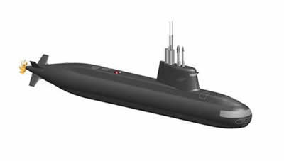
Russia and Italy have decided to optimize their joint next-generation diesel submarine project, a Russian naval design bureau said Friday. The S-1000, a 1,000-ton diesel submarine, is a joint project begun in 2004 by Russian submarine builder Rubin and Italy’s Fincantieri. Russia and Italy presented a mockup model of the S-1000 at an international arms show in France in October 2006. Andrei Baranov, deputy head of the Rubin Central Design Bureau, said that in its proposed configuration, the S-1000 is of “little interest” for potential clients, adding that a decision had been made to improve the project and target specific countries that need a submarine fleet. The submarine was originally designed for anti-submarine and anti-ship warfare, reconnaissance missions, and transportation of up to 12 troops. It is 56.2 meters long, has a top speed of 14 knots and is equipped with a new fuel cell-powered Air Independent Propulsion (AIP) system developed by the Italian firm. Although its exterior will stay as designed, there will be considerable changes to “what’s inside” the submarine, Baranov said, adding that the target regions for selling submarine would remain the Middle East and Southeast Asia. He cited several reasons for the upgrading the sub, including to market it to the Russian and Italian navies. He said the S-1000 design was drawn up almost a decade ago and much has changed since then. And, he noted, such small submarines are currently in great demand in the world, and there is intense competition on the market. “Countries that are actively looking for new submarines are setting some totally unexpected demands for those ships,” he said.
China Manned Submersible Samples Mineral Deposits.
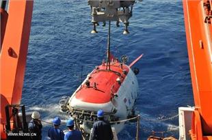
China's manned submersible Jiaolong discovers extensive iron-manganese deposits subsea South China Sea. "The Jiaolong began to dive at 9 a.m. Wednesday and arrived at its scheduled depth about 110 minutes later. We sailed northwest, climbed a forty-meter-high slope and found a large deposit of iron-manganese," said Tang Jialing, pilot of the submersible and a researcher from the National Deep Sea Center. Eight samples were taken from these deposits. "Since one of the samples was broken by the sub's robotic arm, a round core inside could be identified as volcanic lava. The materials covering the core are iron and manganese oxides, which need tens of thousands of years to form," said Zhou Huaiyang, a professor at Tongji University. The Jiaolong will carry out another two dives in the area, as well as conduct research on the Jiaolong Seamount, which was named after the sub after scientists aboard the vessel discovered it. Zhou said he hopes more rock samples will be collected from the seamount during the two dives. During its 113-day mission, the sub will engage in scientific research in the South China Sea, the northeast Pacific Ocean and the west Pacific. The mission marks the start of a five-year trial period for the Jiaolong before it starts regular operation.
James Bond’s Lotus Esprit submarine goes up for auction.
James Bond’s Lotus Esprit submarine, one of the most memorable cars from the 007 movie franchise, is going up for sale in September. The car, which saved Bond – as played by Roger Moore – from a murderous helicopter gunship in 1977′s The Spy Who Loved Me, will go under the hammer on September 8 at RM Auctions in London; it’s actually one of seven different cars created to film the surprise submarine transformation. In the film, Bond – accompanied by KGB agent Major Anya Amasova – drives the Lotus into the sea to escape the helicopter attack, then fires a torpedo to blast it out of the skies. The film crew created or commissioned seven different variations for the sequence, as the wheels fold in, dive-plane pods emerge, and the car transforms into a waterproof (barring bullet holes) craft. This particular car, however, is perhaps the most exciting: the actual submarine Lotus, made by Perry Submarines, which was in effect a fully functional mobile sub dressed up to look like the Esprit. The craft wasn’t waterproof, however, and so was piloted by a diver using battery-powered motors, with a top speed of around ten knots.
Unfortunately there was no provision for actually converting it back into a road-going vehicle, and so the scenes showing the Lotus emerging onto the beach were filmed with yet another car. That was pulled up on hidden tracks, out of the water. RM Auctions hasn’t said what it expects the iconic Esprit to fetch at auction, though it could be considerable. Back in 2010, the same auction house held the sale of the Aston Martin DB5 that featured in Goldfinger, which eventually sold for £2.6m ($4m).
Manned Submersible to Hunt Invasive Florida Lionfish.
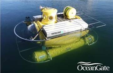
OceanGate, is helping to raise awareness of the widespread invasion of lionfish, a non-native predator known for its venomous spines and increased numbers in the waters of Florida, the Caribbean and the Gulf of Mexico. From June 27 to 29, 2013, the five-person manned submersible Antipodes will take scientists on a series of dives off the Florida coast to study the growing lionfish population. The goal of the three days of diving and panel discussions is to foster long-term collaboration among scientists to halt the unprecedented expansion of this invasive species. Native to the South Pacific and Indian Oceans, lionfish have been increasingly affecting fisheries and tourism since they were introduced to the Atlantic Basin sometime in the early 1990s. Due to fast reproductive rates and lack of any natural predators, lionfish are able to reach a population density of 200 per acre and reduce native fish populations by up to 80 percent. This threat extends from the marine environment to the economy as recreational saltwater fishing on Florida's east coast "generated 29,000 jobs and $3.3 billion in sales" in 2011 alone, according to NOAA. "Our expedition is an opportunity for some of the most respected marine experts in the region to come together and find a way to further science on the lionfish epidemic," states Stockton Rush, OceanGate founder and CEO. "Lionfish are a serious threat to the ecosystems of the Atlantic, Gulf of Mexico and Caribbean waters, and we're pleased to provide our manned submersible for this research initiative and for the collaboration between organizations such as Nova Southeastern University (NSU) and the Florida Fish and Wildlife Conservation Commission, all of which share an interest in raising awareness and exploring methodologies for lionfish population controls." OceanGate first raised national awareness of the lionfish threat in 2012, during the discovery of a downed World War II Hellcat fighter aircraft. Footage of the wreck showed a dramatic number of lionfish and caught the attention of marine biologists. The expedition will be hosted at Nova Southeastern University's Oceanographic Center in Hollywood, Florida, and will conclude at the state-of-the-art facility on Saturday, June 29, with a panel of leading experts on aquatic invasive species. Scientists will discuss the data, their first-hand observations, and imagery captured during the expedition. Following the summit, Chef Kareem Anguin from The Oceanaire Seafood Room in Miami will showcase some of the tastiest ways to cook lionfish to help promote commercial fishing of the species.
South Korea Submarines.
South Korea recently launched the first of a second batch of six Type 214 submarines. This one was built by Daewoo Shipbuilding & Marine Engineering. The first three were built (from German components) by Hyundai Heavy Industries. Much to the chagrin of the South Koreans, who are trying to develop their own submarine building capability, the first three Type 214s had quality problems. Mostly it was defective components and poor construction techniques that left the three boats noisy and easier to detect. The first three Type 214 subs were out of action for most of 2010 because of these problems. This was very embarrassing, as these subs were built in South Korea and that was a big deal in South Korea. Building submarines is a very specialized and exacting type of manufacturing, and South Korea has only been doing it for less than a decade. The first subs built in South Korea were these three German Type 214s, and the first of those entered service![]() five years ago. The boats were built using licensed technology from the German developer (HDW) and many of the components were manufactured in South Korea as well. But then metal bolts in the Type 214s began coming loose or breaking seven years ago. The problem was traced to the South Korean supplier of the bolts which were not, it turned out, manufactured to the German specification. Eventually, German specialists were called in, and by 2011 the problem had been fixed. South Korea went ahead with plans to build six additional Type 214 subs over the next 12 years. South Korea already had nine 1,100 ton Type 209 subs, designed and built in Germany. The Type 214 boats use fuel
five years ago. The boats were built using licensed technology from the German developer (HDW) and many of the components were manufactured in South Korea as well. But then metal bolts in the Type 214s began coming loose or breaking seven years ago. The problem was traced to the South Korean supplier of the bolts which were not, it turned out, manufactured to the German specification. Eventually, German specialists were called in, and by 2011 the problem had been fixed. South Korea went ahead with plans to build six additional Type 214 subs over the next 12 years. South Korea already had nine 1,100 ton Type 209 subs, designed and built in Germany. The Type 214 boats use fuel![]() cells, enabling them to stay underwater for up to two weeks. The Type 214 is a 1,700 ton, 65 meter (202 foot) long boat, with a crew of 27. It has four torpedo tubes and a top submerged speed
cells, enabling them to stay underwater for up to two weeks. The Type 214 is a 1,700 ton, 65 meter (202 foot) long boat, with a crew of 27. It has four torpedo tubes and a top submerged speed![]() of 35 kilometers an hour. Maximum diving depth is over 400 meters (1,220 feet). AIP boats go for up to a billion dollars each. The second batch of South Korean 214s will have an improved AIP system, which is apparently more reliable and provides a small increase in time underwater. South Korea will probably become a supplier of AIP systems as well because they now have the industrial expertise for this sort of high tech. The latest Type 214 boat is important because if it proves to be flawless it will make South Korea a contender in the international submarine market.
of 35 kilometers an hour. Maximum diving depth is over 400 meters (1,220 feet). AIP boats go for up to a billion dollars each. The second batch of South Korean 214s will have an improved AIP system, which is apparently more reliable and provides a small increase in time underwater. South Korea will probably become a supplier of AIP systems as well because they now have the industrial expertise for this sort of high tech. The latest Type 214 boat is important because if it proves to be flawless it will make South Korea a contender in the international submarine market.
Lithium ion batteries for special operations mini-submarines.
![]() U.S. Navy power electronics experts needed lithium-ion batteries for prototype mini-submarines designed to transport combat swimmers such as Navy SEALs covertly while minimizing swim time to maintain combat effectiveness. They found their solution from General Atomics in San Diego.Officials of the Naval Surface Warfare Center in Crane, Ind., have awarded a $12.5 million contract to General Atomics for lithium ion batteries to be used on the Dry Combat Submersible program of U.S. Special Operations Command (SOCOM) at MacDill Air Force Base, Fla.The batteries and accessories will be used on Navy submersible vehicles as primary sources of power, Navy officials say. General Atomics has experience in nuclear and alternative energy, electromagnetic aircraft launch and recovery systems, and unmanned aerial vehicles (UAVs) that rely on battery power.The SOCOM Dry Combat Submersible program involves two separate initiatives -- the Dry Combat Submersible-Light (DCS-L) program and the Dry Combat Submersible (DCS). Both initiatives are developing technology to deliver combat swimmers to their mission areas ready to fight, rather than exhausted by long swims.Submarine experts at the General Dynamics Electric Boat in Groton, Conn., are developing the DCS-L, and those from the Lockheed Martin Corp. Mission Systems and Training segment in Palm Beach, Fla., are developing the DCS.The two sizes of mini-submarines are intended to operate from combat support surface ships or submarines. They are to be one-atmosphere special operations dry combat submersibles that will be free-swimming vehicles capable of delivering and extracting teams of combat swimmers. USSOCOM officials are interested in dry combat submersibles that can move at speeds of at least five knots, at depths to 200 feet, with provisions for two pilots.These dry submersibles should be sized to transport aboard C-5 or C-17 cargo jets, or in standard 40-foot surface ship containers. The submersibles are to have military radios, military sonars, and high power batteries.These submersibles would operate from surface support ships or submarines equipped with pressure-proof shelter systems either military or commercial, or future generations of the Dry Deck Shelter (DDS).The General Dynamics Dry Combat Submersible-Light will be about 24 feet long with moderate endurance and moderate passenger and cargo capability that will be operated from specially configured commercial surface ships.The larger Lockheed Martin version of the Dry Combat Submersible will be about 38 feet long with high endurance and high passenger and cargo capability that will be operated from specially configured commercial surface ships, and potentially from future submarine shelter systems.
U.S. Navy power electronics experts needed lithium-ion batteries for prototype mini-submarines designed to transport combat swimmers such as Navy SEALs covertly while minimizing swim time to maintain combat effectiveness. They found their solution from General Atomics in San Diego.Officials of the Naval Surface Warfare Center in Crane, Ind., have awarded a $12.5 million contract to General Atomics for lithium ion batteries to be used on the Dry Combat Submersible program of U.S. Special Operations Command (SOCOM) at MacDill Air Force Base, Fla.The batteries and accessories will be used on Navy submersible vehicles as primary sources of power, Navy officials say. General Atomics has experience in nuclear and alternative energy, electromagnetic aircraft launch and recovery systems, and unmanned aerial vehicles (UAVs) that rely on battery power.The SOCOM Dry Combat Submersible program involves two separate initiatives -- the Dry Combat Submersible-Light (DCS-L) program and the Dry Combat Submersible (DCS). Both initiatives are developing technology to deliver combat swimmers to their mission areas ready to fight, rather than exhausted by long swims.Submarine experts at the General Dynamics Electric Boat in Groton, Conn., are developing the DCS-L, and those from the Lockheed Martin Corp. Mission Systems and Training segment in Palm Beach, Fla., are developing the DCS.The two sizes of mini-submarines are intended to operate from combat support surface ships or submarines. They are to be one-atmosphere special operations dry combat submersibles that will be free-swimming vehicles capable of delivering and extracting teams of combat swimmers. USSOCOM officials are interested in dry combat submersibles that can move at speeds of at least five knots, at depths to 200 feet, with provisions for two pilots.These dry submersibles should be sized to transport aboard C-5 or C-17 cargo jets, or in standard 40-foot surface ship containers. The submersibles are to have military radios, military sonars, and high power batteries.These submersibles would operate from surface support ships or submarines equipped with pressure-proof shelter systems either military or commercial, or future generations of the Dry Deck Shelter (DDS).The General Dynamics Dry Combat Submersible-Light will be about 24 feet long with moderate endurance and moderate passenger and cargo capability that will be operated from specially configured commercial surface ships.The larger Lockheed Martin version of the Dry Combat Submersible will be about 38 feet long with high endurance and high passenger and cargo capability that will be operated from specially configured commercial surface ships, and potentially from future submarine shelter systems.
Failure of India’s Submarine experiment.
On May 10, 2009, Indian Navy Chief Admiral Sureesh Mehta had stated that New Delhi “will soon float tenders to acquire six submarines.” Mehta also accused Beijing by saying, “Indian Navy would keep a close watch on the movements of Chinese submarines which are operating out of an underground base in the South China Sea” and “wish to enter the Indian Ocean”. However, under the pretension of Chinese threat, Washington, New Delhi and Israel are plotting to block the sea lanes of the Indian Ocean for their joint strategic goals. Apart from Israel, New Delhi also purchased modern weapons from Russia, US and other western countries, especially to develop its naval programme. However, Indian experiment failed when on August 14, this year, its navy submarine INS Sindhurakshak caught fire after a huge explosion, and sank along side its berth. The next day, it went down completely with 18 crew members. At the time of incident, the submarine was fully weaponised with torpedoes and Russian made land attack missiles. INS Sindhurakshak was commissioned in to the Indian Navy on December 24, 2007. It underwent major modifications and upgrades in Russia at a cost of $80 million. Showing contradictory statements, Indian defense analysts and various submarine officers have delved on the possibilities which caused fire and loud explosions on board the submarine. Many of them opined that two of the on board missiles accidentally got fired—the detonation of missiles, one of which struck the wall, the second partially damaging another submarine berth along side, is the main cause of the incident. While some others pointed out that anti-Submarine Warfare officer, while running down the tests on the missiles, might have accidentally triggered the missiles or might have been lacking expertise in operating Fire Control System. It was also possible that night time loading of the missiles might have tired the sailors out and the missiles were wrongly housed. While addressing Parliament, the Indian defense minister, confirmed to the house that blasts on the submarine might have been caused by possible ignition of armament. This theory is also seconded by the Russian manufacturers of the submarine. They also point to human error as a crew member, while wrongly checking the connectivity of the missiles might have led to short circuiting, leading to explosion of the hydrogen fumes and triggering of the missiles. In fact, the night time loading of the missiles is carried out for secrecy when a submarine is scheduled to proceed on war patrol. According to Indian media, the night before the accident, the submarine was ready in all respects to proceed to sea in first light on August 14. Also, many of the defense analysts and media persons have even gone to relate the night time arming of the submarine to building of tensions along the Line of Control (LoC) between India and Pakistan. The fact that the two significant evolutions were compromised at one time in complete violation of Standard Operating Procedures (SOPs), has also been referred to by the same analysts as expediting the preparations—the lower threshold of Indian navy’s forward posturing. The nuclear analysts are also perplexed that such compromises being carried out by officer cadre of Indian Navy, what would have happened, if it was not a conventional submarine but a nuclear submarine. The experts stopped short of narrating dire consequences, if such incident happened on Indian nuclear submarine berthed along side in one of India’s harbors. Russians are uncomfortable with India’s ability to safely in running nuclear submarine, and therefore, they have kept a team of around ten Russian nuclear submarines’ technicians on board on its ‘Akula’ Class submarine leased to India. It is not new incident, since 2005, at least 10 serious incidents have been reported. Among them five are related to the Sindhughosh-class of submarines, of which Sindhurakshak is the one. For example, in April 2006 INS Prahar Naval Patrol vessel was sunk. Similarly, in January 2008, INS Sindhu-gosh, with a large foreign-owned cargo ship meant a cold watery grave. And in January 2011, Indian naval ship INS Vindhyagiri caught fire after collision with a foreign merchant vessel at the Mumbai harbour. Nevertheless, whatever the dynamics which led to the sinking of Indian submarine Sindhurakshak, the failure of experiment highlights the professional incompetence, violations of SOPs, poor standards of safety conscientiousness. The incident has certainly brought down the Indian navy’s submarine capability. The ill-preparedness of Indian navy in handling such crises has also been highlighted. Due to its inability to deal with such accidents, India has approached US and Scandinavian experts who have carried out their surveys and now await heavy machinery and heavy cranes to lift the submarine out of water.
Dual Use Submersible Vehicle Wins Prestigious R&D 100 Award.
Proteus, a new class of underwater vehicle that is unique in its ability to operate in either manned or autonomous mode, has been recognized as one of the best technical products of the year. With large payload capacity, long range, high endurance, and advanced autonomous behaviors, Proteus provides capabilities unavailable in other unmanned underwater vehicles (UUVs). Combined with its long range and large cargo capacity, this dual capability provides a highly flexible undersea vehicle that can transport divers or deliver payloads at distances of hundreds of miles without human intervention. Based on the heritage of the Swimmer Delivery Vehicle (SDV) built by The Columbia Group and proven in operation with Special Operations Forces Teams, Proteus incorporates cutting edge autonomy software and high-energy-density batteries by Bluefin Robotics to dramatically expand the capabilities available to users of underwater vehicles. The vehicle can be used for a variety of tasks including: payload integration, test and comparison; advanced autonomy development; long range and stand-off experiments; transporting and installing equipment on the sea floor; inspecting undersea infrastructure such as bridge pilings, undersea pipelines and oil rigs; and transporting divers and cargo. Compared to conventionally-sized UUVs, Proteus markedly reduces the need for frequent launch and recovery for any of these applications and can carry much larger payloads or cover much greater distances than has previously been possible. In applications such as undersea inspection that now depend on remotely-operated vehicles (ROVs), Proteus can reduce the need for costly surface support ships because it can operate autonomously.
Vietnam's third black-hole sub coming soon.
Russia's Admiralty Shipyard in St. Petersburg said it will float out the third of six Project 636 Varshavyanka-class submarines being built for Vietnam's navy by the end of the month, RIA Novosti reported. The Varshavyanka class, with more advanced stealth technology and an extended combat range, is an improvement on its predecessor, the Kilo class of submarines, RIA Novosti said. The U.S. Navy calls the diesel-electric subs black-holes because their technology makes them nearly undetectable when submerged. Vietnam will use the 3,100-ton submarines primarily for anti-shipping and anti-submarine missions in relatively shallow waters. RIA Novosti said Vietnam ordered the six submarines in 2009 to counter China's increasing naval influence in the region. The contract, worth around $2 billion, includes training of Vietnamese crews in Russia. A Vietnamese crew has been training since April in the first of the submarines, the Novorossiisk, that completed its 100-day sea trials last month and is expected to be delivered in November, Admiralty Shipyards said. Admiralty will float out Vietnam's fourth Varshavyanka-class vessel in November, with delivery of the last vessel to Vietnam scheduled for 2016. A report by Naval-Technology in August last year said the Varshavyanka-class vessels have a range of 400 miles using electronic propulsion and can patrol for 45 days. The submarines carry a crew of 52 and feature 533mm torpedo tubes and Kalibr 3M54 (NATO SS-N-27 Sizzler) cruise missiles, developed by Russia's Novator Design Bureau. Top speed is 20 knots and diving depth is about 985 feet. The shipyard also said the first of another six being built for Russia's Black Sea Fleet would be floated out in November.
Submersible Cyclops: Hull Design "Revolutionary"
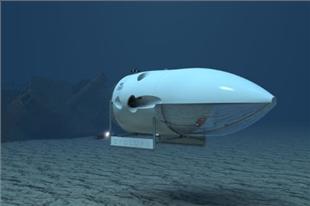
OceanGate Inc. announced the completion of the initial carbon fiber hull design and feasibility study for its next generation manned submersible – Cyclops. Under a contract issued to Boeing Research & Technology (BR&T), OceanGate, the Applied Physics Laboratory at the University of Washington (APL-UW) and Boeing have validated the basic hull design for a submersible vehicle able to reach depths of 3,000 meters. With its large 180-degree borosilicate glass dome, the new vehicle will offer clients a chance to examine the environment, collect samples, and deploy technology in subsea settings in person and in real time. When commercially available in 2016, Cyclops will be the only privately owned deep-water (greater than 2,000 meters) manned submersible available for contracts. A follow on 6,000-meter version is slated for completion in Q4 2016. "Recent advances in material science, manufacturing and testing facilities that combine innovative engineering processes have allowed for a unique collaboration between OceanGate, Boeing and the APL team to complete the feasibility study and move the process to the manufacturing stage," states Stockton Rush, CEO. "The research, military and commercial markets need more vehicles for subsea exploration. OceanGate's Cyclops submersible will usher in a new class of vehicle to help fulfill this need." The Cyclops submersible will feature a seven-inch thick, individual-fiber-placed carbon fiber hull using proprietary Boeing manufacturing technology. The ability to accurately place thousands of individual strips of pre-impregnated fiber will overcome many of the hard to control variables surrounding traditional filament winding processes and permit the hull to withstand the very high compressive loads at 3,000 meters (300 bar). The use of carbon fiber will also help make Cyclops significantly lighter than other subsea manned submersibles, making deployment operations faster, easier and cost-efficient. While in the water, Cyclops' five crew members can comfortably observe the ocean depths through a massive glass dome, which offers unobstructed views for at-depth inspections, environmental assessments, discussion, decision making and observation. Operating at depths beyond 1,000 meters with remotely operated vehicles is extremely difficult as they require large heavy tethers and specialized support vessels. Cyclops will eliminate the tethering limitations and allow its five crew members to observe underwater environments for up to eight continuous hours. Using a patent-pending submerging Launch, Retrieval and Transport (LRT) platform, OceanGate can operate a manned vehicle with ships of opportunity at much lower costs than most other manned vehicles and, in many cases, even less expensively than ROVs. With the ability to be quickly and affordably deployed around the world, Cyclops will usher in a new generation of oceanic exploration and study.
Russia, China: Strategic partners or rivals, and the India factor.
The Russia-China relationship is perhaps one of the most intriguing relationships of contemporary times. Are they ‘comprehensive strategic partners’, as they proclaim? The answer is ‘yes’ and ‘no’. Are they rivals? The answer is again the same: ‘yes’ and ‘no’, depending upon which particular sectors of the globe you are looking at and what areas of activity you have in mind. And when it comes to India – in the framework of South Asia or Indo-Pacific, or Southeast Asia or Central Asia – the Russo-Chinese equation gets all the more muddled and befuddled! Here is an attempted explanation, though the caveat from this writer is that such an explanation is bound to be in the mode of volatile changeability, depending on the fast-evolving global strategic environment. To take the last point first, the Sino-Indian-Russian strategic triangle is a study in real-politik. Submarines are an important area. No, we are not talking here about the sinking of INS Sindhurakshak on the midnight of August 14 in Mumbai naval dockyard as it is an entirely different story. Construction of submarines is one area where the three powers – India, China and Russia – find themselves in cross-currents of geo-politics. Here is how. China has been developing submarines at a pace which indicates the need for sudden enhancement in its submarine capability. With increasing focus on disputes in the South China sea and other regions, China has realised the need for consistency in building its underwater operational capabilities. In this connection, China has commenced construction of new Yuan class submarines at Jiangnan Shipyard in Shanghai. Submarines of this class are already being manufactured at Wuchang Shipyard. Inputs also suggest that Jiangnan Shipyard under China State Shipbuilding Corporation (CSSC) has been assigned to build two-Yuan Class submarines. A recent sighting and imagery report of a Yuan Class submarine at the Jiangnan Shipyard confirms the same. This indicates that submarine construction expertise is growing outside of the purview of China Shipbuilding Industry Corporation (CSIC). However, there are no indications so far that CSSC is involved in ‘submarine design work’, which suggests that these ‘companies and their design institutes’ share submarine design and construction information. China is also seeking assistance from Russia in this regard. The Russian shipbuilding industry got a deal from China in March 2013 to sell four submarines to China – two of which will be built in Russia and two in China. This is the first time in a decade that Russia has obtained a big-ticket defence purchase order from China, though neither side has officially quantified it in terms of monetary value. The next generation advanced conventional submarine (ANGSS) jointly developed by Russia and China will be significantly different from the Russian LADA class. The Russian industry will install a number of Chinese technologies and sub-system on the foundation of LADA/AMUR submarine, including the AIP technology, and develop probably a brand new class of Chinese edition of next generation conventional submarine. Russian LADA class is equipped with AIP technology based on ‘fuel cells technology’, whereas currently the Chinese AIP submarines are based on ‘Sterling engines technology’. Some inputs indicate that since many of the sub-systems, including the cutting-edge Sonar, EW and data-link technology of the LADA class are highly classified, it will not be exported to China. Therefore, Russian shipbuilding industry feels that even if the official contract is signed, it will be implemented in several phases. Russians have not yet discussed plans and technical details of joint development of next generation advance submarines with China and the discussions are still at a very initial stage. Now coming back to the first two questions raised at the beginning of this article – whether Russia and China are strategic partners or rivals – here is an attempt to piece together the zigsaw puzzle of the Sino-Russian relationship. Earlier this month, Russia conducted its biggest military maneuvers since the Soviet times in its far eastern region, involving 160,000 troops, 5000 tanks and 130 fighter aircraft. The drills on Sakhalin Island in the Pacific were watched by Russian President Vladimir Putin. Russia had notified all its neighbours about the exercises and had elaborately explained the motive behind these exercises to China. Yet, an unmistakable message was sent to China and many experts saw these exercises as a subtle warning to China. The Russian message to China, implicit in these exercises, was: do not harbor expansionist plans. Probably this was the best way for Russia to tell China that a rising China should not take Russia for granted! Moreover, the way geo-politics is panning out in Southeast Asia and Central Asia, Russia and China are not on the same page. At a time when China has been upping its ante in Southeast Asia for the last five years or so and is involved in maritime boundary disputes in the South China Sea, Russia has maintained a stony silence on the subject. To rub it further on China, Russia has even signed commercial deals with Vietnamese companies for joint exploration and exploitation of oil and gas in those very South China Sea waters that are being claimed by China. In Central Asia also the Russians are wary of the increasingly marauding Chinese influence in the region which the Russians regard as their backyard. Uzbekistan is the only among the five Central Asian nations whose trade with Russia is more than with China. The Russians are also not unmindful of the vast oil-gas pipeline network that the Chinese have already set up in Central Asia. The unfolding enigmatic Sino-Russian relationship should be the most exciting to watch. And one should not forget in this context the ‘I’ in the BRICS set up – India.
Manned submersible circles globe to pursue mysteries of deep-sea life.
The water darkens and becomes pitch black as three men in a cramped submersible descend near the British Cayman Islands in the Caribbean Sea. Then the real stars of the show appear: Creatures thriving in an environment long thought difficult to sustain life. About 340,000 people watched the world’s first live broadcast of the deep-sea expedition on the “Nico Nico Live” online channel on June 22. The spectacle from a depth deeper than the 3,776-meter Mount Fuji and where sunlight cannot reach was made possible by the Shinkai 6500, a manned research submersible of the Japan Agency for Marine-Earth Science and Technology (JAMSTEC). The Shinkai 6500 is currently circling the globe for a string of scientific expeditions that have been joined by scientists from the United States, Britain and other countries. The voyage is driven not by national ambitions for natural resources, but by an intellectual curiosity to uncover mysteries in vast areas of the planet that have never been explored. The findings in these extreme environments, such as hydrothermal vents and the crushing pressure in ultra-deep seas, could provide clues on the origins of life itself on Earth. The Shinkai 6500 can travel as deep as 6,500 meters. In the dive near the Cayman Islands, the vessel sank at a rate of 40 meters per minute. The submersible can accommodate a crew of only three, comprising one scientist and two pilots. When the screen was switched to show the image from an inboard camera, viewers saw how Ken Takai, director of the JAMSTEC Extremobiosphere Research Program, shared a cabin--an orb of titanium alloy only 2 meters across--with his two colleagues. Sea water temperatures are a chilly 1 or 2 degrees more than 2,000 meters beneath the surface. Curled up in winter suits, the crew members ate lunchboxes before they hit the 5,000-meter-deep seabed at the end of the two-hour descent. Lights on the submersible revealed hot water spewing from “chimneys,” or column-shaped seabed formations several meters high. Takai and his colleagues operated two robot arms to catch the small shrimp and sea anemones that crowded the chimneys, and placed them into a sampler. The robot arms also installed a thermometer beside a hydrothermal vent. Camera imagery of the deep sea was transmitted through purpose-built fiber-optic cables to the seaborne support vessel Yokosuka, and then relayed via satellite for “Nico Nico Live” viewers. A 10-year international research project that started in 2000 revealed many facts about the distribution and diversity of marine life. But Hiroshi Kitazato, research director of the JAMSTEC Institute of Biogeosciences and leader of the current global journey, said much remains to be learned. “Most of the seas more than 2,500 meters deep or in the Southern Hemisphere have yet to be surveyed,” Kitazato said. “To fill those gaps, we are focusing on four marine areas, most of them depths in the Southern Hemisphere, during the current journey.” The Shinkai 6500 left its home port in Yokosuka, Kanagawa Prefecture, on Jan. 5 on board the Yokosuka support vessel. It surveyed Indian Ocean waters off Madagascar between late January and March, the same location where a group of U.S. scientists in 2001 discovered the scaly-foot gastropod, a snail species whose crust and scales are coated with black iron sulfide. During an expedition in the same area in 2009, the Shinkai 6500 caught white variants of the scaly-foot gastropod that were not coated with iron sulfide. Scientists still cannot explain what caused the difference within the genetically identical species. The white variants also had tougher scales, raising the question about the role of iron sulfide. Both white and black specimens were caught during the latest expedition and are being raised aboard the Yokosuka. The scientists plan to investigate the formation process and the role of the coating. The hot water spouting from the seabed in the area contains high concentrations of hydrogen. The scientists hope to study organisms living near the hydrothermal vents to gain insight into the evolution processes of early life. Incipient life on primordial Earth is believed to have relied on hydrogen for its energy. The Madagascar expedition was followed by dives in the Atlantic Ocean off Brazil in April and May. It was the first full-scale scientific expedition in that area, home to sea mounts towering more than 5,000 meters in height and currents flowing in from both the Antarctic and North Atlantic oceans. The scientists confirmed that deep-sea corals, benthos and other creatures inhabited that complex environment. They hope to investigate how habitats vary with depth and geology. Seabed geology was also a study subject on its own. Scientists held a news conference in Brazil to announce the discovery of granite, a likely remnant of a continent. Media organizations around the world likened the story to a discovery of Atlantis. While legend says the Atlantis continent sank 12,000 years ago, the granite is estimated to have submerged in the ocean several tens of millions of years ago. The finding nonetheless provided an occasion for touting the romantic side of the scientific journey. The online relay took place at the third stop, on the voyage in the Caribbean Sea, where the temperature of the hot water spouts is estimated at 500 degrees. The scientists caught sea anemones, small shrimp and other creatures to study micro-organisms inhabiting the hydrothermal field, with which they live in symbiosis. Marine creatures used to travel back and forth past this area when the Pacific and Atlantic oceans were connected. But that traffic was blocked when the North and South American continents became connected 3 million years ago. The scientists plan to study how creatures of Pacific origin evolved in the Atlantic to gain insight into the acclimatization and evolution processes of living organisms. The Shinkai 6500 returned to Japan on Aug. 2 for recharging operations ahead of another expedition, from October, in the Tonga Trench, the second-deepest area in the world. “In only 2 percent of all marine areas do depths exceed 6,500 meters,” said Toshio Tsuchiya, a senior official in the JAMSTEC Marine Technology and Engineering Center. “That means the Shinkai 6500 can cover most areas.”
Kilo Class submarines.
As news came in that all 18 sailers aboard the Indian Navy's Kilo Class submarine INS Sindhurakshak may be died after a massive explosion rocked the vessel, here is a look at what a Kilo Class submarine is. The Kilo Class is the NATO designation for a naval diesel-electric submarine made in Russia. The original version of the vessels were designated Project 877 Paltus (Halibut) in Russia. The Kilo Class submarines are mainly intended for anti-shipping and anti-submarine operations in relatively shallow waters. Original Project 877 vessels are equipped with Rubikon MGK-400 sonar system, which includes a mine detection and avoidance sonar MG-519 Arfa. The first Kilo Class submarine entered service in the Soviet Navy in 1980, and the vessel continues to be in service in Russain Navy. A total of 14 such vessels are believed to be in Russian Navy's fleet, with 17 in active service and seven in reserve. Till today, 33 such vessels have been exported to India, Algeria, China, Poland, Iran and Vietnam. Also, Venezuela and Indonesia have showed interest in acquiring Kilo Class submarines. These submarines are 70-74 metres long. The submarine can travel at the maximum speed of 10-12 knots when surfaced and 17-25 knots when under water. The submarines are propelled by a diesel-electric engine which generates 4,400 kw of power. These submarines can travel up to 700 km at 6 km/h when submerged. It can snorkel up to 11,000 km at 13 km/h. The vessels can stay in the sea for 45 days at a stretch, after which they need to return to docks/nearest port. These vessels can carry up to eight surface-to-air missiles and can carry 18 torpedoes or 14 underwater mines. These can carry 52 personnel on board. The price of one Kilo-Class vessel ranges between $200-250 million.
Indian submariners die after being trapped by explosion, fire.
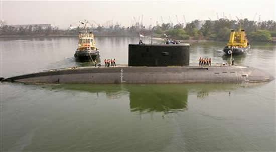
Divers were desperately trying to pry open the hatches of an Indian submarine in which several sailors died or were trapped after an explosion and fire on Wednesday in the navy's worst loss since the 1971 war with Pakistan. Eighteen sailors were aboard the Russian-built INS Sindhurakshak when the blast struck after midnight. The accident soured a week of naval milestones, including the launch of a locally built aircraft carrier aimed at giving the navy heft as it competes with China in the Indian Ocean. Defence Minister A.K. Antony said crew members inside the diesel-electric Kilo-class submarine berthed at the main base in Mumbai had died. But he gave no details, more than 12 hours after the incident, which revived memories of explosions on the Russian nuclear-attack submarine Kursk in the Barents Sea in 2000. Its entire crew of 118 died. "There was an explosion immediately after midnight in the forward side of the submarine, where missiles and torpedoes are kept to be used whenever necessary," a naval source said. "Now the submarine is tilted on the front side and all hatches are closed. They are trying to open those now." He said one or two men are usually on duty on top of the submarine and they either jumped into the water or were thrown off by the force of the explosion. The number of crew in the boat when fully operational is 110. Navy spokesman P.V.S. Satish earlier said efforts were under way to rescue trapped crew members. "We will not give up until we get to them," he said. Photographs distributed by social media users appeared to show a large fireball over the navy dock.The INS Sindhurakshak, which returned from an upgrade in Russia earlier this year, had suffered a similar accident in 2010 in which one sailor was killed while it was docked in the southern port of Visakhapatnam. Typically, such a submarine is fitted with torpedoes and missiles. Torpedoes are launched underwater to attack other submarines while missiles are used for long ranges above water. There was no immediate word on the status of the weapons on board the Sindhurakshak. "Lot of things are in very close proximity, there is fuel, there is hydrogen, there is oxygen, there are weapons with high explosives on board," said retired Indian navy chief Arun Prakash. "So a slightest mistake or slightest accident can trigger off a huge accident. The question of sabotage - I mean, all possibilities have to be considered - but sabotage is probably the last possibility." Another submarine in the Mumbai dock where these vessels are usually tied to each other suffered minor damage, the naval source said. The last big loss for the navy was the sinking of the INS Khukri by a Pakistani navy torpedo during the 1971 war.Most of the country's fleet of 15 submarines is in urgent need of modernisation and has been hampered by delays in government decisions as it battles corruption allegations. Efforts to build a domestic arms industry to supply the military have made slow progress, with the country still the world's largest importer. Earlier this week, a aircraft carrier slipped into the sea, though it is due to be fully operational only by 2017. The navy also announced that the reactor on its first indigenous nuclear submarine was now operational as part of the plan to build a powerful navy to counter China's growing presence in the Indian Ocean. INS Sindhurakshak completed a 2-1/2 year upgrade at a Russian shipyard a few months ago. "This is a very, very old boat that really doesn't go out on long sea patrols," said Bharat Karnad, a senior fellow of national security studies, at the Centre for Policy Research. Three people near the submarine at the time of the explosion were injured and being treated in hospital, navy spokesman Satish said. The blast that ripped through the submarine INS Sindhurakshak has taken the sting out of the Navy’s already-enfeebled submarine arm. On record, the Indian Navy operates10 kilo-class (877 EKM a.k.a Sindhughosh-class) and four HDW (Shishumar-class) submarines besides the nuclear-powered INS Chakra, acquired last year from Russia on a 10 year lease. The regrettable state of the stealthy submarine arm — vital for maintaining the critical sea denial capability — is evident from the fact that the Navy hasn’t been able to shore up its sub-sea patrol capabilities by inducting a new conventional submarine after the year 2000, when INS Sindhushastra, the last of the Kilo-class boats from Russia, was added to the naval inventory. Worse, none of the Indian subs are equipped with air independent propulsion (AIP), which considerably enhances the underwater endurance of conventional diesel-electric submarines. Bereft of AIP, subs are forced to surface once in a few days for recharging their batteries, when they are most susceptible to detection by maritime patrol aircraft on the prowl. While Pakistan took delivery of PNS Hamza fitted with AIP from the French, it has already begun retrofitting two subs of the same class with the system. The Indian experiment of building subs indigenously at Mazagon Dock, which delivered INS Shalki and INS Shankul built on ToT in the early 1990s, went awry when the programme was shelved following allegations of corruption, which resulted in the nation’sloss of capability and skill sets acquired. More or less the same fate awaited the programme kick-started in mid-2000 — as part of the Navy’s high-value 30-year submarine building programme — to build six French-origin Scorpene class submarines at Mazagon Dock. Marred by a string of delays and cost overruns, the first in the class would at best be only delivered in 2016. Among the kilo-class submarines, while most of them have undergone extensive and costly upgrade in Russia, INS Sindhukirti has been idling at the Hindustan Shipyard since 2006. It was an experiment gone wrong that put paid to the submarine. While a section of top officials argued for sending it to Russia for refit, another wanted submarine refit capability to be developed indigenously. Finally, the Navy asked the dying Hindustan Shipyard to upgrade it, retrofitting it with new sensors like Ushus and weapons like the Klub missile. It was an attempt at rejuvenating a yard at the cost of a potent war-fighting platform, lamented a Navy officer. Meanwhile, the nuclear submarine programme to induct nuclear-powered ballistic submarines was announced as maturing at the close of the last decade. INS Arihant, the first of the nuclear subs, was launched in 2009 and its reactor went critical hardly a week ago. hree more vessels of the class are in the offing and Arihant with limited capabilities will be ready for commissioning next year. In the meantime, India has been toying with the idea of a second line of conventional submarines under the Navy’s Project 75-I, which hasn’t borne fruit yet. Last heard, a purchase notice for this is only likely to be issued in the next two months. Desperate to salvage its dipping submarine force-levels, the Navy is learnt to have asked the Defence Ministry to procure two conventional submarines under the project from the foreign collaborator, while four would be built between Mazagon Dock and Hindustan Shipyard.
Navy launches 4th 1,800-ton attack submarine.
South Korea's Navy launched its fourth 1,800-ton Type 214 submarine in a ceremony here on Tuesday as part of efforts to boost its underwater warfare capabilities against North Korean submarines. The ship, named after Korea's famous independence fighter Kim Jwa-jin (1889-1930), is the fourth of its kind in operation since 2010. Kim is Korea's first general of independence fighters who led the Cheongsan-ri battle to defeat 3,300 Japanese soldiers in China's northeastern region in 1920. President Park Geun-hye, Defense Minister Kim Kwan-jin and senior military officials attended the ribbon-cutting ceremony held at Daewoo Shipbuilding & Marine Engineering's shipyard in Geoje Island, close to the southern port city of Busan. The late general's daughter Kim Eul-dong, an incumbent lawmaker of the ruling Saenuri Party, and actor Song Il-kook, his grandson, also attended the ceremony.The ship can hit 300 targets simultaneously, and is equipped with ship-to-land missiles and torpedoes as well as an advanced sonar system for anti-submarine warfare, surveillance and reconnaissance missions. The diesel-powered submarine is operated by Air Independent Propulsion (AIP), which extends the ship's submerged endurance compared to conventional submarines. The AIP system enables the crew to carry out underwater missions for several weeks without the need to access atmospheric oxygen. The Navy will take delivery of the attack submarine in late 2014 and deploy it in 2015 for naval operations, officials said. South Korea currently operates over 10 submarines, including 1,200-ton Type 209 subs and 1,800-ton Type 214 subs. The Navy plans to acquire nine 3,000-ton level heavy-attack submarines after 2020 with significant improvements in their radar and armament systems compared to their predecessors. North Korea is known to have about 70 submarines, one of which is suspected of having torpedoed a South Korean corvette in the tensely guarded western sea in March 2010. A total of 46 sailors were killed in the incident.
The Compact Semi Submarine.

Submarines are not the most common way to cruise the sea. There are actually quite a few ways to enjoy the seas and many of them combine the submarine design. The semi submarine is a small design that resembles a buoy. The buoy-like aquatic vehicle has a deck above the water for chillin’ and an area below the water with a glass window for viewing marine life. Scuba diving and exploring life under the water is always cool. Not everyone wants to suit up and dive. This vehicle is a simple ways to enjoy the seas without the drama of a scuba dive. The four core technology features allow the boat to not move into shallow areas and get stuck. There is also an underwater camera that can monitor the activity above water and keep tabs on the directions that the semi submarine is travelling. The two floating hulls on both sides ensure extreme stability. The Ego is controlled by a wireless controller. Having one of these on deck is essential to make the most of that beach life.
Russia to Float Out 2 New ‘Black Hole’ Submarines
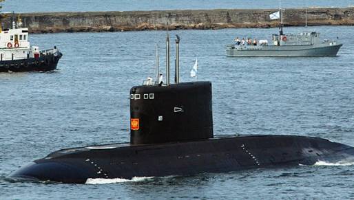
The third of six new “black hole” submarines that Russia is making for the Vietnamese navy will be floated out later this month, the shipbuilder said Monday, adding that the first of another six, for Russia’s own Black Sea Fleet, would be floated out in November.The Varshavyanka-class (Project 636M) diesel-electric subs, dubbed by the US Navy as “black holes in the ocean” because they are nearly undetectable when submerged, are primarily designed for anti-shipping and anti-submarine missions in relatively shallow waters.The first of the submarines, which completed its 100-day sea trials last month and for which a Vietnamese crew has been training since April, is expected to be delivered to that country in November, according to the manufacturer, Admiralty Shipyards. Vietnam ordered the six submarines in 2009, counterbalancing China’s expanding maritime influence in the region. That contract, which also stipulated the training of Vietnamese crews in Russia, was reportedly worth $2 billion. The Varshavyanka class is an improvement on the Kilo, with more advanced stealth technology and an extended combat range. Construction of the first Varshavyanka-class sub for the Black Sea Fleet, a vessel named the Novorossiisk, began in 2010 and has been completed ahead of schedule, the shipbuilder said. The submarines, which feature 533-milimeter torpedo tubes and are armed with torpedoes, mines and Kalibr 3M54 (NATO SS-N-27 Sizzler) cruise missiles, displace 3,100 tons, reach speeds of 20 knots, can dive to 300 meters and carry crews of 52 people.
Triton Submarines to Reveal New Models in Monaco.
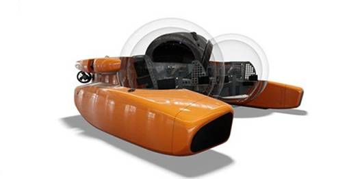
The next generation of Tritons will include 4, 6 and 8 passenger models as well as a 2-passenger model rated for 5500 feet (1,675 meters) and the Triton 36000/3 Full Ocean Depth (rated for 36,000 feet/11,000 meters).In 2011, Triton launched the first Triton 3300/3, which has played a key role in filming marine life for the science community, including the first ever filming of the elusive giant squid at depths of 600-900 metres. Triton’s President, Patrick Lahey, said: “Triton broke new ground with the Triton 3300/3. The 3300/3’s acrylic sphere is the largest and thickest ever produced for a submersible.“Triton’s newest models will once again set the standard for performance and innovation. We are looking forward to introducing our 4, 6 and 8-passenger deep submersibles at the 2013 Monaco Yacht Show.”Triton will also be featuring innovative submersible support vessel (SSV) designs developed in partnership with Bury Design, including the unique Triton Launch and Recovery Catamaran (LARC), a highly efficient SSV capable of speeds up to 20 knots with a range of up to 1,000 nautical miles.
China's craze for DIY plumbs new depths.

It started well for amateur submariner Tao Xiangli , as his home-made underwater craft slid below the surface of an idyllic rural lake, watched by an entire village.But then the submarine stalled and got stuck in the mud. After nearly 10 minutes of anxious waiting, onlookers began to panic. Some dived into the water to check that the submariner was alright. Finally, villagers pulled the vessel and its intrepid inventor to safety.The little adventure of the DIY peasant inventor has become a hit video clip widely circulated on the internet in recent days.Tao, a 34-year-old Beijing-based migrant worker from Anhui province, has become an internet sensation since word began to spread last summer of his unusual hobby - building submarines. His latest craft is six metres long, weighs almost two tonnes, and is made mostly out of metal barrels. The vessel is cramped, with room for only one person.However, it houses all the necessary features of a submarine, such as pressure gauges, monitoring cameras, a TV set, an oxygen supply and headlights. The video of Tao has been popular on mainland portal Sina.com in recent days.The mainland is experiencing a DIY engineering fad, with enthusiasts building everything from submarines and aircraft to robots. Many use countryside ponds and hills to practise, though a lack of safety measures means this type of hobby is not for the faint-hearted.
Yasen-class nuclear attack submarines to give Russia major edge.
Large-scale construction of the next-generation Project 885 Yasen-class multi-purpose nuclear attack submarine, armed with Onyx supersonic cruise missiles has begun in Russia. The ships will compete with the latest American Seawolf-class nuclear submarines in terms of their noise profile and will be world leaders in terms of fire power. Moscow plans to acquire at least 10 of these boats by 2020. The fourth submarine in this class was laid down in Severodvinsk on the eve of Navy Day, which was celebrated on the last Sunday in July. The Project 885 nuclear submarine is the quintessence of everything the Russian military industrial complex has achieved in over half a century of building submarines. The vessel has a hull made from high-resilience low-magnetic steel, and so can dive to a depth of more than 600 metres (conventional boats cannot go deeper than 300 metres), which effectively puts it out of reach of all types of modern anti-submarine weapons. Its maximum speed is more than 30 knots (about 60 kilometres per hour). The nuclear submarine is equipped with an escape pod for the whole crew.The Russian designers say that the Yasen is not only quieter than the Project 971 Akula, but also quieter than the latest American Seawolf nuclear submarine. Moreover, unlike those vessels, the new missile submarine will be more functional thanks to the weapons at its disposal (several types of cruise missile and torpedo) and will be able to fulfil a wide range of roles at sea. The Akula nuclear submarine is currently the most important of the Russian multi-purpose attack submarines designed for raiding operations against sea lanes. Virtually inaudible in the depths of the ocean, they are equally effective against transport vessels and warships, and can also hit the enemy’s coastal infrastructure with cruise missiles. Akula submarines were recently spotted within the 200-mile zone of the coasts of the United States and Canada, which caused a serious commotion among the countries’ respective militaries. Having discovered the presence of these ‘guests,’ neither of them was able to track their movement, which naturally caused serious concern. After all, the Akula carries on board 28 Kh-55 Granat cruise missiles, the equivalent of the American Tomahawk, which can fly 3000 km and deliver 200-kilotonne nuclear warheads to their targets. The main attack system on the Yasen is the P-800 Onyx, the latest Russian supersonic cruise missile. This missile is the base version for two absolutely identical export versions in terms of their appearance: the Russian Yakhont and the Indian BrahMos, although with significantly reduced combat characteristics. These devices are capable of being fired from under water. They fly at a speed of 750 metres per second and carry a devastating high-explosive warhead weighing half a tonne. They have a range of more than 600 kilometres. The Onyx is guided to its target by a navigational system that operates on target designation data, that is inputted provisionally to the missile before it is launched. At a predetermined point in the trajectory (25–80 kilometres), the missile’s homing device is briefly activated and determines the precise location of the target. The homing device is activated again after a sharp reduction in altitude of 5–15 metres, just seconds before it hits the enemy. This is to ensure that when the enemy detects the missile’s launch it cannot ‘jam’ the missile with electronic countermeasures. But it’s not its high speed or the protection of its homing device against electronic countermeasures that makes the Onyx a super-modern weapon. Once it is launched from the submarine, the missile finds the target by itself. After determining their coordinates, the missiles ‘wait’ until the last one is out of the launch tubes and then line up, just like a wolf pack, and begin to ‘home in on their prey’. The designers are not really advertising this point, but it’s the missiles themselves that decide which missile attacks which target and how. The missile ‘pack’ decides these targets, classifies them in terms of importance, and selects the tactics for the attack and the plan for its execution. In order to prevent mistakes, the missile’s on-board computer system is programmed with electronic data on all modern classes of ship. This is purely tactical information – for example, on the class of vessel. This enables the missiles to determine what they are up against, whether it be an aircraft-carrier or landing group, and then to attack the main targets within the group. The Onyx missile’s on-board computer also holds data on how to counter the enemy’s electronic warfare systems, which can divert a missile from its target, and systems for evading anti-aircraft defence systems. At the same time, like wolves in a real pack, the missiles themselves decide which one of them is the main attacker and which one must take the role of the decoy to lure the enemy’s aircraft and air defence systems away. Once the main selected target has been destroyed, the other missiles immediately redistribute the combat assignments between themselves and begin to destroy other vessels. There is no ship in the world that can dodge an attack by Onyx missiles. Yes, ship-borne radar systems can detect that they have been launched, but then further resistance is useless. The speed of these missiles and the way they constantly manoeuvre above the surface of the sea makes it practically impossible to intercept them with air defence systems or aircraft. Another advantage of the Onyx missile is that it can be used with various types of carriers. In Russia, it is installed not only in submarines but also on surface vessels and mobile land-based platforms – the Bastion shore-based missile systems. It’s the presence of these systems in Syria that so worries Washington today. Onyx will also be included in the weaponry of the Su-30MK family of fighters and the latest Su-34 frontline bombers. But the most important thing is that the next generation following the Onyx is already on its way. This is the Zircon, the first hypersonic combat missile system, for which testing is due to start next year.
SA Navy crippled by lack of qualified personnel.
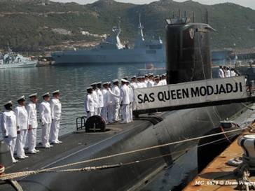
According to a well-placed source in the South African defence environment, only one of the three submarines can go to sea as the South African Navy (SAN) only has enough personnel to man one at a time. Further compounding this is the fact that the Navy’s submarine fleet spends two thirds of its time in the dockyard. The submarine SAS Manthatisi is still in the dock as she undergoes maintenance related to electrical systems – the batteries were damaged in 2007 when a sailor plugged in an incorrect electrical system. According to the source, the entire electronics of the submarine were damaged when this occurred. A new battery was ordered but Manthatisi’s refit will only be completed in July next year, leaving SAS Queen Modjaji and SAS Charlotte Maxeke operationally available. However, top South African defence analyst Helmoed Romer Heitman told defenceWeb that the Manthatisi’s batteries were not destroyed and they are being replaced because they are at the end of their lives. “The one mistake was saving money by buying batteries from a company outside Germany, which did cause some problems,” he said. Experiences with gas build up in the batteries has caused some issues. “The Navy had planned to run the three 209s the way they had run the three Daphnes: one fully operational; one in commission and operational but used mainly for training and alternating with the operational boat for minor maintenance; and the third in reserve pending refit timed to bring it back into service as another approaches its refit date,” Heitman said.“On that basis they trained up two crews and drove 101 [SAS Manthatisi] and 102 [SAS Charlotte Maxeke] hard during their warranty periods – to make sure that any faults surfaced while the Germans would still have to pay for them; then when 103 [SAS Queen Modjadji] was available, they docked 101 and used the crew to fetch 103 and drive that hard during the warranty period. The Navy then went over to rotating 102 and 103 as the two operational boats, and 101 is now in refit and will take the place of the one of the other two with the most sea time, which will then go into refit. “Meanwhile the Navy has found that the new technologies in these boats make it possible to keep two fully operational at all times, not rotating as planned, and intend to move to that. But that will require two crews plus about half a crew to allow for training, work on the third boat, etc. That is one part of the problem. The other is…the drain of qualified people – operational and technical – and a reluctance of many people…to serve in boats.”
New research submersible to explore the oceans.
ICTINEU Submarines, in Barcelona are about to complete construction of our ICTINEU 3 research submersible. It is a 3-person vehicle rated to 1200m (4.000 feet) and classed by GL. This will be Spain's first deep sea research submersible and be among the top 10 deepest (active) submersibles in the world. We are at the end of a 5 year endeavour with only a few weeks from final assembly and start of sea trials. The Ictineu 3 is a cutting edge manned submersible vehicle, with a powerful state-of-the-art battery package that can drive up to 20 miles underwater. This incredible range is achieved through exacting hydrodynamics and vehicle efficiency making ICTINEU 3 an excellent tool for underwater exploration, scientific research and underwater intervention.
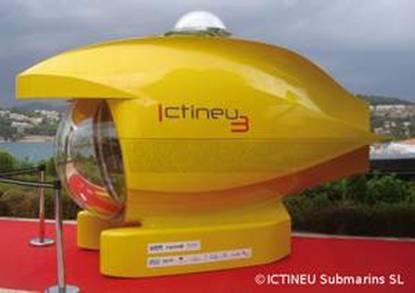
Canadian Navy submarine damage severe.
HMCS Corner Brook hit seafloor off British Columbia in 2011. Slamming into the seafloor at 11 km/h damaged one of Canada's submarines more severely than the navy originally admitted to the public, new documents obtained by CBC show. The Royal Canadian Navy's Damage Assessment and Options Analysis report for HMCS Corner Brook tells a story of a submarine suffering "extensive damage" from "tearing and dents" that left a gaping, two-metre hole in the submarine’s bow. Seawater was "roiling" in the parts of the submarine and two of its torpedo tube doors had been torn off when it rammed the ocean floor off British Columbia two years ago. The submarine had 60 people aboard, including some of the most experienced and senior submariners in the navy, when it rammed the rocky seafloor while cruising 45 metres below the surface. Two sailors were slightly injured during the June 4, 2011 collision.The navy's official board of inquiry blamed Lt.-Cmdr. Paul Sutherland, the sub's captain, for the collision. The inquiry was closed to the public and the navy only released a one-page summary of the hearing. The navy has publicly called the accident a "fender bender" which resulted in no structural damage. But the navy's internal report tells a much different story. The damage report obtained by CBC under Access to Information was completed three days after the grounding and contains photographs detailing the damage to the Corner Brook. While Vice-Admiral Mark Norman, now commander of the Royal Canadian Navy, assured Canadians the damage was not as bad as it looked, the report says "structural state of subsunk." navy shorthand for unknown. "Location of strike likely to have caused shock stress transmission within forward structure," states the navy's early damage report. Norman had denied the damaged extended beyond what could be seen in several photographs obtained by CBC in February 2012. The photos showed the submarine after it was hauled from the water with a hole in it the size of a ping-pong table. "The navy has not been upfront with Canadians about the degree of damage and just how close we came to a truly serious accident. I think the Canadian navy has to come clean across the board with respect to Canada's Victoria class submarines,” said Michael Byers, a University of British Columbia defence expert who has been critical of the submarine program in the past. The report said that there are "strong indications" of damage to the main ballast tank that may extend to the pressure hull of the submarine. The pressure hull is a thick, rolled-steel area of the submarine where sailors live and work. "This accident came very close to claiming the lives of the entire crew,” said Byers, who co-authored a recent report on Canada's fleet of four second-hand British-built submarines.
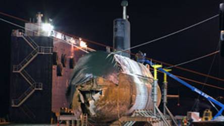
The damage to the HMCS Corner Brook was in the area in which sailors are quartered.
Byers said if the pressure hull is twisted or damaged, it may be impossible for the navy to fix. “Please bear in mind that the documents you have from the ATI request were created very soon after HMCS Corner Brook ran aground in 2011,” wrote Department of National Defence spokeswoman Tracy Poirier in an email to CBC. “While I can say that more work has been done since then to look into what damage the submarine incurred, I have not been able to find out any details as to what was learned during these subsequent surveys.” The navy has said it intends to repair the 2,400-tonne submarine during its scheduled refit period, which is to begin this year and run until 2016. The navy will replace the British torpedo system and other sensors and communications equipment that came with the four Victoria-class submarines Canada bought in 1998. A similar refit process was just completed on another submarine from the class — HMCS Windsor — and it took five years instead of the planned two. The cost of the work on the Windsor totalled $209 million and still only one of the sub's two generators is operational, limiting the distance the sub can go away from land. The navy has not said how much more it will cost to attempt to repair the collision damage to the 70-metre-long Corner Brook. "If it turns out not to have worked after an attempt at repairing the vessel then Canadian taxpayers will have poured close a billion dollars into a bottomless pit trying to recover this submarine," said Byers.
A ‘submarine graveyard’ has been found off the coast of England.
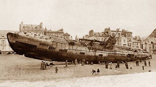
The depths of Falmouth Bay hold many a secret, but none more intriguing than the rust-pocked carcasses of World War I German U-Boats just off Pendennis Point. Salvaged from Scapa Flow in Scotland where the enemy fleet had scuppered itself at the end of the war, the handful of submarines were brought to Falmouth Bay as part of the war reparations scheme. While some were used for target practice, the majority were sunk when a freak storm blew them off their moorings and onto the shore. British archaeologists have discovered more than 40 German U-boats sunk during the first World War. Located just off England’s southern and eastern coast, the subs have been disintegrating for nearly a hundred years. It’s now a race against time to examine the wrecks before they vanish forever.The U-boats were discovered by underwater archaeologist Mark Dunkley along the southern and eastern coasts of the UK. It’s the largest conglomeration of sunken subs ever found, consisting of 41 German U-boats and three English submarines — all from World War I.The subs, all of them near the coast, rest at depths of about 15 meters (50 feet). And because many of the subs sank with crew on board, future expeditions will likely find the remains of sailors inside the wrecks (or “disaster samples” in the parlance of the field).Interestingly, some of the subs have been linked to several U-boats still listed with the German Imperial Navy as missing, including UB 17, a subway crewed by 21 men under the command of naval Lieutenant Albert Branscheid, and the 27-member crew of UC 21, a minelayer commanded by naval Lieutenant Werner von Zerboni di Sposetti.At the start of WWI, there were only 28 U-boats under the command of Kaiser Wilhelm II, a tiny number compared to the Allied fleet. But by the end of the war, the Germans produced some 380 U-boats — half of which were lost at sea.The find could also shed some insight into the war itself. It’s interesting to note that two or three German U-boats were often found lying in close proximity to one another — possible evidence of a certain German combat strategy. By early 1917, the Germans began to target British commercial ships on a large scale. In turn, the Royal Navy reacted by providing freighters with warship escorts, along with airships and aircraft to spot enemy subs from above."We owe it to these people to tell their story," says Dunkley, who works for English Heritage, a public body that is part of the Department for Culture, Media and Sport. Dunkley and his team will explore the wrecks in the coming months. In some cases, they’ll use robotic vehicles to cut open the hatches of the subs to get inside.
China deploys new class of strategic missile submarines next year.
China’s navy is expected to begin the first sea patrols next year of a new class![]() of strategic missile submarines, highlighting a new and growing missile threat to the U.S. homeland, according to U.S. defense officials.“We are anticipating that combat patrols of submarines carrying the new
of strategic missile submarines, highlighting a new and growing missile threat to the U.S. homeland, according to U.S. defense officials.“We are anticipating that combat patrols of submarines carrying the new![]() JL-2 submarine-launched ballistic missile will begin next year,” said one official familiar with recent intelligence assessments of the Chinese strategic submarine force.China’s strategic missile submarine force currently includes three new Type 094 missile submarines each built with 12 missile launch tubes.The submarine patrols will include scores of new JL-2 submarine-launched ballistic missiles (SLBMs) on the Type 094s. The submarines are also called Jin-class missile boats by the Pentagon.The missile submarine patrols, if carried out in 2014, would be the first time
JL-2 submarine-launched ballistic missile will begin next year,” said one official familiar with recent intelligence assessments of the Chinese strategic submarine force.China’s strategic missile submarine force currently includes three new Type 094 missile submarines each built with 12 missile launch tubes.The submarine patrols will include scores of new JL-2 submarine-launched ballistic missiles (SLBMs) on the Type 094s. The submarines are also called Jin-class missile boats by the Pentagon.The missile submarine patrols, if carried out in 2014, would be the first time![]() China conducts submarine operations involving nuclear-tipped missiles far from Chinese shores despite having a small missile submarine force since the late 1980s.The Washington Free Beacon first reported in August that China carried out a rare flight test that month of the JL-2, a missile analysts say will likely be equipped with multiple warheads.That test was carried out in the Bohai Sea near the northeastern coast of China, according to officials familiar with reports of the test.Defense officials said the JL-2 poses a “potential first strike” nuclear missile threat to the United States and is one of four new types of long-range missiles in China’s growing strategic nuclear arsenal.The Air Force National Air and Space Intelligence Center earlier this month published a report
China conducts submarine operations involving nuclear-tipped missiles far from Chinese shores despite having a small missile submarine force since the late 1980s.The Washington Free Beacon first reported in August that China carried out a rare flight test that month of the JL-2, a missile analysts say will likely be equipped with multiple warheads.That test was carried out in the Bohai Sea near the northeastern coast of China, according to officials familiar with reports of the test.Defense officials said the JL-2 poses a “potential first strike” nuclear missile threat to the United States and is one of four new types of long-range missiles in China’s growing strategic nuclear arsenal.The Air Force National Air and Space Intelligence Center earlier this month published a report![]() on missile threats that identified the JL-2 a weapon that “will, for the first time, allow Chinese SSBNs to target portions of the United States from operating areas located near the Chinese coast.” SSBN is a military acronym for nuclear missile submarine.The Pentagon’s most recent annual report on China’s military stated that Beijing’s Navy has placed a high priority on building up submarine forces.In addition to the three Type 094s currently deployed, China will add at least two more of the submarines before deploying a new generation missile submarine dubbed the Type 096, the report stated. It was the first time the Pentagon has revealed the existence of the follow-on strategic missile submarine.“The JIN-class and the JL-2 will give the PLA Navy its first credible sea-based nuclear deterrent,” the Pentagon report said.
on missile threats that identified the JL-2 a weapon that “will, for the first time, allow Chinese SSBNs to target portions of the United States from operating areas located near the Chinese coast.” SSBN is a military acronym for nuclear missile submarine.The Pentagon’s most recent annual report on China’s military stated that Beijing’s Navy has placed a high priority on building up submarine forces.In addition to the three Type 094s currently deployed, China will add at least two more of the submarines before deploying a new generation missile submarine dubbed the Type 096, the report stated. It was the first time the Pentagon has revealed the existence of the follow-on strategic missile submarine.“The JIN-class and the JL-2 will give the PLA Navy its first credible sea-based nuclear deterrent,” the Pentagon report said.
Indonesia prepares for Type 209 submarine construction.
Indonesia is preparing to build facilities in support of local shipbuilder PT PAL's planned licensed construction of the third of three South Korean Type 209 diesel-electric attack submarines, although IHS Jane's understands that the scope of Indonesia's involvement in the programme remains subject to negotiation. The facilities to license-build the submarines, which were ordered from Daewoo Shipbuilding and Marine Engineering (DSME) in December 2011, will be operated by state-owned PT PAL adjacent to its existing industrial plant in Surabaya, East Java. Secondary facilities are also expected to be constructed at the Indonesian Navy base in Palu, on the island of Sulawesi, which is scheduled to be commissioned later this year. The schedule to construct the submarine facilities has slipped several months due to administrative delays, but in a meeting with the Committee for Defence Industry Policy (KKIP) on 11 June, Defence Minister Purnomo Yusgiantoro said in comments published by the Indonesian Ministry of Defence (MoD) that the programme would start "soon". He added that the industrial infrastructure to construct and maintain the submarines will be completed by 2015 or 2016 in line with Indonesia's objective to license-build the third submarine.
Canada’s submarine fleet never worked.
Most Canadians know the sad story of Canada’s second-hand submarines. Purchased from Britain in 1998 for a suspiciously low price, the four vessels have spent most of the last fifteen years being refitted and repaired. What most Canadians do not know is that the “Victoria-class” submarines are now entering the last decade of their service life. And since Canadian naval procurements typically take ten to fifteen years, Canada’s submarine program is destined to splutter to a stop. The problems began in 1994, after the British decommissioned the submarines but left them in saltwater. The vessels languished for four years awaiting a buyer, and another two to six years before Canada actually took possession of them. They suffered serious corrosion and, to this day, the diving depth of HMCS Windsor is restricted because of rust damage to her hull. In 2004, while HMCS Chicoutimi was en route to Canada, a fire broke out on board, leading to one death. The cause of the fire was seawater entering through an open hatch, which caused electrical short. The short occurred because the affected wiring had just one layer of waterproof sealant, instead of the three layers required by the construction specs. That same year, a maintenance error destroyed the electrical system on HMCS Victoria. After the accident, the Halifax Chronicle Herald reported that the Navy spent “about $200,000 to buy old technology that mirrors what the sub’s British builders used,” equipment that one of the Navy’s own “electrical technologists” said “probably goes back to the ‘60s.” The vessel spent six years undergoing repairs. Last year, HMCS Windsor concluded a refit that was initially scheduled to take two years, but took five. Documents obtained by the CBC reveal the reason for the delay: “Every system … has major problems, … including bad welds in the hull, broken torpedo tubes, a faulty rudder and tiles on the side of the sub that continually fall off.” Then, last December, a defect was found in one of HMCS Windsor’s two diesel engines. The CBC reported that, as a result, the vessel’s diving depth was “severely restricted” and the Navy “forced to withdraw the sub from planned exercises off the southern U.S. coast.”Publicly, the Navy insists the submarines can be kept in service until 2030. Behind closed hatches, the admirals must know better. They must be desperate to replace a damaged and unreliable fleet. In 2006, the Senate Committee on National Security and Defence wrote: “The Victoria-class submarines are approaching their mid-life point. As soon as the submarines are fully operationally ready, planning for their mid-life refits and eventual replacement should begin.”In 2010, the Department of National Defence produced a strategic plan, Horizon 2050, that anticipated “the possible re-emergence of inter-state maritime armed conflict … including the possibility that certain states will seek to deny others access to their maritime approaches.” It warned that: “Some adversaries will have the ability to employ more sophisticated area denial capabilities … using ‘high-end’ conventional or asymmetric capabilities such as advanced missiles or submarines.”That same year, a briefing note prepared for the Chief of the Defence Staff argued for new submarines because “in the event of global tensions these relatively cheap assets will counter projection of power and hinder freedom of movement and action.”When Defence Minister Peter MacKay was asked, in October 2011, whether the government might look at replacing Canada’s current submarines, he replied that submarines provide a “very important capability for the Canadian Forces.”Yet curiously enough, there is no mention of submarines in the National Shipbuilding Procurement Strategy, which extends to 2041 and foresees the expenditure of $33-billion on dozens of surface vessels. The omission cannot be excused on the basis that any new submarines would be built outside Canada and therefore fall outside the scope of the shipbuilding strategy. For two of the available options – the French-designed Scorpene and the German-designed U-214 – are already being built in countries that have purchased them. But there are three possible explanations. First, the Harper government has already decided to acquire new submarines, and is keeping the decision quiet because of the billions of dollars that would cost. Second, the government has decided to terminate Canada’s submarine program when the Victoria-class vessels reach the end of their service lives, and is keeping that decision quiet because of the billions of dollars it has already spent trying to rescue a failed procurement. The third and most likely explanation is gross mismanagement of the file. And if that is the case, the lack of a plan will result in the end of Canada’s submarine program – through neglect and obsolescence, rather than design.
Upgraded Alvin Sub Heads for West Coast. |
On 25 May 2013, the R/V Atlantis will leave Woods Hole carrying the upgraded submersible Alvin, marking a major milestone in the sub’s USD41 million redesign. Both ship and sub are owned by the U.S. Navy and operated by the Woods Hole Oceanographic Institution (WHOI) for the benefit of the entire U.S. ocean science community. They are expected to reach Astoria, Oregon, on 20 June 2013. |
In September 2013, Alvin will undergo the Navy certification process, making a series of progressively deeper dives off Monterey, California, USA. Once certified, the sub will be put through its paces in a science verification cruise in November 2013 to ensure all of its scientific systems are operational. Alvin is scheduled to return to service in December 2013. Funded by the National Science Foundation (NSF) and WHOI, the planning process for the sub’s upgrade began over a decade ago. In 2005, work was begun by Southwest Research Institute to design and forge a new titanium personnel sphere, one of the biggest technical challenges in the Alvin upgrade project. The sphere, which holds a pilot and two scientists, is designed to descend to 6,500 metres (21,000 feet or 4 miles) – depths that generate nearly 10,000 pounds per square inch (psi) of pressure on the sphere. Construction of the sphere, which has 3-inch-thick walls, required more than 40,000 pounds of titanium. Identical hemispheres were forged and then welded together with an electron beam. Its interior diameter is 4.6 inches wider than Alvin’s previous sphere, increasing the interior volume from 144 to 171 cubic feet. With five viewports, it also has improved and overlapping fields of view for the pilot and scientists allowing for better observations and collaboration in selecting sampling sites. The personnel sphere underwent hydrostatic pressure testing in June 2012, and was successfully tested to the equivalent of 8,000 metres water depth. Although the new sphere is rated to depths of 6,500 metres, the sub’s dives will be limited to 4,500 metres until a second phase of the upgrade can be completed. Phase two hinges on the development of improved lithium ion battery technology and funding. Improvements made to the submersible during the Phase one upgrade include:
Additional improvements were needed to the R/V Atlantis to accommodate the larger, heavier sub. Among the ship’s upgrades were a strengthened A-frame, which is used to launch and recover the sub, and alterations of the hangar where the sub is stored when not in use. The world’s longest-operating deep-sea submersible, Alvin was first launched in 1964. It has made 4,664 dives and played a role in a number of important deep-sea discoveries. Its most famous exploits include locating a lost hydrogen bomb in the Mediterranean Sea in 1966, exploring the first known hydrothermal vent sites in the 1970s, and surveying the wreck of RMS Titanic in 1986. Its final series of dives before the current upgrade period were in the Gulf of Mexico exploring deep-sea biological communities near the site of the Deepwater Horizon blowout and oil spill.
|
Scandinavia’s nuclear threat: Where are the 130 operating reactors?
Elena Vasilieva – an expert at the All-Russian Institute of Environmental Expertise (“Eco Ex”) – confirmed the aforementioned figures in the report “Nuclear Kola Peninsula”, in which she calls the Murmansk region the world-leader in terms of nuclear facilities. The greatest threat to the inhabitants of Murmansk and Scandinavia, however, is the Russian Navy’s Red Banner Northern Fleet which is based on the Kola Peninsula. This nuclear submarine fleet is one of the most powerful of its kind in the world, with nuclear reactors and nuclear warheads on board. Nuclear submarines began to appear in the Murmansk region from the 1st of July 1958, which saw the transfer of the nuclear submarine K-3 “Leninskii Komsomol” to the Northern Fleet. Today, the Northern Fleet includes the following types of Nuclear Powered Submarines (NPS):
- Ballistic Missile Submarines (different classes): Project 941 “Akula”, “Dmitry Donskoy”, “Arkhangelsk” (in reserve), “Severstal” (in reserve) – with two reactors with heat capacities of 190 megawatts each. Also, Project 667BDRM “Dolphin”, “Verkhoturye”, “Yekaterinburg”, “Tula”, “Bryansk”, “Karella”, “Novomoskovsk” – with two reactors each, with total heat capacity of 180 megawatts.
- Submarine-launched missiles: Project 949A “Antey”, “Voronezh”, “Smolensk”, and “Orel”, with tow reactors of 190 megawatts each.
- AKULA 1-class SSN: Project 971 “Schuka-B”, “Pantera”, “Volk”, “Leopard”, “Tigr”, “Vepr”, and “Gepard”, with on reactor with a capacity of 190 megawatts.
- SIERRA 1-class SSN: Project 945 “Barracuda” and “Kostroma” with one reactor of 180 megawatt capacity; Project 945A “Condor”, “Nizhny Novgorod”, and “Pskov” with one reactor of 190 megawatt capacity; Project 671-RTMK “Pike”, “Petrozavodsk”, “Obninsk”, “Daniel Moskovsky”, and “Tambov” with two reactors with a total capacity of 144 megawatts.
- Special-purpose submarines – nuclear deep-water stations: Project 667BDRM “Orenburg” with two reactors with a total capacity of 180 megawatts; Project 667BDRM “Del’fin” BS-64 with two reactors with a total capacity of 180 megawatts; Project 1910 “Kashalot” AC-16, AC-19 with one reactor of 15 megawatt capacity; Project 1851 “Paltus” AC-23, AC-21, AC-35, which has a capacity of 10 megawatts per reactor.
In addition to this, there are three nuclear-powered missile cruisers “Admiral Ushakov”, “Peter the Great”, and “Admiral Nakhimov”, all with two reactors with a capacity of 300 megawatts each. The total strength of the Northern Fleet is comprised of 54 operating reactors with a total capacity of 7912 megawatts. To put this in perspective, the total power generated by the Kola Nuclear Power Plant (NPP) is only 1170 megawatts. There are at the present moment seven nuclear power stations adrift in the Barents Sea – the danger and possible consequences of such a situation are far greater than those presented by any terrestrial power plant. Statistics concerning accidents and sunken nuclear-powered submarines would appear to confirm this risk – most accidents occur in the Northern Fleet.
- In 1968 – an accident occurred with the nuclear submarine K-27, killing nine people.
- In 1982 – a boat was flooded with nuclear fuel spilling from two reactors intended for disposal in the KaraSea
- In 1970 – an accident occurred with the nuclear submarine K-8. The resulting fire in two of the submarine’s compartments killed 52 people. It sank in the Bay of Biscay.
- In 1986 – an accident occurred with the nuclear submarine K-219 as a result of the explosion of a rocket in one of the mines. Four people were killed. The submarine sank near Bermuda in the Atlantic Ocean.
- In 1989 – a fire started during combat duty on the nuclear submarine K-278 “Komsomoletz”, killing 42 people. The submarine sank in the Norwegian Sea.
- In 2000 – an accident occurred on the nuclear submarine K-141 “Kursk”. A torpedo boat exploded during manoeuvres in the Barents Sea. All 118 crew members were killed.
- In 2003 – an accident occurred on the nuclear submarine K-159 while it was being towed for disposal. It sank, killing nine people.
The list above does not even take into account accidents occurring on nuclear facilities which were not related to flooding: K-19 in 1961, K-8 in 1960, K-123 in 1982, K-129 in 1989 and many more. By way of comparison, only two nuclear submarines have sunk in the USA. All such incidents result in radioactive spills into the marine environment. Danger is also present in the fact that nuclear submarines carry nuclear charges. Two of the sunken submarines (K-8 and K-278) were carrying torpedoes with nuclear warheads. Only one submarine “Dmitry Donskoy” (a TYPHOON class SSBN) is equipped with the missile complex “Bulava” – six hypersonic warheads with a capacity of up to 150 kilotons each. By way of comparison, the power of the atomic bomb, “Little Boy”, which destroyed the city of Hiroshima on the 6th of August 1945, was just 18 kilotons. The explosion of just one of the warheads of the “Dmitry Donskoy” is capable of destroying all marine life in the Barents Sea, rendering it completely unsuitable for human use. Not to mention the potential damage to coastal settlements. The use of these nuclear submarines and surface ships is always accompanied by the threat of nuclear contamination in the Barents Sea. There is no such thing as a safe nuclear reactor. Their use, even in normal mode, leads to the inevitable formation of radionuclide atoms, which are subsequently released into the environment. It is first of all necessary to look at tritium, its destructive influence on the genetics of living organisms and its ability to penetrate through all of the reactor’s protective layers. Not to mention the short- and long-lived radionuclide atoms and several other unknown and devastating consequences connected to the use of nuclear reactors. This is nature’s compromise – its gift to humanity of this huge power and energy comes at the ultimate cost of its own heath and life. The release of radionuclide atoms is taking place both at the surface and at various depths of the Barents Sea where nuclear submarines are permanently stationed: Zapadnaya Litsa, Gadzhievo, Polyarny, Vidyaevo, Gremikha, and Yokanga; in Guba Okol’naya, where missiles with nuclear warheads are loaded onto submarines; at the technical base for the Northern Fleet in Yokanga, where spent nuclear fuel is stored; in Zapadnaya Litsa, where radioactive waste is stored; and on the four ships engaged in nuclear service for the Northern Fleet, where there is both fresh and spent nuclear fuel and radioactive carriers. The “Nuclear Kola Peninsula” is comprised of nuclear-powered ice-breakers: “Russia”, “Soviet Union”, “Yamal”, “Fifty Years of Victory”, each with two reactors. Icebreakers – “Taimyr” and “Vaigach”, each with one reactor. Situated in the sediment are the nuclear ice-breakers “Lenin”, “Arctic”, and “Siberia”, each with two reactors. The floating base “Lepse” which holds spent nuclear fuel and radioactive waste, has become a global environmental problem. The total number of documented operating nuclear reactors stands at seventy, including ten vessels which are retired, spare or under repair. Data on the remaining 130 nuclear reactors, their location and their usage is basically non-existent. Given the past and present nuclear disasters, the more or less restricted access to information in the publications of the Russian State Agency on nuclear energy sources is insufficient for the purposes of Russian and international ecological organisations (and others) who wish to control nuclear energy. Part of the next instalment of the article series “Scandinavia’s nuclear threat” will be dedicated to the secret and mysterious nuclear facilities of the Kola Peninsula.
CIA Declassifies Recovery of Spy Satellite by The Trieste submersible.
 The second mission of its kind was recently declassified by the U.S. Central Intelligence Agency (CIA), releasing documents regarding the collection of a Cold War-era spy satellite. Reaching a depth of 16,400 feet, the 1972 operation in the Pacific Ocean was the deepest recovery effort ever attempted at that time. The CIA's Historical Collections Division gave a presentation at the Naitonal Museum of the United States Navy on April 25 detailing the mission. Navy personnel who were a part of the project offered first-hand accounts of how the satellite was located and recovered. In July 1971, the Hexagon, a film-return satellite, lost one of its buckets as a parachute detached from the container and sent it plunging into the Pacific. The Navy's USS Trieste II, the only vessel with the capability to complete the recovery mission, began searching for the lost bucket in October of that year, along with its support ship and tug. Nine months after the satellite sank, the Trieste was able to pull part of the film container from the ocean. The bucket hit the ocean floor with such force that only 25 feet of film was recovered. The impact was so great that paint from the structure was transferred to the film, creating the sole image collected from the satellite, which showed only the number 300. The film was suspected to have contained images of denied areas that would have helped to determine an arms control regime between the U.S. and the USSR. The mission proved that deep-sea recovery was possible at a depth encompassing 80 percent of the world's oceans.
Vietnamese Submarines.
The first two of six submarines for Vietnam are being completed in Russia. Due for delivery at the end of October 2013. The crews are being trained in Russia for operations, and in India for evacuation procedures.
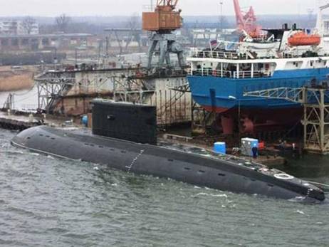
|
Prime Minister Nguyen Tan Dung inspects the progress of Viet Nam's Kilo-class submarine, which is being tested in Kaliningrad, Russia. |
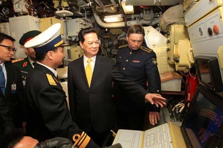
This is the first of six Kilo-class submarines that Viet Nam contracted to buy from Russia during Dung's visit to the country in 2009. Under the contract, the Russian side is also responsible for training sailors and supplying necessary equipment for the submarines. The Kilo-636 submarine, named Ha Noi, was built in Admiralty Verfi Shipyards in St Petersburg and is being tested near Svetlyi port in Kaliningrad. It has successfully made 23 test dives. Having a displacement of 3,000-3,950 tonnes, the submarine can operate at a maximum depth of 300m and at a range of 6,000-7,500 nautical miles for 45 days and nights with a crew of 52. It is said to have the quietest engine in the world, a great choice for reconnaissance work and patrols.
|
|
Talking with sailors on board, the PM said he hoped they rapidly grasped the modern technology so they can master the vessel after it is transferred to Viet Nam. Captain Major Nguyen Van Quan thanked the Party, State and people for their care for the crew. Later, Dung told the Russian media that Kaliningrad was such a peaceful and hospitable city. He said the Vietnamese people would never forget the support that Russia had given them during their past struggle for independence. He said Russia's supply of submarines to Viet Nam was not only a trade deal but also reflected the friendship between the two countries.
Israel Navy launches $500m Dolphin submarine.
This submarine, the most expensive weapon ever procured by Israel, can carry nuclear missiles according to foreign reports. Israel Navy Commander Vice Admiral Ram Rotberg and Ministry of Defence director general Udi Shani today launched the new Dolphin submarine at Kiel Port in Germany. The submarine, named "INS Rahav", will cost $500 million, one third of which will be financed by Germany. The INS Rahav is the most expensive item ever procured by the Ministry of Defence. The INS Rahav will arrive in Israel in one year, after completing tests and is declared operational. The Navy and Ministry of Defence said that the INS Rahav is one of the most advanced submarines in the world, and that its long-range secret mission capability would extend the IDF's operational capabilities. According to the foreign media, the Dolphin-class submarines can also carry nuclear missiles. Israel will receive the sixth Dolphin-class submarine, also built by HDW Shipyards GmbH, in a few years. The defence establishment calls this cutting-edge submarine an "improved Dolphin". It will reportedly be delivered to the Navy in 2017 or 2018, and will also cost $500 million. The Navy does not talk much about the operations of its submarine fleet, which the defence establishment calls "Israel's very long arm". Former Navy Commander Vice Admiral (res.) David Ben-Bassat once told "Globes", "Doubling the submarine fleet will reflect Israel's recognition of the strategic depth of its maritime space and will give the Navy immense capabilities. The IDF's defence concept will be significantly improved and upgraded when it receives more submarines." Israel developed many of the Dolphin submarine's systems. Defence sources say that Germany is making reciprocal procurements from Israeli civilian and defence companies as part of the program.
€530m bill for Spain's 'sinking submarines'
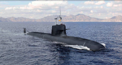
A defence contract worth €2.2 billion has hit the rocks after tests showed that the "world's most modern" submarine would plunge straight to the bottom of the sea. Spain just spent $680 million on a submarine that can’t swim. One of Spain’s largest defense splurges may also be one of its most embarrassing. After spending nearly one-third of a $3 billion budget to build four of the world’s most advanced submarines, the project’s engineers have run into a problem: the submarines are so heavy that they would sink to the bottom of the ocean. Miscalculations by engineers at Navantia, the construction company contracted to build the S-80 submarine fleet, have produced submarines that are each as much as 100 tonnes (110 US tonnes) too heavy. The excess weight sounds paltry compared to the 2,000-plus tonnes (2,205 US tonnes) that each submarine weighs, but it’s more than enough to send the submarines straight to the ocean’s floor. Given the mistake, Spain is going to have to choose between two costly fixes: slimming the submarines down, or elongating them to compensate for the extra fat. All signs point to the latter, which will be anything but a breeze—adding length will still require redesigning the entire vessel. And more money on top of the $680 million already spent. Spain’s defense ministry, the government arm responsible for overseeing the project, has yet to say how much the setback will cost in both time and money. But Navantia has already estimated that its mistake will set the project back at least one or, more likely, two years. And the Spanish edition of European news site The Local reported that each additional meter added to the S-80s, already 71 meters in length, will cost over $9 million. It’s a costly mistake on many fronts. The state-of-the-art submarines were meant to be the first entirely Spanish-designed and built. Incompetence is likely going to cost the country at least some of the glory. Electric Boat, a subsidiary of US-based technology firm General Dynamics, has already evaluated the project and could be hired as a consultant to save the job.
Yellow Submarine.
Old nuclear submarines to be scrapped.
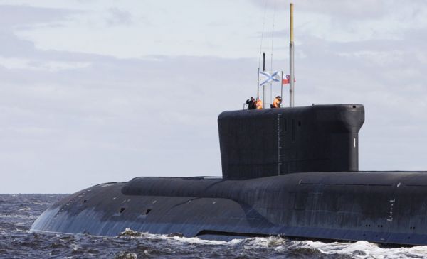
A new Russian nuclear submarine, Yuri Dolgoruky, seen in the water area of the Sevmash factory in the northern city of Arkhangelsk, Russia, 2 July, 2009. Russia will decommission and scrap two Cold War-era nuclear submarines, a navy official said on 21 May. The official told RIA Novosti the submarines, among the largest ever made, are too old to remain on active duty and too expensive to retrofit. The Severstal and the Arkhangelsk, both Project 841 (Typhoon-class) ballistic-missile submarines, based at Severodvinsk on the White Sea, will be withdrawn from the Navy by the end of 2013 and will begin to be dismantled. “This process is to be completed before 2018-2020 at the latest,” the source said. A third submarine of this class, the Dmitry Donskoy, has been modernised as a test platform for Russia’s new Bulava submarine-launched ballistic missile, and will remain in service in that capacity for some time yet, the source said. Six Typhoon-class submarines entered service with the Soviet Navy in the 1980s, and remain the largest submarines ever built. Three have already been scrapped.
Teenager Builds Submarine Nautilus, Maybe North Korea Will Be Afraid?
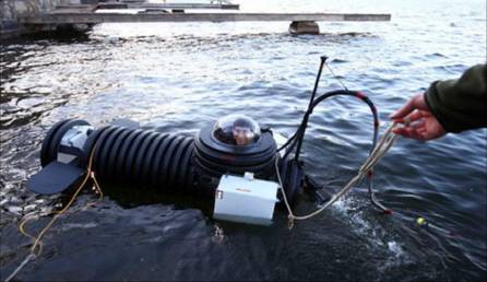
When American teenagers build submarines named after nuclear subs, maybe North Korea will be afraid of invasion? More seriously, eighteen-year-old Justin Beckerman has created a remote controlled cleaning machine, an airsoft car, and a helmet home theater. Now this teenager has built a submarine that can dive as deep as thirty feet. This teenager who builds submarines explains his motivation: “I wanted to see what I could build and figure out how I could build it. … It’s just going to be cool to be underwater.” Justin Beckerman spent six months building the submarine in his parents’ basement for an estimated cost of $2,000. This teenager’s custom built submarine is named the Nautilus after the USS Nautilus, the world’s first nuclear submarine. But Kim Jong-Un need not overly worry. The body of the submarine is made from a giant drainage pipe, the motor from a small fishing oat, and the dome is a sky light. Ballast tanks allow this teenager’s submarine to dive and rise. An audio and video based communications system and ultra-bright lights allow Justin Beckerman to explore the depths of his local lake. Then again, that sounds about as advanced as some of the photoshopped pictures from North Korea. Justin Beckerman’s parents were obviously concerned about safety since the original submarines tended to sink rather than swim. Although this teenager built his submarine essentially out of spare parts, he’s not very concerned: “There are a lot of safety features. There are pumps. There’s also a breathing hose so that if it does flood, you could breathe for about 20 minutes or so off of a tank of air.” What do you think of this teenager building his own submarine called the Nautilus?
Royal Navy diver's logbook offers fascinating insight into life on World War One submarine that sank.
The forgotten logbook of a former Royal Navy diver has revealed fascinating details about a unique World War One submarine that sank over 80 years ago as the result of a simple failure to secure the door. The faded diary of Plymouth-born Albert ‘Bob’ Smale who, as a 23-year-old recently-qualified Navy Diver participated in a year-long salvage operation to raise the world’s very first underwater aircraft carrier, HMS M2, has been found by his family. Lee Smale, 62, of Plymouth, Devon, the youngest son of four children born to Bob and Gladys Smale remembers his father’s logbook from childhood. The forgotten logbook of a former Royal Navy diver Bob Smale by his son Lee (pictured) has revealed a fascinating insight into attempts to raise a unique World War One submarine that sank over 80 years ago
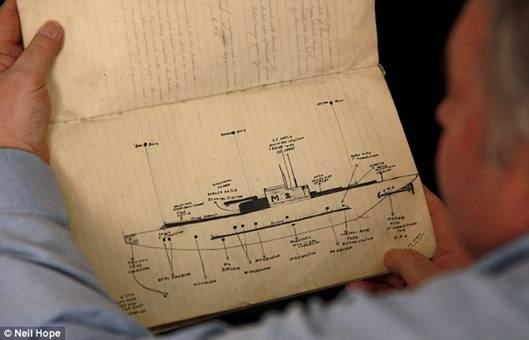
The fading diary was rediscovered by the family of Plymouth-born Naval diver who participated in a year-long salvage operation to raise the world's very first underwater aircraft carrier, HMS M2.

It reveals that the World War One submarine that sank over eighty years ago as the result of a simple failure to secure the door . All of the vessel's 60-strong crew lost their lives in the tragedy - believed to be a direct consequence of a failure to secure the submarine's hangar doors before diving. 'The logbook had always been in the family but it we’d never really given it much thought,' he said. 'He died in 1968 but it was only when we began sorting through my mother’s things when she moved into sheltered accommodation that it resurfaced. 'But looking through all his belongings and coming across the logbook again the family recognised its significance.' The M2 was one of four ‘M’ class submarines put into service during WW1 and following the cessation of hostilities was modified to carry a small two-seater Parnell Peto biplane. Intended for aerial reconnaissance during advance scouting missions, the aircraft had hinged wings to allow it to fit within a specially designed watertight hangar. Launched by hydraulic ‘catapult’ the Peto, on its return was recovered via a deck-mounted crane. As a 23-year-old recently-qualified Navy Diver he participated in a year-long salvage operation to raise the world¿s very first underwater aircraft carrier. On January 26, 1932 during a routine training exercise off West Bay, Dorset, after advising her support vessel of her intention to dive, all contact with the M2 was lost and the submarine disappeared without trace. A major search ensued but with her position unknown it was eight days before the M2’s location was eventually discovered. All of the vessel’s 60-strong crew lost their lives in the tragedy - believed to be a direct consequence of a failure to secure the submarine’s hangar doors before diving. Lying upright on the seabed at a depth in excess of 30 metres, the Royal Navy salvage team, hindered by the strong tidal currents that swirled around the M2, worked around the clock for 11 months to seal the hull prior to filling the vessel with air to refloat the stricken submarine. But as the salvage attempt reached its final stage, and only six metres from the surface, a heavy gale resulted in the operation being aborted and the M2 dropped back down to the seabed. The neat handwritten pages of the logbook initially record Mr. Smale’s diver training, but further examination revealed a passage dedicated to the M2 salvage work carried out by himself and his colleagues. Under a heading entitled 'M2 Salvage” Mr. Smale describes the 'method of sealing hatches with cement.' 'Hatch is closed down and then a layer of small bags filled with cement is placed on top, and then a few buckets of loose cement is put on to fill in the spaces between bags.' The logbook also contains a detailed hand-drawn illustration of the submarine showing its position, features and amendments prior to the failed lifting operation. The difficulties of working at such a depth, contending with strong tides, poor visibility and bad weather while dressed in the heavy brass helmets of the era are also conveyed in detail in a collection of newspaper cuttings pasted among the book’s pages. The Dorset Daily Echo reported: 'He has an electric torch swung around his neck. 'The feeble illumination of this helps him when the torch is held close, but his principal asset is a sense of direction acquired by experience and that astonishing sensitiveness of touch which utter darkness gives to a diver as to a man who is blind.'
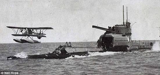
The M2 was one of four ¿M¿ class submarines put into service during WW1 and following the cessation of hostilities was modified to carry a small two-seater Parnell Peto biplane. Pictured is the HMS M2 in action.
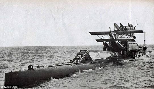
Intended for aerial reconnaissance during advance scouting missions, the aircraft had hinged wings to allow it to fit within a specially designed watertight hangar.
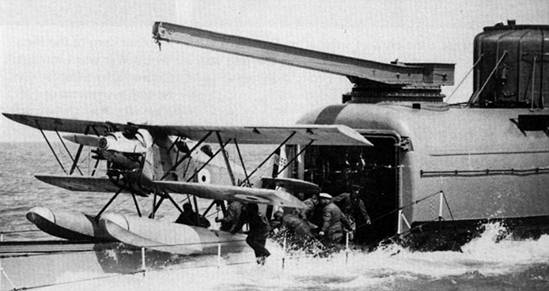
Launched by hydraulic 'catapult' the Peto, on its return was recovered via a deck-mounted crane.
'My dad had quite a varied and distinguished career,' continued Lee who also has a certificate in recognition of his father’s mention in dispatches during the Wanhsien Incident on the Yangtze River, China in 1926. Bob Smale was a contemporary and close friend of Lionel 'Buster' Crabb (pictured), the Royal Navy frogman who disappeared in mysterious circumstances at the height of the Cold War. Going on to achieve the rank of Petty Officer, Bob Smale was a contemporary and close friend of Lionel ‘Buster’ Crabb, the Royal Navy frogman who disappeared in mysterious circumstances at the height of the Cold War. Lieutenant Commander Crabb, came to prominence for his pioneering work in underwater bomb disposal during WW2 and while he had all but retired by 1955 just a year later he was recruited by M16 to investigate an advanced propulsion system used by the Soviet cruiser Ordzhonikidze during the vessel’s visit to the United Kingdom. On the evening of April 19, 1956 Crabb descended into the murky waters of Portsmouth Harbour on what was to be his final mission and was never seen again. Several months later the headless and handless corpse of a diver was discovered floating in a nearby harbour, but this was not the end of Commander Crabb’s story. At the inquest into Crabb’s disappearance, the coroner’s report suggested that the body was in all probability that of the missing 47 year-old OBE and George Medal holder - despite to the lack of firm evidence which could have been provided by fingerprints or dental records. Unsurprisingly various theories abounded as to Crabb’s fate: he was killed by a Soviet sniper; eliminated by M15 or even defected to the USSR to head their military diving team. With her protected status as a War Grave, the wreck of HMS M2 has now become popular dive site with recreational scuba divers. Allowed to dive her remains on a 'ook-but-don't-touch' basis, the modern day diver can observe the M2's final resting place, just as Bob Smale did over eighty years ago. However, Lee Smale is adamant that his father’s friend didn’t die on that fateful night. 'He and my father were apparently very close and he told members of the family at the time that he didn’t believe for one minute that Crabb was dead.' With her protected status as a War Grave, the wreck of HMS M2 has now become popular dive site with recreational scuba divers. Allowed to dive her remains on a ‘look-but-don’t-touch’ basis, the modern day diver can observe the M2’s final resting place, just as Bob Smale did over eighty years ago.
Migaloo Submarine.
Designers build latest toy for the super-rich: the 115m submarine yacht with helipad and a swimming pool that moves below deck when submerged. The vessel has been named Migaloo after an albino whale. Designers came up with concept to satisfy demand from super-rich. If you're a Bond villain - or just super-rich - you could be in the market for one of these. Here is a yacht that will give any owner that sinking feeling - because it is also a submarine. Austrian-based yacht design studio Motion Code: Blue developed it as a design study of a six deck, 115 metre long private white yacht, called Migaloo and named after an albino whale. The studio came up with an extraordinary design concept to satisfy the ever raising demands from super-rich yacht owners who want to stand out from the crowd.
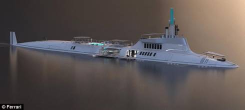
The yacht that's also a submarine: The Austrian-based yacht design studio Motion Code: Blue developed it.
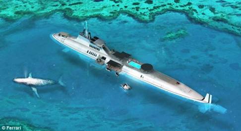
The studio came up with an extraordinary design concept to satisfy the ever raising demands from super rich yacht owners who want to stand out from the crowd. The hull of the 11 metre wide Migaloo is identical to current submarines. Only the tower is custom designed, which means it is longer and wider to host a light flooded main room followed by a wide staircase including a centered , round elevator shaft. The enormous aft deck allows for lounge areas, sun beds, a bar, an 8 metre by 3 metre pool as well as a helicopter pad. When Migaloo is submerged, all furniture is put away in large storage areas underneath the granite decking while the pool's bottom raises up to the main deck level. The foredeck is fully dedicated to the owners' privacy, hosting a full-beam private lounge. More lounge areas, a private bar and access to the two-level-owners' suite are directly underneath the foredeck. A telescopically extendible roof provides shade and follows perfectly the contour lines of the hull when closed.
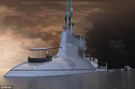
The hull of the 11 meter wide Migaloo is identical to current submarines. The company says it's very likely to travel amongst school of whales heading into the deep while having a cup of tea and a good chat in the main saloon. The hull and tower are equipped with large windows of special pressure-proof glass to offer a breathtaking view especially when Migaloo is submerged. A spacious sun lounge on top of the tower completes the common amenities onboard a super yacht. The lounges are accessible via two wide stairways from the main deck or from all interior deck levels via the lift. The telescopically extendible roof provides shade and will also be closed when the owner prefer to dive with the yacht. For the crew, the design studio has planned an outdoor helm station on the forward top of the tower when the vessel travels above the water line. Otherwise the spacious bridge and all necessary technical rooms hosting the equipment to control the submarine are right underneath the tower in the hull. The hull's design and dimensions are inspired by existing submarines. They are aid to offer extra ordinary space for the owner and his guests, which are accommodated in eight VIP-suites on sub-decks two and three. The design studio has planned an outdoor helm station on the forward top of the tower when the vessel travels above the water line. The spacious bridge and all necessary technical rooms hosting the equipment to control the submarine are right underneath the tower in the hull The owner has his or hers private-full-beam-quarters over two decks on sub-deck one and sub-deck two. Other luxury appointments include a cinema room, a library, a gym and a gaming room. Four wide side hatches two on each side, can be transformed into enormous beach terraces. A spacious dining area next to the saloon on sub-deck one and the adjoining beach terrace give luxurious access to the water. Lounges and a Jacuzzi enhance this area while a comfortable ladder connects the beach club with the main deck above for easy access to the water on these two decks. Removable sun sails on each deck guarantee pleasant sun protection. All tenders and toys can be stored in the beach club or on the deck below, so the transport of a wide range of additional vehicles is possible. Sub-deck four is entirely reserved for the crew quarters including crew mess, laundry and crew gym while the main galley is positioned on sub deck two underneath the dining room. The hull and tower are equipped with large windows of special pressure-proof glass to offer a breathtaking view especially when Migaloo is submerged. All windows are surrounded with underwater lights to provide stunning views when the yacht goes deeper. Communication and especially navigation is provided by common and well tested technologies and the hull is designed to reach a maximum depth of 240 metres. The company says it's very likely to travel amongst school of whales heading into the deep while having a cup of tea and a good chat in the main saloon. A spokesman for Motion Code:Blue said: 'Migallo was the result of intense research and the firm's excellent knowledge of the current yacht market. 'An increasing number of clients have exactly such special demands on the design as main points in their briefing for their designers, so the studio's intention was to offer a stunning design concept especially for people who are willing to expand the borders of imagination.' Managing directors Christopher Gloning and Christian Gumpold had the original idea which was, to transform the well known and tested shape of current submarine designs into a private yacht. They wanted it to offer state-of-the-art luxury experience of same sized super yachts while having the huge benefit to submerge the whole vessel to travel and/or stay secretly and in total privacy underneath the waterline without any external disorders. The studio has recently completed several projects featuring both production yachts and super yachts currently under construction and has worked for yachts in Asia, Europe and the USA.
Deepsea Challenger Headed for WHOI.
While he works on his next film, James Cameron has not only left his Deepsea Challenger to the Woods Hole Oceanographic Institution (WHOI) of Woods Hole, Massachusetts, he has also given them about $1 million in a growing partnership to advance marine exploration. The Deepsea Challenger's camera and lighting system is able to take high-resolution, 3D pictures at depths with little to no visibility. This system will be installed in one of WHOI's vessels, the Nereus, as it prepares for a 2014 expedition to the Kermadec Trench, 10 kilometers below the surface of the Pacific Ocean. The U.S. National Science Foundation is funding the project, which will cost more than $1 million for the six-week venture. Trenches below 6 kilometers deep are a relatively unexplored area of the oceans. The high pressure in these regions require subs that are designed for the environment. The structure of the Deepsea Challenger has materials engineered to add strength to the hull without adding weight to the vessel. It also has a pressurized cockpit and system for converting moisture from the pilot's breath and sweat into drinking water. Cameron has stressed the importance of helping scientists research the ocean floor through first-hand experiences, but unmanned vehicles will most likely be necessary as well for the exploration of trenches. the Deepsea Challenger is set to arrive in Massachusetts in June. The vessel is scheduled to come right after WHOI's new Center for Marine Robotics opens, a department geared toward researching marine technology.
Submersible videotapes deep-sea life in South China Sea.
High-definition video images acquired by Chinese submersible Jiaolong show brown mussels dotting the area around the cold vent some 1,500 meters under water during its manned dive mission in the South China Sea, scientists said Tuesday. Zhou Huaiyang, professor of the School of Marine and Earth Science at Tongji University, became the first scientist to work on the sub as a crew member during a dive conducted on Tuesday. Zhou said the quality of the images obtained during the dive is the best ever achieved in extreme oceanic conditions using domestically produced equipment. "The discovery of multiple sea bed dwellers, such as mussels and pilumnus crabs, will help to support further research concerning the deep-sea biosphere, gas hydrate resources and climate change," Zhou said. A cold vent is an area of the ocean floor where hydrogen sulfide, methane and hydrocarbon-rich fluid seepage occurs, according to Feng Dong, a researcher from the South China Sea Oceanic Institute under the China Academy of Social Science. "Cold vents are a current focus in scientific circles, as they can give us information on potential gas hydrogen resources, climate change and extremophilic organisms," Feng said. The Jiaolong's cold vent samples will help support research on deep-sea biospheres, according to Feng. Scientists have described the Jiaolong manned deep-sea submersible's role in oceanic research as being of great significance following Monday's commencement of a four-month trial mission. The submersible also completed a deep-sea dive in the South China Sea on Monday. It was unloaded from the Xiangyanghong 09 oceanographic vessel and began its dive around 10 a.m., returning to the vessel around 4:30 p.m. The submersible and its crew of three dove to a depth of about 1,400 meters during the dive. The crew included Ye Cong, chief designer of the Jiaolong and an employee of the China Shipbuilding Industry Corp., Yang Bo, a researcher from the Institute of Acoustics under Chinese Academy of Sciences (CAS) and Liu Kaizhou from the Shenyang Institute of Automation under the CAS. Liu Feng, chief commander of the mission, said the success of the dive confirmed the submersible's ability to perform reliably. "We arrived at a sea bed located at a depth of 1,400 meters, then moved uphill until we found a cold vent," said Ye, who also piloted the craft. The Jiaolong has an edge in accurate sampling, as its mechanical arms enable it to collect samples more precisely, said Yang Qunhui, a professor from Tongji University. "We expect that the Jiaolong can be used to cultivate biological samples on the sea bed, as the high pressure and temperature of the deep sea make it an ideal environment for in-situ cultivation," Yang said. In June last year, the submersible set a new dive record after reaching a depth of 7,062 meters in the Pacific Ocean's Mariana Trench. The current mission marks the start of a five-year trial period for the Jiaolong before it goes into regular operation. The submersible left the city of Jiangyin in east China on Monday to begin a 113-day-long mission that will include experiments designed to test its positioning system, as well as biological surveys and geological sampling to be conducted in the Pacific Ocean.
ALVIN REFIT.
Over the course of 4400 dives, Alvin has done just about everything. Its recovered lost nukes, explored the ruins of the HMS Titanic, and upturned our understanding of the deep sea with the discovery of hydrothermal vents bustling with unimaginable forms of life. But after 48 years of service, the venerable ROV is starting to show its age, and is quickly being eclipsed by newer models. That’s the story, at least, until Alvin gets $US40 million in upgrades and becomes the world’s premiere deep submergence vehicle once again. Alvin is the longest-serving deep submergence vehicle (DSV) on Earth. When it first entered active service in 1964, Alvin was nothing short of revolutionary. Designed as a replacement for earlier, less-mobile bathysphere technologies, the 7m long, 15-tonne manned submersible offered researchers the unprecedented opportunity to explore 4500m below the surface. Its 1.8m diameter personnel sphere offered just enough space to cram in two researchers and a pilot, while a trio of 13 cm-wide viewing ports allowed for at least a bit of scientific rubbernecking. However, as Cindy Van Dover, a former Alvin pilot describes to Nature, “sometimes it was a great view, but often it wasn’t, so you’d end up watching a video of what the pilot was doing.” And in the past few years, France, Russia, Japan, and China have all fielded research vessels with capabilities exceeding Alvin’s. Well, that just won’t do. The Woods Hole Oceanographic Institution (WHOI), operators of the Navy-owned vessel, is currently in the first of a two-phase, $US40 million upgrade to bring Alvin back up to par. This first phase, scheduled to be completed by the end of this year, will include a bigger personnel sphere, cut from 15.5 tons of titanium with 18 per cent more interior space. Three new 18cm viewing ports will join the existing set. Researchers will be able to record more of their dives thanks to the addition of high-output lighting and HD cameras as well as a new work basket that effectively doubles its carrying capacity. Alvin will be more manoeuvrable as well, receiving a new command and control system, stronger thrusters, as well as revamped syntactic foam — which provides buoyancy and structural rigidity when compressed at depth. When Phase Two begins by 2015, Alvin will be completely retrofitted to withstand the immense pressure 6,500 meters of water exerts on a hull, opening up 98 per cent of the seafloor for exploration. (Only China’s 7000m rated Jaolong will be able to dive deeper. This second round of improvements will also see Alvin’s antiquated lead-acid batteries swapped out for lighter, higher-capacity stacks that should extend its maximum dive time from 10 to 12 hours.
Second-hand, and Used Submarines.
The tourist submarine business is highly specialized and tourist submarines themselves are technically unique. There are a number of used vehicles on the market currently, and we represent all of them. Pre-owned submarines and submersibles can certainly be a bargain when compared to new construction. Yet, it is important to recognize that operating older, obsolete equipment may not be as productive in task completion, satisfaction and economics. Tourist submarines are relatively recent in terms of design and because they are quite expensive there can be some real benefit to operating pre-owned equipment which is often 50% of the cost of new construction. The utilization of a pre-owned tourist submarine can decrease the economic barrier to entry, improve profits or allow for a reduction in ticket prices. Used deep submersibles represent older technology with most of the available vessels having been built prior to 1980. Today, contemporary submersibles with diving depths of 1000 meters or less generally have transparent acrylic pressure hulls which makes them much more attractive for observation. Used civil diesel electric submarines are very rare. The luxury submarine market is in its infancy and it will likely be several years before pre-owned vehicles become available on the open market. The utilization of a pre-owned tourist submarine has the advantage of reducing initial capital costs and can also provide an almost immediate return on investment if the vessel is placed in passenger carrying service quickly. Both advantages are significant considering that new construction typically takes at least 18 months, and new vehicles cost upwards of 50% more than their used counterparts. However, buying a used submarine requires an expert technical evaluation, and often also requires a refurbishment program to maximize vehicle reliability and maintain classification status. Operational economics heavily favours larger vehicles whose revenues can easily exceed the base-line infrastructure and operational staff costs. Currently, there are very few vehicles left on the used market. So if you can't find what you're looking for here, call us or e-mail to enquire, as availability frequently changes. We can also arrange to build you a state-of-the-art contemporary tourist submarine from steel or acrylic.
Underwater Hotel Planned for Fiji
A new luxury hotel is set to open 40ft underwater off the shore of a private island in Fiji. Located in a lagoon, Poseidon Undersea Resort will feature 25 underwater suites and 58 island villas above water. The project is the brainchild of L. Bruce Jones, CEO of US Submarines. The underwater resort will house a restaurant, bar, gym and an underwater wedding chapel. Above the water there will be a spa, tennis courts and a nine-hole golf course as well as a range of restaurants and bars.The resort will be accessible via an elevator from the shore. Guests will also have access to four personal submarines provided by the resort as well a 16-passenger submarine for trip to nearby reefs. A thick acrylic window will envelop 70 per cent of the guestrooms, promising unparalleled views of sea life.The official opening date has yet to be confirmed.
First Scorpene submarine ready by 2014.
The first of the six Scorpene submarines ordered by the Indian Navy from French firm DCNS in 2005, as part of the technology transfer between the two countries, will be rolled out by 2014, France's top diplomat in India said today. "The first submarine would be ready by 2014, heralding an important and strategic tie-up between both the nations on the defence front", said Francois Richier, Ambassador of France in India, adding the rest of five submarines would be delivered every subsequent year. ![]() "Such kind of submarines are important for Indian Navy considering the long coast it has to guard", he said. Richier is in Goa to visit French Destroyer 'FNS Montcalm' which is here as the part of training exercises with the Indian Navy. The six Scorpenes are being constructed at the Mazagon Dockyards Limited (MDL) in Mumbai under Project-75 under technology transfer from French firm DCNS. The government approval for construction of the six submarines was accorded in September 2005 at a total cost of Rs 18,798 crore and the contract was signed in October that year. The project cost was revised to Rs 23,562 crore in February 2010, along with revision in delivery schedule. "The induction of Scorpene submarines would enhance Indian Navy's capabilities to conduct exercises in the open sea. These are the last generation of conventional submarines", a senior French naval officer said. Designed for coastal defence against under-water threats, the 1,750-tonne submarine-submarine-killer (SSK) Scorpene is 67 meters in length and can dive to a depth of 300 meters. ccording to French naval officials, the submarine can stay at sea for 45 days with a crew of 31. The standard version has six torpedo tubes and anti-shipping missile launchers.
"Such kind of submarines are important for Indian Navy considering the long coast it has to guard", he said. Richier is in Goa to visit French Destroyer 'FNS Montcalm' which is here as the part of training exercises with the Indian Navy. The six Scorpenes are being constructed at the Mazagon Dockyards Limited (MDL) in Mumbai under Project-75 under technology transfer from French firm DCNS. The government approval for construction of the six submarines was accorded in September 2005 at a total cost of Rs 18,798 crore and the contract was signed in October that year. The project cost was revised to Rs 23,562 crore in February 2010, along with revision in delivery schedule. "The induction of Scorpene submarines would enhance Indian Navy's capabilities to conduct exercises in the open sea. These are the last generation of conventional submarines", a senior French naval officer said. Designed for coastal defence against under-water threats, the 1,750-tonne submarine-submarine-killer (SSK) Scorpene is 67 meters in length and can dive to a depth of 300 meters. ccording to French naval officials, the submarine can stay at sea for 45 days with a crew of 31. The standard version has six torpedo tubes and anti-shipping missile launchers.
North Korea Builds A Better Submarine.
April 16, 2013: North Korea recently imported 660 kg (1,452 pounds) of silver from China, which is a lot of silver ($600,000 worth) for poverty stricken North Korea. A popular interpretation is that the silver is for batteries used on the larger number of an improved version of its Sang-O (Shark) class mini-sub. All the new ones appear to be armed with torpedoes (in two torpedo tubes). North Korean admirals now believe that the Sang-Os could be a decisive weapon against American and South Korean ships. This move was apparently the result of the success in using an older version of Sang-O in 2010 to sink a South Korean corvette. North Korean naval commanders were impressed with the subsequent discussion by South Korean and American navy officials about the difficulty in dealing with such small subs. It appears that North Korea decided to build a lot more of these small subs. The 250 ton Sang-O is actually a coastal sub originally developed for special operations (commando transports). The original design is a 34 meter (105 feet) long boat with a snorkel and a top submerged speed of 17 kilometers an hour (or 13 kilometers an hour when at periscope depth using the snorkel to run the diesel engines). Top surface speed is 13 kilometers an hour. Max diving depth is 150 meters (465 feet) and the boat is designed to rest on the ocean bottom (useful when trying to avoid enemy search). There is a crew of 15, plus space for either six scuba swimmer commandos, or a dozen men who can go ashore in an inflatable boat. Sang-Os have two torpedo tubes, which can also carry mines or just supplies. Some of the early models had no torpedo tubes, enabling them to carry more people or cargo. Max endurance is about eight days. The new model is 39 meters (121 feet) long and is believed to have a max submerged speed of 27 kilometers an hour and several other improvements. Over 50 Songs have been built so far, and one was captured by South Korea when it ran aground in 1996. At least a dozen are of the new model and a dozen or more are apparently under construction. This is one of the few ship building operations underway in North Korea.
Global submarine market worth $14.4 billion in 2013.
The global submarine market is estimated to be worth $14.4 billion this year and will grow to $21.7 billion by 2023, according to a new report, showing compound annual growth of 4.2% over the next decade. The report, entitled Global Submarine Market 2013-2023 - Analysis for the $14.4 Billion Industry, covers the market for SSNs (nuclear powered attack submarines), SSBNs (nuclear powered, ballistic missile-carrying submarines) and SSKs (conventionally powered submarines). The global expenditure on SSNs is expected to account for a major share of approximately 41% during the forecast period, the report said. The remaining expenditure is accounted for by SSBN and SSK with shares of 33% and 26% respectively. A significant number of countries such as the US, the UK, Germany, France, and India are currently in the process of replacing their existing fleet of submarines. Most of these submarines are being retired as they have reached the end of their operational cycle. Additionally, Soviet era submarines currently in use by countries such as Russia, India, and China need to be replaced. The demand for modern submarines creates a lucrative opportunity for suppliers across the world. The market for submarines in the Western world drastically reduced after the end of the Cold War and those possessing substantial submarine building capabilities are virtually self-sufficient in this regard, the report noted. However BRIC (Brazil, Russia, India and China) countries and the developing economies of Southeast Asia are becoming financially able to fund a cost consuming submarine capability. China, with its anti-access strategy and its claim to the South China Sea, and North Korea, with its belligerent attitude, has triggered the demand for submarines in the Far East. Regional rivalries among countries such as India and Pakistan, and Greece and Turkey, and the push for general modernization are seen as drivers for the submarine market worldwide. The global submarine industry requires skilled labour to design submarines and provide maintenance and upgrades throughout its operational life. However, budget cuts have led to a shortage of skilled professionals such as reactor engineers and scientists, causing a resource crunch within the industry. The UK's submarine industry is currently facing a 14% shortage of civilian safety experts and a 7% shortage of submarine reactor engineers, largely due to a lack of defence budget allocation. The decreased demand for submarines in the West and the increasing number of technologically advanced sub-systems included in these vessels means that no single industry would be able to develop and sustain a submarine manufacturing base, the report said. This has gradually resulted in consolidation in the industry. There is also increasing collaboration on joint development and production activities amongst firms. For example American firms Huntington Ingalls Shipbuilding and General Dynamics Electric Boat jointly produce the Virginia-class submarines.
China Buys Some New Subs.
China has ordered four Russian Lada class diesel-electric submarines. This came a month after Russia revived development of the Lada, and that came a year after cancelling its Lada class boats. Russia will now develop Lada as part of a joint effort with an Italian firm (Fincantieri) to create the S-1000 submarine, as well as other export versions of Lada. The S-1000 actually began as the Russian Amur 950 design. This was to be one of the export versions of the Lada but the collaboration with the Italians will transform the Amur 950 into the cheaper (less than $200 million each) S-1000 class submarine. While Fincantieri has never built subs (just destroyers, aircraft carriers, and patrol craft), it is one of the largest ship builders in Europe and has access to a lot of Western military technology. This is what has attracted the Russians, and apparently the Chinese as well. The S-1000 will have a crew of only 16. Top submerged speed is 26 kilometers an hour. There are six torpedo tubes and an AIP (air independent propulsion) system to extend underwater endurance to 15 days or more. In place of eight torpedo reloads, the S-1000 can carry a dozen commandoes instead. Construction on the first Lada began in 1997, but money shortages delayed work for years. The first Lada boat was finally completed in 2005. A less complex version, called the Amur, was offered for export. There were no takers, until the recent Chinese order. The Ladas have six 533mm torpedo tubes, with 18 torpedoes and/or missiles carried. Lada was developed in the 1990s, as the successor to the Kilo class, but it was decided over the last few years that there was not enough difference between the Lada and the improved Kilos being built. So Lada/Amur was cancelled last year. One Lada was built and another is partially completed and will probably be finished. The Russians are hoping that the S-1000 will spark interest in the various Amur designs. The largest of these is the Amur 1650, which is basically the Lada with some top-secret Russian equipment deleted. This is apparently what the Chinese are buying. The Lada has a surface displacement of 1,750 tons, are 71 meters (220 feet) long, and carries a crew of 38. Each crew member has their own cabin (very small for the junior crew, but still, a big morale boost). When submerged the submarine can cruise at a top speed of about 39 kilometers an hour (half that on the surface) and can dive to about 250 meters (800 feet). The Lada can stay at sea for as long as 50 days and can travel as much as 10,000 kilometers using its diesel engine (underwater, via the snorkel). Submerged, using battery power alone, the Lada can travel about 450 kilometers. There is also an electronic periscope (which goes to the surface via a cable) that includes a night vision capability and a laser range finder. The Lada was designed to accept an AIP (air independent propulsion) system. The Ladas are designed to be fast attack and scouting boats. They are intended for anti-surface and anti-submarine operations as well as naval reconnaissance. These boats are said to be eight times quieter than the Kilos. This was accomplished by using anechoic (sound absorbing) tile coatings on the exterior and a very quiet (skewed) propeller. All interior machinery was designed with silence in mind. The sensors include active and passive sonars, including towed passive sonar. Russian submarine designers apparently believe they can install most of these quieting features into improved Kilos, along with many other Lada features. The Kilo class boats entered service in the early 1980s. Russia only bought 24 of them but exported over 30. It was considered a successful design, especially with export customers. But just before the Cold War ended in 1991, the Soviet Navy began work on the Lada. This project was stalled during most of the 1990s by a lack of money but was revived in the last decade. Russia has 17 Kilos in service (and six in reserve) and six Improved Kilos on order. More than that is on order from foreign customers. Meanwhile, the Chinese Navy has been designing and building a rapidly evolving collection of "Song" (Type 39) class diesel-electric submarines that emphasize quietness. The changes have been so great that the latest four Songs have been called Yuan class (Type 39A or Type 41). The original design (Type 39) first appeared in 2001, and 13 have been built. But in 2008, a noticeably different Type 39 appeared. This has been called Type 39A or Type 41. Two of these Type 39As appeared before two of another variant, sometimes called Type 39B, showed up. The evolution continues, and there are now six or seven "Type 41 Yuan Class" subs (of at least three distinct models). These latest models appear to have AIP (air independent propulsion system) along with new electronics and other internal improvements. This rapid evolution of the Type 39 appears to be another example of China adapting Russian submarine technology to Chinese design ideas and new technology. China has been doing this for as long as it has been building subs (since the 1960s). But this latest version of what appears to be the Type 41 design shows Chinese naval engineers getting more creative. Two or more Yuans are believed to have an AIP that would allow them to cruise underwater longer. Western AIP systems allow subs to stay under water for two weeks or more. The Chinese AIP has less power and reliability and does not appear to be nearly as capable as Russian or Western models. The Chinese will keep improving on their AIP, just as they have done with so much other military technology. The Songs look a lot like the Russian Kilo class and that was apparently no accident. The 39s and 41s are both 1,800 ton boats with crews of 60 sailors and six torpedo tubes. This is very similar to the Kilos (which are a bit larger). China began ordering Russian Kilo class subs, then one of the latest diesel-electric designs available, in the late 1990s. The first two Type 41s appeared to be a copy of the early model Kilo (the model 877), while the second pair of Type 41s appeared to copy the late Kilos (model 636). The latest Yuans still appear like Kilos but may be part of an evolution into a sub that is similar to the Russian successor to the Kilo, the Lada. The Type 39s were the first Chinese subs to have the teardrop shaped hull. The Type 41 was thought to be just an improved Song but on closer examination, especially by the Russians, it looked like a clone of the Kilos. The Russians now believe that the entire Song/Yuan project is part of a long-range plan to successfully copy the Kilo. If that is the case, it appears to be succeeding. China currently has 13 Song class, 12 Kilo class, 7 Yuan class, and 18 Ming (improved Russian Romeo) class boats. There are only 3 Han class SSNs, as the Chinese are still having a lot of problems with nuclear power in subs. Despite that, the Hans are going to sea, even though they are noisy and easily detected by Western sensors. Five Hans were built (between 1974 and 1991) but 2 have already been retired. There are 4 newer Shang class SSNs in service, but these are still pretty noisy. The Song/Yuan class subs are meant to replace the elderly Mings. The four Ladas will give Chinese submarine builders some ideas and goals for future subs of this type.
Deadly Secrets.
For more than a decade Russia has been restoring the heavy security on military matters that characterized the Soviet period (1921-91). But many naval officers are protesting the heavy-handed security because in the past that has meant that details of naval mishaps were not distributed and that prevented experienced sailors from making suggestions that could prevent the same problem from causing another bad accident. This syndrome was particularly harmful when it came to nuclear submarines. For a long time the Soviets did not even admit to the public when a nuclear sub was lost. This changed, shortly before the Soviet Union fell apart. The first public announcement of a sub loss was in 1986, when the public was told that the K-219 had sunk in the Atlantic. Earlier losses were not made public until the 1990s when, for a few years, the government granted unprecedented access to many of its archives. It was during this period that the public found out about the 1983 sinking of the submarine K-429 in the Pacific. Many naval officers, after seeing these records for the first time in the 1990s, noted that the lack of openness led to design and operational flaws in the nuclear submarine force being noted in accident reports but not resulting in many changes (because of secrecy). Some Russian nuclear subs had so many accidents, often involving the same systems, that their crews truly considered them cursed. For example, Russia's first SSBN (ballistic missile submarine), the K-19, was finally sent to a shipyard for decommissioning and dismantling in 2002 after a long, disaster filled, career. Many sailors considered that dismantling long overdue. The K-19's tribulations began on its 1961 maiden voyage and were so horrendous that the details did get out, and a movie was actually made about it. In that movie one sailor was heard to call the K-19 "cursed." He was right. The K-19 went on to suffer so many mishaps that sailors nicknamed the boat "Hiroshima." Eight sailors died in the 1961 incident from radiation sickness. In 1969, K-19 collided with an American sub in the Barents Sea. In 1972, an onboard fire killed 28 of the crew. There were also fires in 1978 and 1982, but no one died in those. There were numerous other minor incidents. K-19 was taken out of active service in 1990, and docked at a remote Pacific base for over a decade. It wasn’t until the 1990s, after the Soviet Union fell apart, that the world was told how horrendous the Soviet nuclear submarine program had been. Before the 1990s, all most people knew details about was the American nuclear submarine program, which was the best run and safest on the planet. This began back in 1952, with the construction of the first nuclear powered sub, the USS Nautilus. Completed in 1955, the Nautilus served until 1980, at which point it became a museum ship. Since the Nautilus, over 400 nuclear subs have been built, most of them (over 60 percent) Russian. As was their custom the Russians went for quantity rather than quality. As a result of this, some 80 percent of those Russian boats have since been retired. Not only did Russian subs wear out quickly but they were not able to get to sea as often as their Western counterparts. When they did get to sea they had more problems with radiation and reactor reliability. The realization of how dangerous (to everyone) Russia's nuclear submarine fleet was led to an international effort to safely decommission over a hundred obsolete, worn out, defective, or broken down Russian nuclear subs. This effort has been going on for nearly a decade and was driven by the Russian threat to just sink their older nuclear subs in the Arctic Ocean. That might work with conventional ships but there was an international uproar over what would happen with all those nuclear reactors sitting on the ocean floor forever. Russia generously offered to accept donations to fund a dismantling program that included safe disposal (of the nuclear reactors). The current Russian fleet of nuclear subs is tiny, and the Russians would rather keep them tied up at dock most of the time. The crews can do a lot of training at dockside and only go to sea a few times a year, to check on their state of training. Given the number of accidents their subs have had in the past decade, the training the crews are getting now is not sufficient. Only the U.S. and Britain were able to build nuclear subs that could stay at sea regularly and for long periods. French nukes were nearly as reliable but the Chinese built nuclear boats have, so far, been of lower quality than three decade old Russian designs. India is also in the midst of getting its first generation nuclear subs operational, and it has been rough going. While nuclear subs are a much feared weapon, they have gone sixty years with only one instance of combat. That was in 1982, when a British SSN sunk an Argentinian cruiser (the former World War II era USS Phoenix). Nuclear subs have been much more active in espionage work. While not as flashy as sinking other ships, it is dangerous, demanding, and rewarding work. Most of these efforts during the Cold War are still secret.
Vietnam to receive two Russian submarines.
A source from Russia's Admiralteyskie Verfi Shipyard on March 28 confirmed that the first two submarines, in the total of six atomic submarines being built at this shipyard, will be transferred to Vietnam later this year or in early 2014.
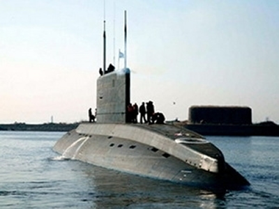
The source said, Admiralteyskie Verfi has built two 636 submarines, of which the first is scheduled for completion this summer and it will be tested and handed over this September. The second ship will be tested this May and will be checked and taken over this year end. Admiralteyskie Verfi will transfer the entire six 636 submarines to Vietnam before 2018 under a contract signed in 2009 within the framework of the visit to Russia by Prime Minister Nguyen Tan Dung. The contract also stipulates that Russia is obliged to train Vietnamese officers and sailors who operate 636 submarines, and provide technical equipment and spare parts required for this type of submarine.
China Plans Manned Submersible 2013 Missions.
The manned submersible 'Jiaolong' will conduct scientific trial missions between June and September 2013. The four months of missions, which will include research in the South China Sea and the northeast Pacific Ocean, mark the start of a five-year trial period for the Jiaolong before it starts regular operation, the China Ocean Mineral Resources Research & Development Association, an agency of China's State Oceanic Administration (SOA) informed Xinhua. The Jiaolong completed a record dive of 7,062 meters in the Pacific Ocean's Mariana Trench in June 2012, demonstrating that it has the ability to allow China to conduct deep-sea scientific research and resource exploration in 99.8 percent of the world's oceans. However, it appears that the Jiaolong is not yet ready for regular operation, as its mother ship has yet to be built and its oceanauts and maintenance team still need training.
Russian Navy develops mini submarines.
Russian shipbuilders are developing new "super mini" submarines, the United Shipbuilding Corporation (USC) state holding company said Friday. Work on the sea craft was in progress at the St. Petersburg-based Malakhit naval machine manufacturing bureau and that Navy command has been showing interest in the project, the company's vice president Igor Zakharov said. Alexander Terenov, an advisor to Malakhit's general director, said the Project 865 Piranha submersible (NATO reporting name Losos) could go beyond just "hit and run" operations. "They have a broad range of applications and can carry full-fledged missile and torpedo systems," Terenov said. He said the Piranha could also be deployed for the protection of naval installations, and would be operated by small crews and cost little to maintain. Piranha is a midget submarine designed for special operations and is almost completely silent. Only two Piranha-class submarines were reportedly ever built in Russia.
|
Underwater Vandals Damage Japanese Midget Submarine.
Vandals have damaged the wreck of a Japanese midget submarine in Sydney Harbour and made off with protected relics. The submarine, known as the M24, is a key piece of Australian World War II history and was one of three midget submarines that entered Sydney Harbour on May 31, 1942. It's believed divers entered the protected zone around the shipwreck and broke off and removed propeller blades and relics, reports The Sydney Morning Herald. One of the three submarines was blown up by its occupants after getting tangled in the boom net across the harbour. The M24 followed and fired torpedoes at the cruiser USS Chicago but instead hit the HMAS Kuttabul, killing 21 naval personnel. It then disappeared until 2006, when scuba divers discovered its wreck off a Sydney beach.
Russia’s fifth-generation submarines to feature stealth technology.
The distinguishing feature of Russia’s newest, fifth-generation submarines will be stealth rather than higher speed or greater depth capabilities, Vladimir Dorofeyev, head of the Malakhit Design Bureau, said.“It is quite possible that new technological solutions will appear to protect submarines from detection,” he said in an interview with RIA Novosti. The fifth-generation submarine will acquire new capabilities through close interaction with other components of the Armed Forces, including surface warships, warplanes, spacecraft, satellites, as well as other submarines, based on an integrated information space, he said. He added, however, that the incorporation of submarines, alongside surface warships and warplanes, into a single communications system is at odds with the idea of a “stealth vessel,” insofar as the sheer exchange of information is a “telltale sign.” “But that is a field that requires serious scientific-technical research,” Dorofeyev said Rubin Central Design Bureau head Igor Vilnit said on Monday work is in progress on fifth-generation nuclear-powered and diesel submarines. The new submarine will have a service life of about 50 years, he said. The fifth generation will be distinguished by its lowered noise, automated control systems, reactor safety, and long-range weapons.
B.C. company launches personal mini-submarines.
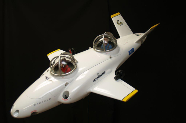
A North Vancouver business has made it possible for wannabe secret agents and marine biologists to explore the depths of coastal waters in their own personal luxury submarines. Each made-to-order “Spymaster OrcaSub” comes with a hefty $2-million price tag, but creators at Nuytco Research say there’s more of a demand than one might think. “When you consider that there are people out there with $20-million and $30-million yachts, it’s not that big a jump,” Nuytco Research founder Phil Nuytten said. The two-person mini subs are 22 feet long with business-class style seating and 360-degree viewing domes, a news release states. Operators can dive to 2,000 feet below sea level. They take six months to build at the company’s North Vancouver location. With a narrow fuselage and wing-mounted thrusters, the submarines look far more like airplanes. But one doesn’t need to be a pilot to figure out the controls. “We had George Lucas’s 12-year-old daughter in one of the subs,” Nuytten said. “We wanted to see how long it would take her to figure out the controls. It was like 20 minutes.” Nevertheless, the company provides buyers with a five-day training course before they’re released to roam deep, dark waters and underwater lairs.
Submarines – A Short History.
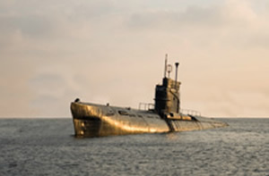
The adjective submarine means "under the sea" while the noun is a shortened form of submarine boat, a vessel capable of independent operation underwater. While the name usually signifies large, crewed vessels, it can also refer to smaller boats like midget submarines, remotely operated vessels or robots working under the sea. Today's submarines developed from early inventions like the Diving Bell and the Bathysphere.
Early Submarines.
With the human race's fascination for exploration, it soon became clear that divers were not able to survive at depths necessary to explore the oceans. The Diving Bell was one of the earliest inventions to facilitate underwater work and exploration. First described by Aristotle in the 4th century BC and used by Alexander the Great to explore the Mediterranean, it was not until 1535 that Guglielmo de Lorena designed and used what is considered the first modern diving bell. Consisting of a rigid chamber used to transport divers to great depths, there were two types, the wet bell and the closed bell. The wet bell was a chamber, open at the bottom, suspended by cables and housing a small number of divers. Water pressure kept the air trapped inside the bell. The divers could not move it, nor could it operate independently because of being tethered. The closed bell had two parts; a sealed unit which was the chamber where the divers lived and a bell which could be locked on and off the chamber and which transported the divers to their destination. Surprisingly we have to go back to 1620 to find the first moving submersible, although it was not capable of independent movement. Built by Dutchman, Cornelius Drebbel, working for James I of England and designed by mathematician William Bourne, its purpose was underwater exploration and it was propelled by oars. In 2002 a two-person copy of was built for the BBC's "Building the Impossible" and was rowed under water at Dorney Lake at Eton. It was not long before the military potential of submarines was recognised and in 1648 Bishop John Wilkins of Chester mentioned the submarine's strategic advantages in his "Mathematicall Magick". These included:-
- Ability to travel invisibly to any coast without discovery.
- Safety from tides, tempests, ice, pirates and robbers.
- A useful tool against naval enemies.
- A means of conveying supplies secretly to anywhere accessible by water.
- A vehicle for conducting underwater experiments.
The Bathysphere was a much later invention, designed in 1928 by the American Otis Barton for studying underwater wildlife. Setting several world records for the deepest dive by a human, it consisted of a hollow sphere with windows made of fused quartz and an entrance hatch which was bolted down before submersion. Oxygen was supplied from high pressure cylinders inside the vessel while CO2 and moisture were absorbed by pans of calcium chloride and soda lime inside the walls. Cables lowered and raised it and provided telephone communication between divers and surface. By the end of the 19th century subs had been adopted by several navies. They were widely used in World War I for attacking enemy surface vessels or other submarines, blockade running and reconnaissance. Civilian uses included marine science, salvage, exploration and inspection and maintenance. They also had specialised functions like search-and-rescue, undersea cable repair and archaeology.
Submarine Design.
Traditionally submarines were cylindrical in shape, with conical or hemispherical ends. Their "working" section was a vertical structure, usually in the middle of the vessel, which housed the communications and sensing devices and the periscopes. Americans call this the "sail" while in Europe it is known as the "fin". In early vessels there was a separate pressure hull above the main body, called the "conning tower", from which short periscopes could be used. The first simple fixed periscope using mirrors was built in 1854 but was superseded by a prismatic version in 1861, after which they were regularly used in submarines. The propeller was located at the rear, along with hydrodynamic control fins and ballast tanks. Some of the specialised smaller submarines varied significantly from this design. The wide variety of submarine types ranges from one or two-person vessels that can stay under water for a few hours, to larger versions capable of submersion for as long as six months at a time.
Some Notable Submarines.
- The Turtle.
This was the first military submarine and the earliest one capable of independent underwater operation. Built in America in 1775, it held one person and used screws for propulsion. It was designed for use against the British Royal Navy as a means of attaching explosive charges to ships in harbour. - The Alligator.
This was the first U.S. Navy submarine, launched in 1862 and was the first submarine to use compressed air and an air filtration system. Although initially propelled by hand powered paddles, it was soon converted to a screw propeller powered by a hand crank. It was the largest American Civil War submarine, measuring 14 metres by 1 metre. - The Plongeur.
This was the first submarine not relying on human propulsion. It was launched by the French in 1863 and used a compressed-air engine. Air was stored in 23 tanks taking up a huge amount of space and resulting in the vessel measuring a massive 43 metres in length. It was armed with a torpedo and a ram to break holes in enemy ships. - Ictineo II.
Designed in 1864 in Spain, it was the first submarine powered by an air independent engine, measured 14 metres, held a crew of two and could remain submerged for two hours. The double-hulled vessel solved many of the pressure and buoyancy control problems which had bothered earlier subs. - Nautilus.
In 1870 the fictitious Nautilus, which figured in Jules Verne's 20,000 Leagues under the Sea, was more advanced than any real submarine and inspired inventors worldwide to improve on the current designs. - Fenian Ram and Holland VI.
Launched in 1881, Fenian Ram was the first submarine designed by the Irish inventor John Philip Holland, using internal combustion engines on the surface and electric battery power when submerged. Its successor Holland VI was launched in 1897 and purchased by the United States Navy; their first commissioned submarine. Holland submarines were the first mechanically powered subs to be put into service by the navies of Great Britain, Japan Russia and the U.S. - U-boats.
World War I saw submarines making a significant impact. German U-boats were responsible for sinking Britain's Lusitania, which was one of the reasons for the U.S. entering into the war. Their tactics were to operate primarily on the surface using their regular engines, then submerging to attack using battery power. In cross-section they were triangular with a keel to minimise rolling when on the surface. During the war U-boats were responsible for sinking more than 5,000 Allied ships. - Submarine Aircraft Carriers.
These were developed between the two world wars and equipped with waterproof hangar and steam catapult to launch and recover small seaplanes. They acted as a reconnaissance unit ahead of the fleet in the days before radar. By World War II Germany had the largest submarine fleet and used it with devastating effect, but with technical advances like radar and sonar the Allies were able to detect their positions, attack them and route their convoys around them. - The Russian Typhoon Class.
Named "Akula" meaning "Shark" by the Russians and "Typhoon" by NATO, these were the biggest ever built measuring 175 metres in length and 23 metres in width. They were nuclear-powered ballistic missile submarines used by the Soviet Navy in the 1980s and were quieter and more manoeuvrable than their forerunners. They had six torpedo tubes for launching a variety of torpedoes, missiles and mines. They could stay submerged for at least 120 days and incorporated civilised living conditions for their crews. They featured multiple pressure hulls which made them much wider than traditional subs. Two pressure hulls were positioned parallel with each other with a third above them and two more for the torpedoes and steering gear. This made them much safer than the older types of vessel, as even if one of the hulls was breached, the crew could remain safe and there was far less risk of flooding. They patrolled under the Arctic ice cap from where they could surface to launch their missiles, safe from enemy subs and anti-submarine forces. They reached the end of their service in 2012 when the Russians decided that modernising them would be too expensive. - The Borei Class.
These 4th generation nuclear-powered missile submarines were introduced to replace the Typhoon. They have a more compact and hydrodynamically efficient hull and use pump-jet propulsion for the first time. They are smaller than the Typhoon at 170 metres long and 13 metres wide, with a submerged speed of about 46 kilometres per hour and can carry 16 missiles.
Submarines just one of drug trafficking latest innovations.
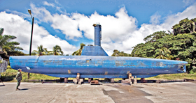
Colombia—Stacked along one edge of the Bahia Malaga naval base is what authorities call “the museum”—a long row of impounded vehicles that chart the evolution of the drug-trafficking industry. There are the lumbering fishing boats that used to run marijuana in the 1970s and 1980s, Miami Vice-era “go-fast” boats, and an entire fleet of manned and unmanned semi-submersibles. But the crown jewel of the display, and the stuff of drug-enforcement nightmares, is a fully functional narco-sub. Built in the jungle, the hulking blue submarine can carry 8 tons of cocaine and is similar to the nation’s own tactical sub, with one addition: This one has indoor plumbing. Discovered last year in the dense mangroves that make this region a smugglers’ paradise, the submarine—technically a “snorkel sub”—can hit speeds of 12 to 15 knots and travel 8,000 miles. That’s more than enough to make it to the coast of California and back, said Capt. Nelson Hernandez. Designed to travel 32 feet below water with only a small intake valve protruding, it would have been virtually undetectable if it were launched, he said. “With this kind of technology we might see a huge flow of drugs, or guns or anything heading north,” Hernandez said. As the United States wages the war on drugs, this stretch of Colombia’s Pacific coast is the Silicon Valley of narco-innovation. When the trafficking industry develops new maritime technology to stay ahead of the law, this is often where it appears first. For years, smugglers have been using semi-submersibles, which glide just below the water’s surface leaving no wake and a weak radar signature. Authorities began busting them in the late 1990s, but a local port manager in nearby Buenaventura recalls seeing the first one in the 1980s. But full-fledged submarines are relatively new. Only three have been found in South America in recent years—two in Colombia and one in neighboring Ecuador. A fourth, much earlier, version was discovered in Colombia’s capital in 2000. In Senate testimony last year, the US Drug Enforcement Agency’s (DEA) Chief of Intelligence Rodney Benson said the advent of “self-propelled fully submersible vessels...underscores the incredible lengths drug traffickers will take to move their product.” About 60 percent of Colombia’s submersible busts relied on intelligence sources and investigative work—not technology like radar, Hernandez said. Authorities have impounded 23 semisubmersibles and detected 96 over the years. Countless others have been scuttled by traffickers to keep from being caught, Hernandez said. For the vessels that make it away from the Colombian shores, an intelligence center in Key West, run by the US Southern Command, guides Coast Guard and DEA agents to suspect boats in collaboration with Central American law enforcement. While the submarine may be the most dramatic innovation, it’s not the only one. Tucked between the vessels at the “museum” are what look like steel torpedoes—or what officials here call “unmanned submersibles.” The torpedoes are streamlined containers that can carry several tons of cocaine and be towed behind an inconspicuous fishing vessel or attached to the hull of a boat. If the traffickers suspect they are about to be raided, they simply cut it loose. “About a month ago, we noticed that they were starting to use electronic beacons on the unmanned submersibles,” Hernandez said. The technology allows smugglers to ditch their cargo and recover it days or weeks later. Capt. Ricardo Benitorevollo is a submariner in the Colombian Navy and has studied the narco-sub carefully. He said the machine has sophisticated submersion and trim controls, a ballast management system and central AC. When they discovered it, it was loaded with packages of caustic soda, suggesting the machine also was going to have an oxygen scrubber. He estimated it might cost $2 million to build. Asked how it compared to Colombian subs, he said it was very similar to the Navy’s tactical sub but had more amenities. On the Colombian sub, officers have to go on deck to use the bathroom. The narco-sub has an interior bathroom. There’s also another difference, he said: “Their beds are bigger.”
Iran is producing explosive mini-submarines.
Iranian production lines are turning out a new type of speed mini-submarine customized for combat against the US and other Western navies present in Persian Gulf waters. On the principle of asymmetric warfare, the new pint-sized Iranian submarines are light in weight and able to dart nimbly around large vessels to explode on contact with their floating target. Their pilots are bent on suicide. These mini-subs are designed to complement the 2,000 Revolutionary Guards’ explosive speedboats.
China Buying Russian Submarines.
State arms exporter Rosoboronexport has signed a framework agreement with China on the joint development and construction of four non-nuclear Amur-1650 conventional submarines for the Chinese Navy, a news report said Thursday. The final contract is tentatively worth $2 billion and is expected to be signed by the parties no earlier than 2015, Kommersant reported. The agreement stipulates for two of the submarines to be built in Russia and two in China, with special provisions in place in the contract to ensure that no intellectual property is copied from the Russian side, a source close to Rosoboronexport told the business daily. An additional agreement for the first stage of work could be signed by the end of the year, he said, adding that a Russian contractor had not yet been selected for construction of the submarines. China may become the first buyer of the Amur-1650 submarines, beating out India and Venezuela, both of which previously expressed interest, Kommersant said. Another source close to the arms exporter said the submarine contract "is very important for Russia and tops the presidential list of projects with China."
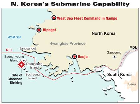
North Korean submarines have posed and will pose a grave threat to the security of South Korea both in the peacetime and wartime,'' the researcher said. "As it has done in the past, the North is expected to continue to use the western waters as a major flashpoint for conflicts with the South." The North Korean Navy consists of two fleet headquarters in the East and West Sea, 13 squadrons, and two maritime sniper brigades under the Naval Command. The North's Navy is believed to operate about 650 vessels, including 70 submarines -- 1,800-ton Romeo-class, 370-ton Sang-O (Shark)-class, 90-ton Yugo-class and midget submarines with a weight of five to 10 tons -- which are capable of placing mines and attacking South Korean vessels. About 60 percent of the vessels are deployed in forward naval bases.
Who's to Blame?
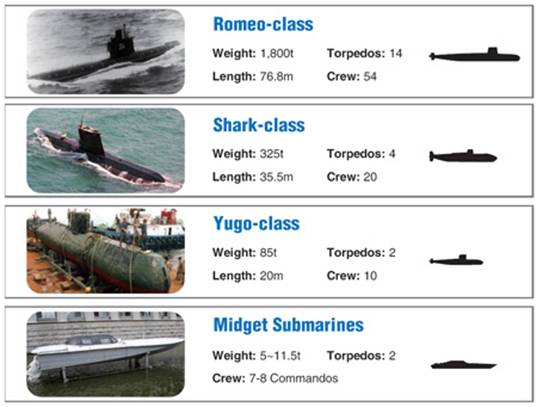
The Romeo class consists of Soviet diesel-electric submarines built in the 1950s. The North's Navy is believed to operate Romeo-class submarines that are both locally assembled with Chinese parts and directly imported from China. The 76-meter-long sub can sail at 15.2 knots surfaced and 13 knots submerged. It can carry 21 anti-ship/anti-submarine torpedoes or 28 mines. Defence Minister Kim Tae-young said earlier that he didn't believe the Romeo-class sub was the culprit of the March 26 ship sinking, citing the ship's slow speed and the shallow water in the West Sea. Most experts have suspected that Sang-O class subs could be blamed for the incident that has left 38 South Korean crewmen dead and eight others missing. The 34-meter long, 3.8-meter wide Sang-O class is equipped with four Russian 53-65KE (533mm) torpedoes and is also capable of mine-laying. The sub with a crew capacity of five to 10 is known to be mainly used by special forces in infiltrating areas or laying mines. It is believed to be capable of conducting underwater operations for up to 20 days without refueling. The sub has a speed of 8.8 knots. North Korea's Navy is believed to have built 17 to 22 Sang-O class submarines in the 1990s. A Sang-O class sub was found stranded off the waters of Gangneung in the eastern Gangwon Province in 1996. Rep. Kim Hak-song, chairman of the National Assembly's Defence Committee, claimed earlier this month that South Korean intelligence had detected that Sang-O class submarines were active around the time when the Cheonan sank on the night of March 26 after an unexplained explosion.
Kim revealed that Sang-O class submarines stationed at a naval base in Bipagot, just north of the Northern Limit Line (NLL), had maneuvered between March 23 and 27, and one of the subs had disappeared from surveillance systems.
The 20-meter-long Yugo class is comprised of four midget submarines used primarily for infiltration and espionage by North Korea. The class is so named because it was built from plans supplied to North Korea by Yugoslavia in 1965. It has a submerged displacement of 90 tons and has a speed of 10 knots surfaced and 4 knots submerged. The sub has a capacity of four to six people and two 406 mm torpedoes. A Yugo submarine was detected and captured off the waters of Ganghwa Island on Nov. 20, 1998, while it was attempting to infiltrate spies, who subsequently escaped back to the North. North Korea is believed to have 30 Yugo class submarines. South Korean authorities say the possibility of a semi-submersible's involvement in the Cheonan sinking remains low given the high seas and waves in the West Sea. A mini-submarine does not have the capability to carry torpedoes that could have destroyed the 1,200-ton Cheonan, they say. North Korea has 5 to 11 five-ton mini-submarines armed with two 320mm torpedoes. They can carry seven to eight people.
New Russian SSBN Submarine Enters Service.
January 15, 2013: A year ago Russia announced that its SSBNs (nuclear powered ballistic missile boats) would resume long range "combat patrols" within a year. On schedule the Russian Navy finally accepted its first new Borei class SSBN (Yury Dolgoruky) for service last December 30th. Thus it appears that the newly commissioned Yury Dolgoruky will be the first Russian SSBN in many years to make a long range cruise. The Russians will probably not announce this until it’s all over, lest something go wrong at sea. A second Borei is undergoing sea trials and is expected to enter service next year. A third Borei class boat is just beginning sea trials this month. In recent years, there have been only about ten nuclear submarine patrols a year, each lasting three months at most and usually a lot less. Most have not gone far from Russian waters and some were by recently built SSNs (nuclear attack subs) or SSGNs (SSNs equipped with cruise missiles) and not by SSBNs. The problem here was that the Russian Navy has not only shrunk since the end of the Cold War in 1991 but it has also become much less active. Much of the time at sea consisted of short range training missions, which often lasted a few days, or just a few hours. But the true measure of a fleet is the "combat patrol" or "deployment." In the U.S. Navy most of these last from 2-6 months and in the last decade U.S. nuclear subs have carried out ten times as many patrols as their Russian counterparts. Currently, Russia only has 15 SSBN (nuclear ballistic missile sub) boats in service and not all of them have a full load of missiles. Some lack full crews or have key systems in need of repair. Twelve of the SSBNs are Delta IVs, which are overdue for retirement and rarely go to sea. Russia has only 15 modern, 7,000 ton, Akula SSNs (nuclear attack subs) in service. Actually, three are in reserve, for lack of money![]() and crews, and another has been leased to India. The Akulas began building in the late 1980s and are roughly comparable to the American Los Angeles class. All of the earlier Russian SSNs are trash and most have been decommissioned. There are also seven SSGN (nuclear subs carrying cruise missiles) and 20 diesel electric boats. There is a new class of SSGNs under construction but progress, and promised funding increases, have been slow. Currently, the U.S. has nine of the new, 7,700 ton, Virginia class SSNs in service, five under construction and 19 more planned. The mainstay of the American submarine force is still the 6,100 ton Los Angeles-class SSN. Sixty-two of these submarines were built, 42 of which remain in front-line service, making it probably the largest class of nuclear submarines that will ever be built. The Seawolf-class of nuclear attack submarines stopped at three from a planned class of twenty-nine. The 8,600 ton Seawolf was designed as a super-submarine, designed to fight the Soviet Navy at its height. Reportedly, it is quieter going 40 kilometers an hour than the Los Angeles-class submarines are at pier side. The peak year for Russian nuclear sub patrols was 1984, when there were 230. That number rapidly declined until, in 2002, there were none. Since the late 1990s, the Russian navy has been hustling to try and reverse this decline. But the navy budget, despite recent increases, is not large enough to build new ships to replace the current Cold War era fleet that is falling apart. Since the end of the Cold War in 1991, most of the ship building money has gone into new nuclear subs. Six Akulas have been completed in that time, but the first two of a new generation of SSBNs, the Borei class was delayed by technical problems, a new ballistic missile that wouldn't work, and lack of money. The first three Borei class boats, after many delays, are finally ready for service and ended up costing over two billion dollars each. The ballistic missile for the Borei was just approved last year and there won't be enough of them to fill all the Borei silos for a year or more. The Russian admirals made their big mistake in the early 1990s, when the dismantling of the Soviet Union left the second largest fleet in the world with only a fraction of its Cold War budget. Rather than immediately retire ninety percent of those ships, Russia tried to keep many of them operational. This consumed most of the navy budget and didn't work. There were too many ships, not enough sailors and not enough money for maintenance or training at sea. The mighty Soviet fleet was quickly turned into scrap or rusting hulks tied up at crumbling out-of-the way naval bases. While Western nuclear subs can last for about thirty years Russian models rarely get past twenty. That means two new SSN or SSGN have to be put into service each year to maintain a force of forty boats. Unless the sub construction budget get billions more dollars a year, that is not going to happen. Right now, the priority is on producing a new class of SSBNs (five more Boreis are planned or under construction). These Boreis are essential because they carry SLBM (Sea Launched Ballistic Missiles) that provide a critical (they are much harder to destroy in a first strike than land based missiles) portion of the nuclear deterrent. The rest of the Russian armed forces, like most of the navy, is in sad shape and unable to resist a major invasion. Only the ICBMs and SLBMs guarantee the safety of the state. So the way things are going now, in a decade or two, Russia will end up with a force consisting of a dozen SSNs and a dozen SSBNs. The current fleet of nuclear subs is tiny and the Russians would rather keep them tied up at dock most of the time. The crews can do a lot of training at dockside, and only go to sea a few times a year to check on their state of training. Given the number of accidents their subs have had in the past decade, the training the crews are getting now is not sufficient.
and crews, and another has been leased to India. The Akulas began building in the late 1980s and are roughly comparable to the American Los Angeles class. All of the earlier Russian SSNs are trash and most have been decommissioned. There are also seven SSGN (nuclear subs carrying cruise missiles) and 20 diesel electric boats. There is a new class of SSGNs under construction but progress, and promised funding increases, have been slow. Currently, the U.S. has nine of the new, 7,700 ton, Virginia class SSNs in service, five under construction and 19 more planned. The mainstay of the American submarine force is still the 6,100 ton Los Angeles-class SSN. Sixty-two of these submarines were built, 42 of which remain in front-line service, making it probably the largest class of nuclear submarines that will ever be built. The Seawolf-class of nuclear attack submarines stopped at three from a planned class of twenty-nine. The 8,600 ton Seawolf was designed as a super-submarine, designed to fight the Soviet Navy at its height. Reportedly, it is quieter going 40 kilometers an hour than the Los Angeles-class submarines are at pier side. The peak year for Russian nuclear sub patrols was 1984, when there were 230. That number rapidly declined until, in 2002, there were none. Since the late 1990s, the Russian navy has been hustling to try and reverse this decline. But the navy budget, despite recent increases, is not large enough to build new ships to replace the current Cold War era fleet that is falling apart. Since the end of the Cold War in 1991, most of the ship building money has gone into new nuclear subs. Six Akulas have been completed in that time, but the first two of a new generation of SSBNs, the Borei class was delayed by technical problems, a new ballistic missile that wouldn't work, and lack of money. The first three Borei class boats, after many delays, are finally ready for service and ended up costing over two billion dollars each. The ballistic missile for the Borei was just approved last year and there won't be enough of them to fill all the Borei silos for a year or more. The Russian admirals made their big mistake in the early 1990s, when the dismantling of the Soviet Union left the second largest fleet in the world with only a fraction of its Cold War budget. Rather than immediately retire ninety percent of those ships, Russia tried to keep many of them operational. This consumed most of the navy budget and didn't work. There were too many ships, not enough sailors and not enough money for maintenance or training at sea. The mighty Soviet fleet was quickly turned into scrap or rusting hulks tied up at crumbling out-of-the way naval bases. While Western nuclear subs can last for about thirty years Russian models rarely get past twenty. That means two new SSN or SSGN have to be put into service each year to maintain a force of forty boats. Unless the sub construction budget get billions more dollars a year, that is not going to happen. Right now, the priority is on producing a new class of SSBNs (five more Boreis are planned or under construction). These Boreis are essential because they carry SLBM (Sea Launched Ballistic Missiles) that provide a critical (they are much harder to destroy in a first strike than land based missiles) portion of the nuclear deterrent. The rest of the Russian armed forces, like most of the navy, is in sad shape and unable to resist a major invasion. Only the ICBMs and SLBMs guarantee the safety of the state. So the way things are going now, in a decade or two, Russia will end up with a force consisting of a dozen SSNs and a dozen SSBNs. The current fleet of nuclear subs is tiny and the Russians would rather keep them tied up at dock most of the time. The crews can do a lot of training at dockside, and only go to sea a few times a year to check on their state of training. Given the number of accidents their subs have had in the past decade, the training the crews are getting now is not sufficient.
Deep-sea Submersible Purchase by OceanGate.
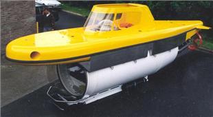
Deep-sea Submersible 'Lula'.
OceanGate Inc. provider of deep-sea manned submersible solutions, buys 3-person, diesel-electric submersible 'Lula'f rom Portugal's Rebikoff-Niggeler Foundation. The submarine, which can operate at a depth of 500 meters (1,640 feet), was purchased to meet the increased demand for manned submersibles in commercial applications focused on biological and environmental surveys, monitoring, and inspection. Having conducted hundreds of dives during her 10-year operating history, Lula will expand OceanGate's ability to meet growing industry client demands, helping fulfill contracts for the University of Washington on behalf of the Defense Advanced Research Projects Agency (DARPA) and Office of Naval Research. Lula will also supplement OceanGate's Antipodes submersible in performing survey, inspection, and monitoring work in the Gulf of Mexico. The submersible is equipped with a five-function manipulator and accompanying sampling box, which together allow for in-situ sampling of marine objects, core sampling for geologic research, and collection of diverse data sets. As a direct observation platform, Lula offers excellent visibility and outstanding opportunity for clients doing monitoring and inspection work. Her 1.5-meter diameter hemispherical viewing dome delivers a wide field of view. In addition, Lula is outfitted with state-of-the-art illumination systems, video and photo equipment, and pre-installed oceanographic data sensors. Lula's diesel-electric power system permits direct sailing to dive sites, thereby requiring minimum surface support, and enables efficient international mobility, furthering OceanGate's global reach. Her ease of mobility translates to significant cost savings, as large crews and surface support vessels are not required. "Lula's power system provides long range capabilities which help extend our expeditions, and her depth rating of 500 meters will be valuable in a multitude of commercial applications," states Stockton Rush, co-founder and CEO of OceanGate. "She fits well into our commitment to cost-effective, manned submersible alternatives for commercial clients, and will help us to rapidly expand our exploration activities around the globe."
Too Many Sub Targets.
On January 8th the Colombian Navy captured its first drug smuggling submersible vessel of the year. This one was 18 meters (56 feet) long and capable of carrying over four tons of cocaine. It had been abandoned at sea and was towed back by a Colombian Navy ship to try and find out what happened. Last year the Colombians captured eight of these. Naval forces from the United States and other nations along the Pacific coast and the Caribbean caught even more. But the detection system, run mainly by the United States, locates a lot more of these cocaine subs than there are warships available to run them all down. For two decades the United States has used a special interagency (Departments of Homeland Security, Justice, State, and Defense) and international (over a dozen nations participate) intelligence sharing/analysis operation (Joint Interagency Task Force-South) to track drug smuggling from South America. For the last decade the task force has become quite expert at tracking the submarines and submersibles built in South America for smuggling cocaine to North America and, recently, all the way to Europe. Some of these long range subs are apparently going all the way from Ecuador to the United States, bypassing the Mexican cartels (who have been fighting each other, in a big way, for the last five years). Particularly worrisome are the larger boats headed for Europe. Little is known about these, expect that they exist. These subs would be more at risk of being lost because of accident or bad weather than being spotted. European navies (especially Portugal and Spain) and coast guards have been alerted and are looking. Despite losing over a hundred of these vessels to the U.S. and South American naval forces (and dozens more to accidents and bad weather), the drug gangs have apparently concluded that the subs are the cheapest and most reliable way to ship the drugs. It's currently estimated that over 80 percent of the cocaine smuggled into the United States leaves South America via these submarines or semi-submersible boats. Most of these craft are still "semi-submersible" type vessels. These are 10-20 meter (31-62 foot) fiberglass boats, powered by a diesel engine, with a very low freeboard and a small "conning tower", providing the crew (of 4-5), and engine, with fresh air and permitting the crew to navigate. A boat of this type was, since they first appeared in the early 1990s, thought to be the only practical kind of submarine for drug smuggling. But in the last decade the drug gangs have developed real submarines, capable of carrying 5-10 tons of cocaine that cost a lot more and don't require a highly trained crew. These subs borrow a lot of technology and ideas from the growing number of recreational submarines being built. The Colombian security forces and other Latin American navies have been responsible for most of these vessel captures. Usually these boats are sunk by their crews when spotted but the few that were captured intact revealed features like an extensive collection of communications gear, indicating an effort to avoid capture by monitoring many police and military frequencies. The Colombians have captured several of these vessels before they could be launched. In the last few years the Colombians have been collecting a lot of information on those who actually build these subs for the drug gangs and FARC (leftist rebels that provide security and often transportation for moving cocaine). That includes finding out where the construction takes place. Colombian police have arrested dozens of members of gangs that specialized in building submarines and semisubmersible boats. As police suspected, some of those arrested were retired or on active duty with the Colombian Navy (which operates two 1970s era German built Type 209 submarines). These arrests were part of an intense effort to find the people responsible for building subs for cocaine gangs. Find the builders and you stop the building efforts. In this case it has only delayed some construction and made it more expensive to build these boats. Ecuadoran police found the first real diesel-electric cocaine carrying submarine three years ago. It was nearly completed and ready to go into a nearby river, near the Colombian border, and move out into the Pacific Ocean. The 23.5 meter (73 foot) long, three meter (nine feet) in diameter, boat was capable of submerging. The locally built boat had a periscope, conning tower, and was air conditioned. It had commercial fish sonar mounted up front so that it could navigate safely while underwater. There was a toilet on board but no galley (kitchen) or bunks. Submarine experts believed that a five man crew could work shifts to take care of navigation and steering the boat. The boat could submerge to about 16 meters (50 feet). At that depth the batteries and oxygen on board allowed the sub to travel up 38 kilometers in one hour or at a speed of 9 kilometers an hour for 5-6 hours. This would be sufficient to escape any coastal patrol boats that spotted the sub while it moved along on the surface (its normal travel mode). The boat could also submerge to avoid very bad weather. The sub carried sufficient diesel fuel to make a trip from Ecuador to Mexico. There was a cargo space that could hold up to seven tons of cocaine. The sub was captured where it was being assembled and a nearby camp for the builders appeared to house about fifty people. A lot of evidence was collected, and apparently the U.S. DEA (Drug Enforcement Agency) used that to develop clues about who was involved. It was the DEA that put together the pieces that led to identifying key people. The Ecuadoran boat was the first such sub to be completed but not the first to be attempted. Back in the 1990s, Russian naval architects and engineers were discovered among those designing and building a similar, but larger, boat. However, that effort did not last, as the Russian designs were too complex and expensive. It was found easier to build semi-submersible craft. But more and more of these new type subs are being found.
Chinese PLA Submarine Database. created by Sid Trevethan |
|||||||||||
Class Name |
Type |
Total in Service for Spring of Year |
Fleet Assignment |
||||||||
|
|
2004 |
2005 |
2006 |
2007 |
2008 |
2009 |
2010 |
North |
East |
South |
Type 094 |
SSBN |
0 |
0 |
0 |
1 |
1 |
1 |
2 |
0 |
0 |
0 |
Type 093 |
SSGN |
1 |
1 |
2 |
2 |
3 |
3 |
4 |
1 |
0 |
0 |
Xia 092 |
SSBN |
1 |
1 |
1 |
1 |
1 |
1 |
1 |
1 |
0 |
0 |
Han 091 |
SSN |
5 |
5 |
5 |
5 |
5 |
5 |
5 |
5 |
0 |
0 |
Kilo III (AIP) |
SS |
0 |
0 |
0 |
0 |
0 |
3 |
6 |
0 |
0 |
0 |
Kilo II (636) |
SS |
2 |
2 |
6 |
10 |
10 |
10 |
10 |
0 |
2 |
0 |
Kilo I (877) |
SS |
2 |
2 |
2 |
2 |
2 |
2 |
2 |
0 |
2 |
0 |
Song II (039G) |
SSG |
6 |
7 |
7 |
9 |
9 |
11 |
11 |
0 |
4 |
2 |
Song I (039) |
SSG |
1 |
1 |
1 |
1 |
1 |
1 |
1 |
0 |
1 |
0 |
Ming III (035AIP) |
SS |
6 |
6 |
6 |
6 |
6 |
6 |
6 |
0 |
0 |
6 |
Ming II (035E) |
SS |
12 |
12 |
12 |
12 |
12 |
12 |
12 |
12 |
0 |
0 |
Ming I (035) |
SS |
[2] |
0 |
0 |
0 |
0 |
0 |
0 |
0 |
0 |
0 |
Romeo II (033G) |
SSG |
[1] |
0 |
0 |
0 |
0 |
0 |
0 |
0 |
0 |
0 |
Romeo I (033) |
SS |
21 |
18 |
12 |
6 |
6 |
6 |
6 |
7 |
7 |
7 |
Reserve Romeo |
SS |
15 |
15 |
15 |
15 |
12 |
9 |
6 |
5 |
5 |
5 |
Moth. Romeo |
SS |
[12] |
[12] |
[12] |
[12] |
[12] |
[12] |
[12] |
0 |
0 |
[12] |
Gulf (Auxiliary) |
SSBA |
[1] |
[1] |
[1] |
[1] |
[1] |
[1] |
0 |
[1] |
0 |
0 |
Sang-O (Xpt) |
SSM |
1 |
1 |
1 |
1 |
1 |
1 |
1 |
0 |
0 |
1 |
SSN Total |
SSN |
7 |
7 |
8 |
9 |
10 |
10 |
12 |
7 |
0 |
0 |
SS Total |
SS |
66 |
64 |
62 |
62 |
59 |
58 |
55 |
24 |
21 |
21 |
Sub Total |
Subs |
73 |
71 |
70 |
71 |
69 |
68 |
67 |
31 |
21 |
21 |
Class Name |
Type |
Submerge |
Surface |
Sonar CM |
Sonar |
Noise |
Battery |
Weap. |
Torpedo |
Torpedo |
|
|
Speed |
Speed |
Level |
Level |
|
Points |
Rounds |
Tubes 1 |
Rating |
Type 094 |
SSBN |
27 |
18 |
4 |
6 |
Very Quiet |
12 |
20 |
6 0 |
20 |
Type 093 |
SSGN |
30 |
18 |
4 |
6 |
Very Quiet |
12 |
20 |
6 0 |
20 |
Xia 092 |
SSBN |
22 |
12 |
3 |
5 |
Average |
9 |
20 |
6 0 |
20 |
Han 091 |
SSN |
26 |
12 |
2 |
5 |
Average |
9 |
20 |
6 0 |
20 |
Kilo III (AIP) |
SS |
17 |
12 |
4 |
6 |
Very Quiet |
120 |
18 |
6 0 |
20 |
Kilo II (636) |
SS |
17 |
12 |
4 |
6 |
Very Quiet |
24 |
18 |
6 0 |
20 |
Kilo I (877) |
SS |
17 |
12 |
3 |
5 |
Quiet |
24 |
18 |
6 0 |
20 |
Song II (039G) |
SSG |
22 |
15 |
4 |
6 |
Very Quiet |
180 |
12 |
6 0 |
20 |
Song I (039) |
SSG |
22 |
15 |
4 |
5 |
Quiet |
36 |
12 |
6 0 |
20 |
Ming III (035AIP) |
SS |
18 |
15 |
4 |
6 |
Very Quiet |
120 |
18 |
6 2 |
20 |
Ming II (035E) |
SS |
18 |
15 |
3 |
5 |
Quiet |
24 |
16 |
6 2 |
11 |
Ming I (035) |
SS |
18 |
15 |
2 |
4 |
Quiet |
24 |
12 |
6 2 |
11 |
Romeo II (033G) |
SSG |
12 |
15 |
2 |
4 |
Quiet |
39 |
14 |
6 2 |
11 |
Romeo I (033) |
SS |
12 |
15 |
3 |
5 |
Quiet |
39 |
14 |
6 2 |
11 |
Reserve Romeo |
SS |
12 |
15 |
2 |
4 |
Quiet |
39 |
14 |
6 2 |
11 |
Moth. Romeo |
SS |
12 |
15 |
2 |
3 |
Quiet |
39 |
14 |
6 2 |
11 |
Gulf (Auxiliary) |
SSBA |
15 |
15 |
2 |
3 |
Average |
14 |
265 |
6 4 |
11 |
Sang-O (Xpt) |
SSM |
8 |
8 |
2 |
4 |
Very Quiet |
4 |
0 |
0 |
0 |
Class Name |
Type |
LAB/CM |
LAB/CM |
LACM Name |
LAB/CM |
ASCM |
ASCM |
ASCM |
Weapons |
Mines7 |
|
|
Rating |
Range |
LABM Name |
Rounds |
Name |
Rating |
Range |
Notes |
|
Type 094 |
SSBN |
188 |
8,000 |
JL-2 |
16 |
HN-3 |
7 |
2,500 |
36 |
|
Type 093 |
SSGN |
na |
na |
na |
TTL |
HN-3 |
7 |
2,500 |
36 |
|
Xia 092 |
SSBN |
125 |
3,600 |
JL-1A |
12 |
na |
na |
na |
36 |
|
Han 091 |
SSN |
na |
na |
na |
TTL |
YJ-8 |
5 |
42 |
36 |
|
Kilo III (AIP) |
SS |
na |
na |
na |
na |
na |
na |
na |
|
36 |
Kilo II (636) |
SS |
na |
na |
na |
na |
na |
na |
na |
|
24 |
Kilo I (877) |
SS |
na |
na |
na |
na |
na |
na |
na |
|
24 |
Song II (039G) |
SSG |
na |
na |
na |
TTL |
YJ-8 |
5 |
42 |
24 |
|
Song I (039) |
SSG |
na |
na |
na |
TTL |
YJ-8 |
5 |
42 |
24 |
|
Ming III (035AIP) |
SS |
na |
na |
na |
na |
na |
na |
na |
|
326 |
Ming II (035E) |
SS |
na |
na |
na |
na |
na |
na |
na |
|
326 |
Ming I (035) |
SS |
na |
na |
na |
na |
na |
na |
na |
|
24 |
Romeo II (033G) |
SSG |
na |
na |
na |
6 |
YJ-1 |
5 |
42 |
28 |
|
Romeo I (033) |
SS |
na |
na |
na |
na |
na |
na |
na |
|
28 |
Reserve Romeo |
SS |
na |
na |
na |
na |
na |
na |
na |
|
28 |
Moth. Romeo |
SS |
na |
na |
na |
na |
na |
na |
na |
|
28 |
Gulf (Auxiliary) |
SSBA |
na |
na |
na |
na |
na |
na |
na |
|
44 |
Sang-O (Xpt) |
SSM |
na |
na |
na |
na |
na |
na |
na |
|
8 |
Class Name 9 |
Type |
Hull Numbers |
SOF |
Power8 |
|
|
|
Teams |
|
Type 094 |
SSBN |
409, 412 |
2 |
NS |
Type 093 |
SSGN |
407, 408, 410, 411, 413, 414 |
2 |
NS |
Xia 092 |
SSBN |
406 |
2 |
NS |
Han 091 |
SSN |
401, 402, 403, 404, 405 |
2 |
NS |
Kilo III (AIP) |
SS |
381, 382, 383, 384, 385, 386 |
1 |
DES |
Kilo II (636) |
SS |
366, 367, 368, 369, 370, 371, 372, 373, 374, 375 |
1 |
DES |
Kilo I (877) |
SS |
364, 365 |
1 |
DES |
Song II (039G) |
SSG |
321, 322, 323, 324, 314, 315, 316, 317, 318, 319, 325 |
1 |
DES |
Song I (039) |
SSG |
320 |
1 |
DES |
Ming III (035AIP) |
SS |
361, 305, 306, 307, 308, 309 |
1 |
DES |
Ming II (035E) |
SS |
342, 352, 353, 354, 355, 356, 357, 358, 359, 360, 362, 363 |
1 |
DES |
Ming I (035) |
SS |
, 233 |
1 |
DES |
Romeo II (033G) |
SSG |
351 |
1 |
DES |
Romeo I (033) |
SS |
293, 294, 295, 296, 297, 298, 299, 300, 301, 302, 303, 304, 343 to 349, 355 |
1 |
DES |
Reserve Romeo |
SS |
268, 269, 270, 271, 272, 275, 276, 277, 278, 279, 280, 286, 287, 291, 292 |
1 |
DES |
Moth. Romeo |
SS |
249, 250, 251, 252, 253, 254, 255, 256, 257, 258, 259, 260 |
1 |
DES |
Gulf (Auxiliary) |
SSBA |
200 |
1 |
DES |
Sang-O (Xpt) |
SSM |
351 Hull number duplicates Romeo II. |
1 |
DES |
Notes |
Note 1: Forward tubes listed to left, aft tubes listed to right. |
Note 2: TTL= Torpedo Tube Launch = missile shots replace mine shots. |
Note 3: Not operational with nuclear warheads. |
Note 4: May only launch when surfaced. |
Note 5: Gulf normally only loads 12 torpedoes. |
Note 6: Ming normally only loads 28 mines. |
Note 7: Subs carry mines/cruise missiles or torpedos. Reduce torpedo shots by 1 for every two mines carried, disregard at zero torpedo shots. Exception 1: Sang-o only carries mines. |
Note 8: NS = Nuclear Submarine; DES = Diesel Electric Submarine |
Note 9: Designation in parentheses following Yu number is Russian model ID. |
|
|
Russia plans to sell multipurpose submarines abroad.
Russia’s military-industrial complex is increasing arms exports through Rosoboronexport, year after year, and the naval component is no exception. However, the latest contract for the supply of non-nuclear submarines is unique.
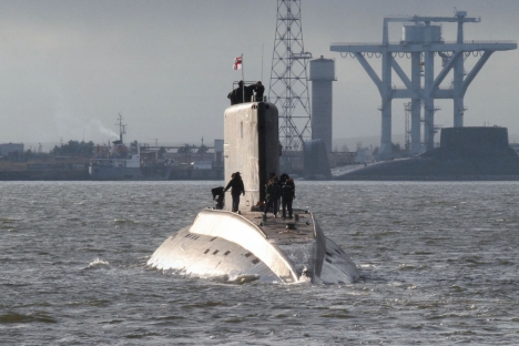
Rosoboronexport is in continued talks with Italy on the supply of S1000 submarines. However, these boats will not see action in either the Russian or the Italian navy. Instead, they will be sold exclusively to third-party countries. Experts at the Rubin Central Design Bureau for Marine Engineering and Italy’s Fincantieri completed the conceptual design of the S1000 a few years ago. The submarine was always intended for third-party countries. The Italian shipbuilding company presented a mockup in 2008, at the 21st International Naval Defense and Maritime Exhibition and at the Conference Euronaval 2008. According to Fincantieri Commercial Director Enrico Bonnetti, “the submarine’s architecture has been determined, equipment has been positioned, and an integrated combat system has been designed.” The S1000 is 56-meters long, with an outside hard-hull diameter of 5.5 meters (18 feet), a submerged displacement of around 1100 tons, a maximum depth of more than 250 meters (820 feet), and a top underwater speed of more than 14 knots. The submarine can carry a crew of 16, plus six special operations troops. The propulsion system includes two diesel generators, a battery, an electric motor and an AIP system with an electrochemical generator. Both Russian- and Italian-made equipment will be installed in equal amounts. The S1000 non-nuclear submarine is designed for anti-submarine warfare, reconnaissance missions, special operations support and transporting underwater subversive troops. The submarine can perform these tasks both in shallow coastal waters and in deep-sea conditions. Secondary objectives include anti-ship warfare, mining and naval aircraft support. The Soviet Union — and later Russia — have traditionally sold non-nuclear, diesel-electric submarines abroad. “Our key product in this global market segment is the Project 636 submarine, which is the current bestseller. But we are also promoting the new Amur-1500 submarine,” said Rosoboronexport head Anatoly Isaykin. “This is not a replacement for Project 636; it is an entirely new submarine that we will be promoting in parallel with Project 636. The Amur-1500 will also be in demand from international buyers, as it will be offered in different versions — including a version with an air-independent propulsion system that is becoming increasingly popular in the naval market,” Isaykin said. He added that sales of naval hardware through Rosoboronexport amounted to 20 percent of total military exports last year and were slightly higher than in 2011. The Russian navy will soon receive Project 636 submarines, as well. A keel-laying ceremony for a large diesel-electric Project 636.3 submarine named Stary Oskol was held at the end of last summer, at the Admiralty Shipyard. These submarines are now being built for the Russian navy, after being exported for 20 years. This submarine is expected to get a version of the new Kalibr missile system (exported as the Club-S) with a range of 1,500 kilometers (932 miles). There is one hitch though: to use this missile complex, a new combat command and control system is needed; its flaws have become one of the reasons behind the delays in building and deploying the Lada-class submarines for Russia’s navy. Project 636 submarines are armed with six torpedo launchers located in the bow; six torpedoes sit in shafts that are automatically reloaded after each launch. The torpedoes can be replaced with 24 mines, two in each launcher. Two torpedo launchers have been designed to fire high-precision, remotely controlled torpedoes. All launchers and their service systems can fire from both periscope and tactical operating depths. The launchers can be reloaded within 15 seconds. According to expert assessments, the submarine is low noise and “sees” better underwater than the most widespread American-made, Los Angeles-class submarines.
Underwater Planes.
Graham Hawkes can't quite put words to the feeling. It's like jumping off a cliff, but more peaceful. It is like sinking, but more purposeful. It is like flying but exactly the opposite. "Fun is an inadequate word for playing with technology the Navy doesn't have in a part of the world were few people can go," Hawkes explains to HuffPost Travel, somehow managing to sound more apologetic for being more verklempt than boastful about the fact that he has an underwater plane. Graham Hawkes has an underwater plane. That is both astounding and old news. After decades building the majority of submersibles used in scientific and military missions, Hawkes and his company DeepFlight began producing underwater planes -- buoyant vehicles that use hydrodynamics in much the way airplanes use the Bernoulli Principle effect -- in the 1990s. It was astonishing at the time and it still is, but what might be more exciting is that Hawkes wants tourists to join him. The sales pitch is pretty solid. "We can move for the first time with big marine animals," he explains, referencing the speed of his vehicles, which are considerably more maneuverable than normal submarines. "We had our first such encounter with a Great White Shark a few months back. Richard Branson was in the back…. We realized afterward that the shark had probably been challenging us over territory." Hawkes doesn't so much drop names as leak them. The names of the men who dive with him should sound familiar. Director James Cameron goes on dives. Richard Branson owns a 15-foot Merlin Series dubbed the Necker Nymph in tribute to his private Caribbean island and venture capitalist par excellence Tom Perkins owns a Super Falcon -- exactly like the one Hawkes pilots regularly -- which he used to keep aboard the Maltese Falcon, his famed superyacht. The reason Hawkes' clientele is so elite is quite simple: He sells something exceptionally expensive. Even though he's managed to bring the price of a basic expedition down from $100,000 to $10,000, flights on his Super Falcon are not exactly affordable. It doesn't help that his technology is so advanced that the Coast Guard forces him to give "flight lessons" instead of simple tours. Laws will catch up with technology, but bringing down costs on extremely complicated machines can be difficult -- commercial aviation remained a minor industry decades after the Wright brothers crash-landed at Kitty Hawk. This didn't stop Hawkes from settling on a goal after a recent meeting with representatives from Google and IDEO, the San Francisco design firm of the moment. "Everyone's feeling is that this technology is open to the billionaires club, but that we need to get the price way down for normal people," he explains. "We hope to go toward undersea tourism. What we've developed so far is underwater flight and it's fabulous. People should enjoy it." The hope is that a dive could eventually cost about the same as a flight on a glider or ultralight, which -- on Oahu -- would run a tourist between $200 and $300, a little more for longer trips. Hawkes doesn't purport to know when that day might come, saying the proliferation of underwater aircraft will depend on funding, which might be only a year or two away. What he is absolutely certain about is the experience he wants to share. Hawkes wants to take passengers and pilots alike into "the twilight zone," the area of the ocean above the inky blackness where large pelagic species hang out. Though his Falcons are now capable of diving some 3,000 feet, he says trips to that sort of depth somewhat defeat the point, which has ceased to be scientific or technical.
"Remotely operated vehicles can really play all the roles needed for science and military purposes, which frees up manned subs to be different," Hawkes says. "It is all about the experience now. We want comfort, safety and better vision. You have this panoramic view because the domes we use couple optically with water." On an upcoming trip to Hawaii, Hawkes plans to join a group of new pilots watching Humpback Whales through his perfectly engineered domes. The view of the pod should be rather better from the speedy submersible than from the ships that follow the cetaceans so tourists can snap pictures of upraised flukes. The underwater planes will be able to dive, loop and speed along with the whales. "It is a degree of freedom humans aren't used to," says Hawkes, expectation leaking into his rather proper London lilt. Even as space tourism companies get all the ink, underwater planes may call into question where the next tourist frontier actual lies: The Super Falcon is to SCUBA gear more or less what a 767 is to a good pair of walking shoes. The massive marine world could rendered suddenly accessible. But Hawkes' DeepFlight submersibles offer more than a chance to go someplace inaccessible. These remarkable pieces of technology may offer a specific feeling. It's like peace but more exhilarating, like discovery but more ecstatic; something hard to describe.
Back From The Dead.
February 22, 2013: A year after cancelling its Lada class diesel-electric submarines Russia has revived the project as part of a joint development effort with an Italian firm (Fincantieri). This effort will build the S-1000 submarine as well as revive other export versions of Lada. These were called the Amur class and the S-1000 began as the Amur 950. This was what the export version of the Lada was to be called, but working with an Italian shipbuilder the Amur 950 has been transformed into the cheaper (less than $200 million each) S-1000 class submarine. While Fincantieri has never built subs (just destroyers, aircraft carriers and patrol craft), it is one of the largest ship builders in Europe and has access to much Western military technology. The S-1000 will have a crew of only 16. Top submerged speed is 26 kilometers an hour. There are six torpedo tubes and an AIP (air independent propulsion) system to extend underwater endurance to 15 days or more. Instead of eight torpedo reloads, the S-1000 can carry a dozen commandoes. Lada was developed in the 1990s as the successor to the Kilo class but it was determined that there was not enough difference between the Lada and the improved Kilos being built. So Lada/Amur was canceled last year. One Lada was built and another is partially completed and will probably be finished as the under construction (and may be completed). The Russians are hoping that the S-1000 will spark interest in the various Amur designs. The largest of these is the Amur 1650, which is basically the Lada with some top-secret Russian equipment deleted. The Ladas have six 533mm torpedo tubes, with 18 torpedoes and/or missiles carried. The Lada has a surface displacement of 1,750 tons, are 71 meters (220 feet) long and carry a crew of 38. Each crewmember has their own cabin (very small for the junior crew, but still, a big morale boost). When submerged the submarine can cruise at a top speed of about 39 kilometers an hour (half that on the surface) and can dive to about 250 meters (800 feet). The Lada can stay at sea for as long as 50 days and can travel as much as 10,000 kilometers using its diesel engine (underwater, via the snorkel). Submerged, using battery power alone, the Lada can travel about 450 kilometers. There is also an electronic periscope (which goes to the surface via a cable) that includes a night vision capability and a laser range finder. The Lada was designed to accept an AIP (air independent propulsion) system. Russia was long a pioneer in AIP design but in the last decade Western European nations have taken the lead. Russia expects to have its own AIP in production within three years. Construction on the first Lada began in 1997, but money shortages delayed work for years. The first Lada boat was finally completed in 2005. A less complex version, called the Amur, was offered for export. There were no takers. The Ladas are designed to be fast attack and scouting boats. They are intended for anti-surface and anti-submarine operations as well as naval reconnaissance. These boats are said to be eight times quieter than the Kilos. This was accomplished by using anechoic (sound absorbing) tile coatings on the exterior and a very quiet (skewed) propeller. All interior machinery was designed with silence in mind. The sensors include active and passive sonars, including towed passive sonar. Russian submarine designers apparently believe they can install most of these quieting features into improved Kilos, along with many other Lada features. Two years ago Russia began construction of its second "Improved Kilo" submarine. These are mostly for the export market, although the Russian Navy is buying a few more of this improved model as well. The Kilos weigh 2,300 tons (surface displacement), have six torpedo tubes, and a crew of 57. They are quiet and can travel about 700 kilometers under water at a quiet speed of about five kilometers an hour. Kilos carry 18 torpedoes or SS-N-27 anti-ship missiles (with a range of 300 kilometers and launched underwater from the torpedo tubes). The combination of quietness and cruise missiles makes the Kilo very dangerous to American carriers. But for the Russians their Kilos are mostly for home defense. Nuclear subs are used for the long distance work. The Kilo class boats entered service in the early 1980s. Russia only bought 24 of them but exported over 30. It was considered a successful design, especially with export customers. But just before the Cold War ended in 1991, the Soviet Navy began work on the Lada. This project was stalled during most of the 1990s by a lack of money but was revived in the last decade. Russia has 17 Kilos in service (and six in reserve) and six Improved Kilos on order. More than that is on order from foreign customers.
Personal submarines emerge on boat market.

Bored with the luxury yacht? Personal submarines are a growing trend for the mega-rich. Microsoft co-founder Paul Allen and Russian billionaire Roman Abramovich - owner of the world's largest private luxury yacht, Eclipse - are among those who have their own mini-sub. Other ocean explorer types, such as British billionaire adventurer Sir Richard Branson and film director James Cameron, have custom-built subs. In March last year, Cameron descended 11 kilometres into one of the ocean's deepest nooks, the Mariana Trench, in his Australian-designed solo sub, Deepsea Challenger. Recreational subs could soon be jostling for space on board the world's luxury yachts, if latest design trends are any indication. The first family-friendly five-seater has hit the market and could soon be vying to become the new must-have toy of the mega-rich. The C-Explorer 5 was created by a Dutch submarine maker to accommodate four passengers and a pilot, and has been dubbed "the world's first subsea limousine". This airconditioned mini-sub - which will set you back a couple of million - can descend to a depth of 300 metres, reach speeds of three knots underwater and stay below the surface for eight hours. A range of larger recreational submarines that seat many more passengers are also on the market, but because of their size and price - in the tens of millions of dollars - they are mostly pitched at the luxury resort market. The market for recreational mini-subs is relatively new, according to Barry Jenkins, chairman of Superyacht Australia, which represents businesses that sell products and services to the superyacht industry. He says he spotted a mini-sub - a single-seater - for the first time at an international boat show about five years ago, then a double-seater appeared, and now the first five-seaters are arriving.
Brazil to build first nuclear submarines.
Brazilian President Dilma Rousseff unveiled a multi-billion-US-dollar naval plant Friday in southeast Rio de Janeiro state, where the country plans to build its first nuclear submarine with French technology. Brazil will build five submarines, including a nuclear-powered sub, in partnership with France, which agreed to transfer the technology to Brazil in a 2008 agreement. Rousseff highlighted the project, saying Brazil was now joining "the select club of countries with nuclear submarines," five members of the United Nations Security Council. Rousseff said Brazil can manage to dedicate itself to advanced industry without losing sight of other important goals, such as overcoming social inequalities. "Brazil can do it. It has all the conditions to fulfill its great role in the science and technology development, in the exploration of space, in the defense industry, but at the same time generate income and jobs, and deal with overcoming and eradicating poverty," she said. With an investment of 7.8 billion reals (about $3.9 billion), the naval plant, called the Metallic Structures Construction Unit, is designed to be part of a naval base and shipyard in the city of Itaguai. The plant will generate 9,000 direct jobs and 32,000 indirect jobs, according to the Defense Ministry. The first submarine is expected to be operational by 2017 and the nuclear sub is expected to roll off the assembly line in 2023. Rousseff said the nuclear sub will not serve for war, but will act as a deterrent. Defense Minister Celso Amorim defended Brazil's insistence on technology transfer as part of all its military purchases, saying "a country that depends on what others supply cannot be independent, nor defend its resources, its people or its place in the world."
Russia to Resurrect Titanium Submarines.
The Russian Navy will refit, modernize and recommission two Sierra class (Project 945) titanium-hull nuclear-powered attack submarines by 2017, the Zvezdochka shipyard said on Tuesday. The Sierra class has a light and strong titanium pressure hull, enabling these boats to dive to depths of up to 550 meters (1800 feet) and enhancing their survivability, as well as having a low magnetic signature. A total of four Project 945 and 945A submarines were built in Russia. In addition to the Karp and the Kostroma, the Pskov and the Nizhny Novgorod were built in the early 1990's and are currently in service with the Northern Fleet. The K-239 Karp (Carp) was the first Project 945 (Barrakuda) submarine, which entered service with the Soviet Navy in 1984. The K-276 Kostroma was commissioned in 1986 and had to be repaired after a February 11, 1992 collision with the American submarine USS Baton Rouge (SSN-689) while on patrol off Kildin Island near Severomorsk. The US Navy said the collision occurred more than 12 miles (22 km) from shore, in international waters. The shipyard signed a modernization contract for the Karp and the Kostroma with the Defense Ministry in December 2012 , a Zvezdochka representative told RIA Novosti. Karp has been sitting at the shipyard since 1994, he said, adding the submarine’s titanium hull “is in a very good condition” but a significant part of its equipment is missing. The submarines’ sonar and navigation systems will be replaced and their reactors refuelled, he said.
Russia to help launch Vietnam's Submarines.
Hanoi: Moscow will proceed with plans this year to help Vietnam launch a new submarine fleet and train the crews, Russian Defence Minister Sergei Shoigu said Wednesday. "This year our joint efforts will open a new page in Vietnam's navy - a new fleet will appear," Shoigu said after talks with his Vietnamese counterpart Defence Minister General Phung Quang Thanh. Shoigu said the two ministers discussed "crew training and preparation of the submarines", for which Russian military schools will provide assistance.
|
In 2009, Vietnam ordered a fleet of six Russian Project 636M diesel-electric (Kilo class) attack submarines, in a step seen as an effort to counterbalance China's expanding maritime influence in the region. The two nations remain in dispute over the Spratly Islands in the South China Sea. Earlier this week, Shoigu visited Khanh Hoa Province's Cam Ranh Port, which was Russia's largest naval base outside its territory until 2002.
17 One-Man Submarines .
Nordenfelt I, brainchild of Swedish inventor Thorsten Nordenfelt in 1884.

One of the two Resurgam, an early Victorian submarine designed and built in Britain by Reverend George Garrett in 1878-79. The Resurgam I was a hand powered, one-man submersible; the Resurgam II had a three-man crew, and was steam-powered.

A submarine motor car, invented by Michel Andre in 1937.

The Motorised Submersible Canoe (MSC)—nicknamed 'Sleeping Beauty'—was a British underwater reconnaissance or attack vehicle for a single frogman during World War II.

The Biber, a German midget submarine of the German Navy during the second World War, came armed with two externally mounted torpedoes.

The Welman submarine was a WWII one-man British midget submarine developed by the Special Operations Executive, but sadly was not very successful.

This K-250 one-person submersible was designed by retired US Navy WWII submarine captain George Kittredge in the 1960s.

Mikhail Puchkov's homemade personal submarine made a splash in the 1980s.

This is the one-man microsubmersible Mantis, designed by Graham Hawkes, British marine engineer and submarine designer. You might remember it from For Your Eyes Only.

C-Quester was one of the first mass-produced personal submersibles by the Dutch U-Boat Workx. Production was discontinued in favor of multi-passengers subs.

Newtsub Deepworker 2000, a single-person submersible by Nuytco Research Ltd.

Deep Rover, another single-person submersible by Nuytco Research Ltd.

The Innespace Dolphin prototype personal watercraft, which can ride on top of, leap out of, or dive under the water' surface.

AquaVenture WaterCrafts prototype sub, 2010.

Virgin Oceanic Expeditions' deep sea submarine, seen here in 2011, is currently still undergoing testing.

James Cameron's Deepsea Challenger made it about as far underwater as you can go.

Omer 8, a human-powered submarine recently built by students of the École de technologie supérieure (School of Higher Technology) in Montreal, Quebec.

China's submarines close to world level.
When commentating as a guest on People's Daily Online, naval expert Li Jie said that submarines independently designed by China are close to those of the United States, Russia, Germany and Japan in performance indicators, despite slight gaps from developed countries in terms of power plant and noise.
Li Jie explained that China's process of designing and building submarines has been actually getting mature and increasingly improved. By virtue of the intelligence and wisdom of Chinese people, China has made significant achievements in submarine design. The submarines independently designed by China have no big problems but some slight gaps in noise, material application and power supply. Li Jie added China's submarines are very close to nuclear submarines developed by the U.S. and Russia as well as conventional submarines developed of Japan and Germany in performance indicators, with narrowing gaps with them. Specifically, China has made improvements in mute effect, invisibility, material application, underwater hitting power, while we are also developing long-range, short-range, anti-ship and ballistic missiles. Additionally, we are also making effort to improve AIP submarines, and have made a great progress.
Submarine inventor thinks deep.
|
|
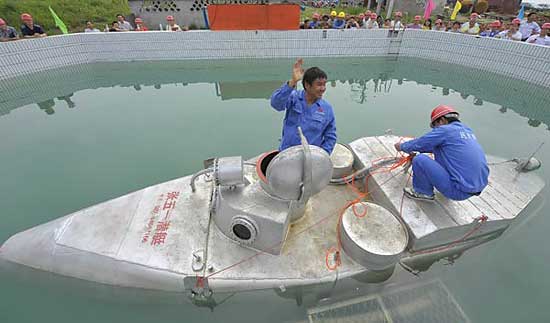
Zhang Wuyi is making it easier to farm cucumbers - at the bottom of the sea.
Crawling out of a small silver submarine after a 20-minute dive, Zhang was ready to show off his new submarine. "It's like an automatically-controlled undersea harvesting machine, and absorbs aquatic products like a vacuum cleaner," said Zhang, 37, who hopes to put the craft into large-scale production. The civilian sub is 6 meters long, 2 meters in circumference and can hold two people. The 9-ton craft can stay underwater for up to 20 hours. It is equipped with a camera, radar, positioning system and harvesting equipment. Since his first dive last August, he has received several orders and numerous calls from home and abroad. More than 20 people work in his boat company, located in a shabby bungalow in a suburban area, and they share a workshop with another factory. He has already invested 4 million yuan ($635,000) and is building a 10,000-square-meter plant. About 500,000 yuan was out of his own pocket, while the rest came from friends and other investors. In October, Cong Zhijie, who runs a sea cucumber farm in Dalian, Liaoning province, became Zhang's first and, so far, only buyer with a payment of 150,000 yuan. According to Cong, the submarine works well and saves him 10,000 yuan a day in divers' pay. Making a submarine, however, was not as easy as they imagined. "Our first submarine leaked like a sprinkler," Bao recalled. "Our second one looked functional, but it was stolen." Zhang's wife was strongly against his "stupid submarine business", but finally gave her tacit consent and support, especially after Zhang injured his left leg in an accident. "He is crazy about submarines," his wife said.
Tamil Tiger submarines at war museum
|
|
Visitors look at a vessel described as ‘Suicide submarine’ which is said to have been made by the LTTE and other boats captured by the Sri Lankan military, that are on display at the war museum in Puthukudurippu, some 360km north east of Colombo, yesterday. The Liberation Tigers of Tamil Eelam (LTTE) had fought a war for independence of the country’s Tamil-dominated North against Sri Lankan government forces for nearly 30 years until May 2009.
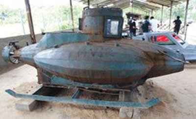
Vietnam’s Undersea Anti-Access Fleet
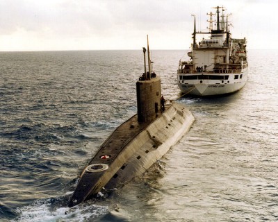
Anti-access strategy comes in many varieties. Vietnam is pursuing such a strategy, founded on a squadron of six Kilo-class submarines Russia is building for the Vietnam People’s Navy under a contract inked in 2009. In August the Vietnamese press reported that the first boat has been launched, and that all six will be delivered by 2016. The elusive Kilos should make a lethal access-denial force. While China’s People’s Liberation Army Navy operates Kilos itself, it has conspicuously neglected antisubmarine warfare hardware and techniques. It seems South China Sea waters will remain opaque to Chinese commanders for the foreseeable future despite the PLA Navy’s overwhelming superiority over the Vietnam People’s Navy.
First consider the politics of access denial, as we did with Iran and North Korea. Vietnam and China, like North and South Korea, are contiguous powers with vital interests at stake in the same waters. Vital interests like territory beget strong passions. Whereas Iran prizes its ability to manage offshore waters and skies more than the United States cares about operating there—and thus commands a political edge—both Hanoi and Beijing are impassioned about their maritime claims in the South China Sea. Both are prepared to wage efforts of serious magnitude and duration,commensurate with their material capacity to carry on the competition. Neither is likely to relent after dispassionately tallying up the costs and hazards of operating in waters its opponent wants to place off-limits. The result: a combustible situation.
Several tactical and operational characteristics of Vietnamese access denial are worth pondering. Its anti-access force, like all such forces, is asymmetric to the adversary it is designed to oppose. But unlike relatively balanced Iranian and North Korean forces, the Vietnamese access-denial contingent is almost purely one-dimensional. Hanoi doubtless chose well if it could select only one platform to execute its strategy. Submarines offer enormous bang for the buck, and they are survivable. Still, this also means that advances in Chinese antisubmarine warfare could nullify Vietnam’s effort to fend off the PLA Navy. Next, Vietnamese access denial could take on an offensive as well as a defensive character. Vietnamese Kilos could, say, loiter unseen off the Chinese naval station at Sanya, on Hainan Island, holding PLA Navy submarines at risk at the delicate moment when they are entering or leaving port—exposing them to enemy action.
Access denial—a strategically defensive posture—could therebytake on an escalatory hue.The inception of a Vietnamese undersea fleet will further crowd the already crowded waterspace of Southeast Asia, complicating efforts to discriminate among friend, foe, and bystander. China operates Kilos; so will Vietnam; even India could conceivably dispatch Kilos to the region. And this leaves aside the different submarine types deployed by Singapore, Malaysia, and other regional seafaring states. The chances for miscalculations and mishaps will only grow as access-denial strategies take shape.
A Soviet Foxtrot class diesel submarine, B-29, is steaming toward Mariel Bay, Cuba. In a game of high stakes cat and mouse, B-29 is part of a fleet of four submarines – spearheads of a mission to establish a Soviet naval base in Cuba – that had set sail from the Arctic port of Murmansk. Unknown to these submariners, American helicopters, aircraft and battleships, including an aircraft carrier, are scouring the ocean, looking for Soviet vessels. US Navy Admiral George Anderson – flouting orders from the Kennedy White House – issues instructions to his Caribbean flotilla to fire at the Soviet subs if they approach Cuba. The reckless Anderson, however, hasn’t reckoned with the cargo on board the four submarines his ships are hunting. Only a handful of the Soviet sailors on board the submarines know their vessels carry a nuclear torpedo – each equal to the bombs that wiped out Hiroshima. Vasili Arkhipov, the second-in-command on board B-59, is one of the officers privy to this knowledge. The gravity of the situation can be measured from the fact that the submarine crews –do not require Moscow’s permission to unleash Armageddon if they think they are under attack. As Soviet and American leaders mull nuclear war that could obliterate much of the earth, when paranoia on both sides means the slightest provocation could trigger nuclear war, things get worse. Time: 5.29pm Caribbean time. The US Navy ships locate B-59 near Cuba and start dropping practice depth charges, explosives intended to force the submarine to come to the surface for identification. A few days earlier, messages conveying the US Navy’s “Submarine Surfacing and Identification Procedures” were transmitted to Moscow. However, the submarines are out of radio contact and the instructions cannot be passed on to them. Now practice depth charges are not really bombs but small grenades designed to signal submarines to surface. The problem, however, is even minor explosions under water are magnified, sending shock waves through the submarine’s metallic hull. Out of contact from Moscow for days, the crew of B-29, under the command of Captain Valentin Savitsky, fears war has started. As Vadim Orlov, the submarine's radio intelligence officer, narrates to Russian journalist Alexander Mozgovoi in the book Cuban Samba of the Foxtrot Quartet, “The Americans encircled us and began dropping grenades that were exploding right next to us. It felt like sitting in a metal barrel with someone hitting it with a sledgehammer. The crew was in shock.” The bombardment goes on for several hours and some sailors lose consciousness as oxygen runs low and temperatures inside the submarine soar above 122 degrees F. Hot and sweaty inside their claustrophobia inducing vessel, with drinking water rationed to just one glass per sailor a day, the crew is “under terrible pressure at the moment, both psychologically and physically'' according to Mozgovoi. After an especially strong explosion shakes the submarine, Savitsky becomes furious and orders his weapons officer to arm the nuclear-tipped torpedo. “There may be a war raging up there and we are trapped here turning somersaults,” Savitsky says. “We are going to hit them hard. We shall die ourselves, sink them all but not stain the navy's honour.” But procedure requires Arkhipov and the political officer Ivan Maslennikov sign off too. A heated argument follows as Arkhipov vetoes the launch. His contention is total war cannot be unleashed without complete information. (It would have been madness to allow the launch, he later told his wife Olga.) As Noam Chomsky writes in Hegemony or Survival, if the torpedo had launched, a devastating response would have been a near certainty, leading to total war. Arkhipov eventually persuades his colleagues to surface the submarine and wait for further orders from Moscow. Standing down The US Navy vessels surrounding B-59, unaware they are cornering a submarine armed with a nuclear torpedo, now come closer. By this time, however, the hotheads on the American side have been asked to stand down, with the White House asking Admiral Anderson to not move a finger without its permission. (Anderson is dismissed after the crisis.) To indicate their intentions are not hostile, the US Navy plays a jazz band on the deck of one of the ships. The Americans think there is some sort of malfunction in B-29 but Savitsky declines offers of assistance and eventually turns around, heading for home base. B-29 is tailed by US Navy ships until it submerges on October 29. The three other Foxtrots also receive orders to abort their mission. The Cuban Missile Crisis is officially over. According to Orlov, the major danger during the crisis was not from the unauthorised use of a nuclear weapon but from an accident caused by the interaction of men and machines under the most trying of circumstances. The National Security Archive says, “Soviet submarine commanders were highly disciplined and unlikely to use nuclear weapons by design, but the unstable conditions on board raised the spectre of an accident.” Captain Joseph Bouchard, the author of a major study on naval operations during the missile crisis, supports this point when he suggests that the “biggest danger” was not from “deliberate acts” but from accidents, such as an accidental torpedo launch. If the Soviets had used nuclear torpedoes, by accident or otherwise, the US would have made a “nuclear counter-response.” While the Americans surfaced the Murmansk quartet, some Soviet submarines may have escaped US detection altogether. Says the National Security Archive, “While the four Soviet Foxtrot submarines did not have combat orders, the Soviet Navy sent two submarines, B-75 and B-88, to the Caribbean and the Pacific respectively, with specific combat orders.” B-75, a Zulu class diesel submarine, commanded by Captain Nikolai Natnenkov, carried two nuclear torpedoes. “It left Russian waters at the end of September with instructions to defend Soviet transport ships en route to Cuba with any weapons if the ships came under attack.” A day after the Arkhipov affair, another submarine, B-88, left a base in Kamchatka peninsula, with orders to sail to Pearl Harbour and attack the base if the crisis escalated into war. Commanded by Captain Konstatin Kireev, B-88 arrived near Pearl Harbour on November 10. There is no evidence the American spotted any of these ships. Under these circumstances which the American leadership and military were clueless about, nuclear war was a near certainty and it was purely Arkhipov’s courage – literally under fire – that saved the world. Despite being at the epicentre of the crisis, Arkhipov's role remained under wraps for a full 40 years. In 2002 in a conference held in Havana, Cuba, organiser professor Thomas Blanton of the Washington-based National Security Archive said, “A guy called Vasili Arkhipov saved the world.” The Russian sailor remained in the navy, rising to command first submarines and then submarine squadrons. He was promoted to rear admiral in 1975, when he became head of the Kirov Naval Academy, and rose to vice admiral in 1981. He died in 1998, at the age of 72. Robert McNamara, the US Secretary of State during the crisis, says one of the crew members told him at the conference that when Arkhipov and the other submariners returned home, they were reprimanded because they had not launched their nuclear weapons. If true, it has to be seen in the backdrop of Anderson's warmongering – there will always be those who prefer destructive war to a less than honourable peace. So long as history remains a chronology of kings, Khrushchev and Kennedy will take the headlines, leaving heroes like Arkhipov as a footnote. |
Russia, Italy re-visit S1000 non-nuclear sub project.
Russia and Italy have revisited the project of S1000 non-nuclear submarine. The project was frozen four years ago. This small submarine has been designed specifically for exports to the third world countries - Egypt, Morocco and others. According to latest reports, there will be only 20, not 50 percent of Russian components in the new submarine. However, Russia will be responsible for the promotion of the submarine on the market. In particular, not that long ago, the sides discussed an opportunity to restart the joint project. They named several specific measures to promote the submarine in the world market, and agreed to cut the cost of the ship. The last detail is the most interesting one. How is it possible to make a submarine cheaper and more affordable for international customers? According to reports that appeared in Russian and Western media, the project will become less expensive by abandoning the use of Russia-designed Club missiles underwater launch systems. This, in turn, would cut the costs for their transportation to Italy and customs clearance. According to latest agreements, the ratio of Russian and Italian components in the sub now makes up 20 to 80 respectively (vs. the previous 50 to 50). Thus, Russia will have only one-fifth in the future submarine. During the conceptual design stage, it was planned to equip the future submarine with Italian-French remote-controlled Black Shark torpedoes and Club complexes that may boast of many years of faultless operation. Why has Club become so expensive all of a sudden? The fact that the boat has been designed for sales to not very wealthy third world countries - Egypt, Indonesia and Morocco. However, the list of potential buyers includes not a very "poor" country - South Africa.
According to the Kommersant, Russian state company Rosoboronexport (defense export corporation) will be responsible for the international promotion of the submarine. This function originally belonged to the Italian side. The decision may be related to the fact that Russia sells most of its weapons through Rosoboronexport: the corporation has extensive international ties. The unique project S1000 was launched in 2004. The project is being developed by Italian shipbuilder Fincantieri and the Russian Central Design Bureau for Marine Engineering Rubin (based in St. Petersburg). The same design bureau works on strategic nuclear submarines for the Russian Navy. In particular, Rubin designs state-of-the-art nuclear-powered submarines of Borei and Borei-A projects. The works on S1000 sub were conducted in accordance with the technical inquiry and at the expense of the Italian Navy. The conceptual design was practically completed in 2008. Afterwards, the project was virtually shelved due to the lack of funds. It was assumed that a small non-nuclear sub would operate in warm waters, near islands and in shallow waters. It was originally believed that the construction of S1000 submarines would be Italy's prerogative. The time for the development of technical documentation and the construction of the lead ship was limited to 48 months from the signing of the first contract. Noteworthy, neither the Italian nor the Russian navies intend to pass S1000 submarines into service. The submarine will be produced exclusively for exports to third countries. Indeed, Russia will not be able to use such subs due to the geographical position of the country. Russia is washed by cold seas only, and transporting small submarines to tropical areas does not make any sense, officials with the Russian navy believe. With the length of 56.2 meters, the diameter of 5.5 meters and the displacement of about 1,100 tons, the submarine can reach the speed of up to 14 knots. The immersion depth of S1000 makes up 250 meters. The crew will consist of 16 men and six troops.
Canada and U.S. eye mini-submarines.
Special forces in both Canada and the United States are taking a close look at Canadian-made mini-submarines for the murky world of covert operations. The cutting-edge subs, some of which are built in Canada, are seen by some in the U.S. Special Forces community as essential for specialized top-secret operations against threats such as al-Qaida in coastal countries. One defence source in Washington, who spoke on background, said the U.S. navy has been impressed with the submarine rescue system it purchased a few years ago from B.C.-based International Submarine Engineering, which also sells 7.6 metre submersibles capable of carrying a handful of soldiers. The elite, secretive U.S. Special Forces is interested and also believes the subs would “be an ideal fit” for their Canadian counterparts, said the source, who was not authorized to speak publicly. No program has been requested or planned, however, said Brig.-Gen. Denis Thompson, the commander of Canada’s special forces. “It is an area of interest,” Thompson said in an interview with The Canadian Press. “It is potentially another tool for the toolbox.” Domestic concerns and the safety of the highly trained soldiers were some of the reasons Thompson asked staff to examine the boats in the spring of last year. Rather than operating in waters far from home, the military is concerned about missions in the three cold oceans that border Canada. “Given the condition of the sea water that surrounds Canada, once you put a diver in the water, he really can, depending on the temperature of the water, only be effective for so long,” said Thompson.“It’s all about stealth and extending the time you can leave a guy submerged — and by submerged, I mean hidden, depending on what the mission set is.” In Canada, the ultra-secret special-forces commandos known as Joint Task Force 2 have been paying particular attention to the country’s coastlines. Last year, it was revealed JTF-2 had turned to the private sector for help in early warning of possible terror threats coming from the sea. The organization tapped into an existing fisheries surveillance contract with Provincial Airlines Ltd., a subsidiary of Provincial Aerospace Ltd. of St. John’s, N.L., to monitor the movements of vessels of interest off the country’s coastline. At a rare public appearance last summer during the military’s annual northern exercise, JTF-2 commandos stormed a mock “vessel of interest” at sea while the prime minister, the defence minister and the media looked on. The subs aren’t cheap: Each one — some of them currently operate as underwater tour boats with up to 20 available seats — carries a price tag of $5 million. Sea Urchin Submersibles and Nuytco Research Ltd., a subsidiary of Can-Dive Construction Ltd., are the two other Vancouver companies with underwater technology that has caught the attention of the special forces community. Nuytco offers one-man and two-man deep sea diving suits. Can-Dive markets small diesel-electric submarines, but does not build them. Over the last 40 years, Vancouver has become a centre of excellence in deep-diving research and technology, said a May 4, 2011 briefing note prepared for Thompson.
Russia to salvage sunken N-submarines
The Russian defence ministry is planning to raise and scrap two sunken nuclear submarines in the northern Barents and Kara seas in order to prevent potential radioactive pollution of the area. The Izvestia newspaper said Thursday the ministry will announce an international tender, which may include companies from France, the Netherlands, South Korea and the US, as the Russian Navy does not have the necessary equipment to carry out deep-sea salvage operations. The B-159 (earlier named K-159), a November-class nuclear submarine, sank in the Barents Sea in August 2003, 790 feet down, with nine of her crew and 800 kg of spent nuclear fuel, while being moved for dismantling. The K-27 was an experimental attack submarine built in 1962 and decommissioned in 1979 due to its troublesome nuclear reactors. Her reactor compartment was sealed and the submarine was scuttled in the eastern Kara Sea in 1982 at a depth of 220 feet. After the sinking of the Kursk nuclear submarine in 2000, Russia has bought a number of deep-sea submersibles from Britain and Iceland, but these vessels are designed for search-and-rescue operations rather than salvage work. Two Dutch companies, Mammoet and Smit International, contracted by the Russian government, salvaged the Kursk in 2001. Meanwhile, the wreck of another sunken submarine, the Komsomolets, will most likely forever remain at the site where it sank in a 1989 accident, as a salvage operation would be too costly and dangerous. The K-278 Komsomolets nuclear submarine sank in the Norwegian Sea April 7, 1989, south of Bear Island. The submarine sank with its active reactor and two nuclear warheads on board, and lies at a depth of 5,560 feet.
HMS Conqueror’s biggest secret: a raid on Russia
It was dark, in the early hours, and the sea was freezing as Her Majesty’s Submarine Conqueror came to periscope depth. Her captain, Christopher Wreford-Brown, had been stalking his target methodically, a hunter in pursuit of wary prey. There she was, 1,000 yards ahead, slow-moving, seemingly unaware of the submarine coming up on her tail. Gathered around Commander Wreford-Brown in the darkened operations room, officers and men waited in silence, inner tension masked by outward calm. It was 1982 and this was the real thing. HMS Conqueror is famous, some would say notorious, for sinking the Argentinian cruiser General Belgrano. The nuclear-powered attack submarine, a type also known menacingly as a hunter-killer, that year became the first of her kind to fire in anger. The Belgrano was sent to bottom in short order, her ancient hull rent by two torpedoes: 323 men, many of them young conscripts, died. The Falklands war began in earnest that day, May 2 1982. But the ship now in the crosswires was not the Belgrano. This was August, almost two months after the liberation of the Falklands, and on the other side of the world, in the Barents Sea, backyard of the mighty Soviet Northern Fleet. Conqueror was sailing as close to Russian territorial waters as was legally allowed – or maybe closer. Submariners, a tight-knit community, politely disdainful of their surface counterparts, joke that there are two types of naval vessel: submarines and targets. Wreford-Brown’s target was a spy trawler – an AGI in Nato parlance, meaning Auxiliary General Intelligence. Crammed with interception and detection equipment, they were a ubiquitous presence during the Cold War, shadowing Nato exercises or loitering off naval bases. This one was special: Polish-flagged, she was pulling a device long coveted by the British and Americans, a two-mile string of hydrophones known as a towed-array sonar. It was the latest thing in Soviet submarine-detection technology and Conqueror’s job was to steal it. To do so, the bow was equipped with electronically controlled pincers, provided by the Americans, to gnaw through the three-inch-thick steel cable connecting it to the trawler. The name of this audacious exercise in piracy? Operation Barmaid. Thirty years on, and the story of this mission, classified Top Secret to this day, is being told. It may be that the Russian government is learning for the first time the fate of what was one of its most closely guarded devices. “This was a quite remarkable feat, a daring exploit that carried with it immense risk,” says the documentary maker Stuart Prebble, whose new book, Secrets of the Conqueror, discloses the existence of Barmaid. “When we think of the Cold War we think of Cuba and Berlin and missiles and tanks, but it was at sea, and under the sea in particular, where the East-West struggle was often at its most dangerous. “I have known about Barmaid for nearly 30 years and two years ago I approached the Ministry of Defence and asked that its details be released under the 30-year rule. They spent eight months thinking about it and eventually came back and said no. Their final position was that, although they wouldn’t help, they wouldn’t try to stop me writing about it.” Throughout the 1950s and 1960s the Anglo-Americans rested on their laurels, confident of their superiority in naval technology over the fledgling Soviet fleet. But as the 1970s wore on that confidence was eroded. Soviet submarines were not just becoming quieter and faster, they were able to turn the tables on their supposedly more advanced Western opponents. Submariners call it “bouncing”, the practice of creeping up on a hostile submarine before switching on active, wave-emitting sonar. The deafening ping in the earphones of the target crew tells them: “I’m here. If this was a war, you’d be dead.” Towed-array sonar is different. It is passive and does not emit a signal. It floats at a prescribed depth, trailing behind a ship or submarine, simply listening for enemy submarines. Because the hydrophones are spaced out, they can achieve a multi-dimensional fix on a target, and are less vulnerable to noise from the host vessel. The American and British navies imagined themselves to be far ahead in this technology and were disturbed to discover that the Russians were matching them.
Had they caught up through ingenuity, or by spying?
The issue was sensitive for the British, who had been plagued by spy scandals in the post-war period. The “Portland Spy Ring” had betrayed naval secrets, as had the Admiralty clerk John Vassall. The Americans took the lead, conceiving a project to capture a towed array and discover its origins. General Dynamics, supplier of kit to the CIA, built the pincer equipment, which was installed in British submarines. But why not use the bigger US Navy? “There are two schools of thought about that,” says Prebble, a former editor of World in Action. “The British believed they were selected because they had more skilled submariners, and exercises do seem to bear this out. British submariners tend not to play by the book to the extent that the Americans do. “The more cynical view has it that if a British sub was caught the diplomatic fall-out would be less severe than if an American one was involved. No one wanted to provoke a superpower confrontation.” Cutting a towed-array cable and making it look like an accidental loss was no easy task. Before Conqueror was fitted with the television-guided pincers, her sister ship HMS Churchill had tried to steam through an array to sever it from the towing ship. She was damaged and depth-charged for her pains. Conqueror made two attempts to use the pincers, in the Barents Sea and the Mediterranean, before her final attempt in August. “When crews heard about these pincers, everybody thought it was absolutely crazy,” says Prebble. “Their use demanded the most brilliant seamanship, coming up from below into the array’s blind spot and edging towards the cutting point only a few yards from the tow ship. The pincers were designed to gnaw rather than slice cleanly to give the impression that the array had snagged on an underwater obstacle and been torn off.” There, then, was Wreford-Brown, staring though his periscope that August night. The TV cameras were useless until a few inches from the target, so black was the Arctic water. Wreford-Brown and his officers had to fall back on mental arithmetic to calculate their distance from the target. “That was the genius of the exercise,” says Prebble. “There is a way of approaching the blind spot that involves going deep and then coming up at an angle, literally below the vessel.” The trawler’s propeller was feet away from Conqueror’s hull. A momentary miscalculation and a collision was inevitable. But nerves held and a connection was made. The pincer blades gnawed, and in seconds that seemed like hours the array was freed. Clamps held on to the cable as Conqueror dropped away to a safe depth, trailing the array by her side. “Everyone in the control room was tense,” says one of those present. “We were expecting at any time that we would be discovered and were ready to run, if necessary.” None of the crewmen who spoke to Prebble was prepared to confirm Conqueror’s position but the suspicion is that the operation took place inside Soviet territorial waters, just three miles from the coast. If discovered, the sub would have faced attack from Russian air and naval units. Once Conqueror reached a safe distance, divers were sent out to secure the array. The submarine later surfaced so that they could swim out again to haul the device aboard and bundle it in the hull. Did the crew of the AGI know what had happened? Even if they suspected foul play it would not have been in their interests to admit it to their superiors. A sojourn in the gulag might have followed. Immediately after Conqueror reached her base on the Clyde, the array was put on to an aircraft and sent for analysis in the United States. It is said that the name Conqueror was whispered with a certain reverence in the Pentagon for some time afterwards. Following the sinking of the Belgrano, much speculation surrounded the disappearance of the Conqueror’s logs. The assumption in some quarters was that they had been destroyed to conceal embarrassing details about the submarine’s movements before and after the attack on the cruiser. Prebble thinks otherwise. “I believe the logs were shredded or incinerated to hide the Barents Sea operation,” he says. “This was a top-secret mission.” The submarine arm is known as the Silent Service, partly because of its stealthy approach to warfare but also because of the secrecy attending its activities. Rarely does it receive public praise. Now, at least, we know of Operation Barmaid. The Conqueror’s crew had to celebrate their triumph in secret.
Indian and US navies to practice rescue of sailors trapped in submarines.
If an Indian submarine gets "disabled" deep underwater, the sailors are sunk since the country has only rudimentary submarine rescue facilities. Now, in a unique and complex endeavour, Indian and US navies are coming together to practice the rescue of "trapped" submariners from deep underwater.
The Indo-American submarine rescue exercise will kick off later this month, with the US Navy slated to fly down a submarine rescue system - a deep-submergence rescue vessel (DSRV) or a submarine rescue chamber (SRC) -- to Mumbai, sources said. The DSRV or SRC will then be shipped to the exercise area, where it will dive deep underwater to "mate" with the "disabled" submarine to rescue sailors in an intricate manoeuvre rarely practiced by Indian sailors. A DSRV or "mini submarine", equipped with pressurised chambers, sonars and cameras, can rescue 24 sailors at a time from a depth up to 610 metres after "mating" with a stricken vessel's hatch. At present, Indian sailors bank upon "submarine escape pressurized suits", or the help of diving support ships like INS Nireekshak, but they can be used only for relatively shallow depths. Navy's endeavour to procure two DSRVs of its own, for about Rs 1,000 crore, has been hanging fire for well over a decade now. As an "interim measure", India had inked a contract with the US Navy in 1997 for its "global submarine rescue fly-away kit" service, paying an initial $734,443 for it. But the agreement got derailed due to the sanctions imposed after the Pokhran-II nuclear tests in 1998. It was later revived in 2004 but there was huge delay in setting up the requisite infrastructure needed for submarine rescue operations.
It also included the fitting of "Padeyes" - holding devices welded into escape hatches of submarines to secure the DSRV - on Indian submarines. The American DSRV or SRC, as per the agreement, will be transported to India within 72 hours of an emergency.Proper submarine rescue facilities are critical for India since it has an ageing fleet of 14 diesel-electric submarines -- 10 Russian 'Kilo' class and four German HDW ones -- apart from the nuclear-powered INS Chakra leased from Russia earlier this year.There are also six French Scorpene "killer" submarines, being constructed at Mazagon Docks under the Rs 23,562 crore 'Project-75', slated for delivery in 2015-2020, three years behind schedule. India also hopes to make its own nuclear submarine INS Arihant operational next year, which is to be followed by two additional "follow-on vessels".
Submarine museum starts construction in Lvshun
Construction of a submarine museum in Lvshun started recently, reported Dalian Daily.With an investment of almost 150 million yuan ($24 million), the project will occupy an area of 16,044 square meters. The exhibition area is expected to total 8,369 square meters.The museum will exhibit the history of Chinese submarines, world submarines, and nuclear and strategic missile submarines.A high-tech exhibition hall in the museum will enable visitors to experience riding a virtual submarine with the help of 4D technology.The project is expected to finish before National Day next year.
Submarine with wheels.
|
The French defence firm, DCNS, recently unveiled what it is calling the SMX-26 submarine. The craft is a smaller submarine designed to operate in shallow waters and in coastal areas.The SMX-26 can remain on the seabed for a long time while conducting covert surveillance. Thanks to its shape, the SMX-26 can operate in waters less than 15 meters deep, according to DCNS.The company points out that the SMX-26 also differs from other submarine designs by its capability to conduct lengthy covert surveillance missions. It can rest on various types of seabeds, thanks to a system of leg-like struts fitted with deployable wheels, according to DCNS. Such lengthy missions are also helped by buoy-mounted flexible snorkels which allow the sub to recharge its batteries and to renew its air supply, the company notes in a news release. Its integrated and remotely-deployed sensors ensure comprehensive monitoring of its surroundings, both above the surface and underwater, the release adds. The sub can quickly deploy its offensive assets, including a team of up to six special forces operators, either on or near the surface, the firm adds.It is also armed with two weapons incorporated into its masts: a 20mm automatic cannon and a missile container for defence against aircraft attacks. The sub also carries two heavyweight torpedoes and eight lightweight torpedoes.The wheel concept reminds me of the Soviet submarines that were allegedly thought to be probing the coastlines of the Nordic nations during the Cold War. Those were believed to be equipped with tractor-like treads so the could move along the ocean floor |
Below is an artist’s concept of the SMX-26 submarine design concept, showing its strut-mounted wheels in extended position and its retractable power pods.

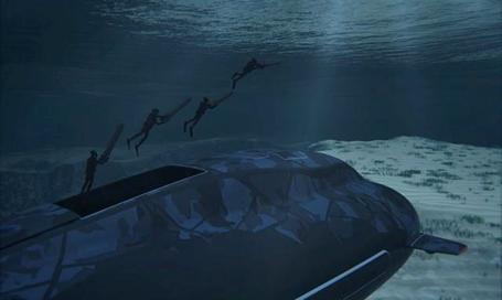
Ula Subs.
Norway’s ageing submarine fleet is not sufficiently stealth-capable, according to a former top naval officer.
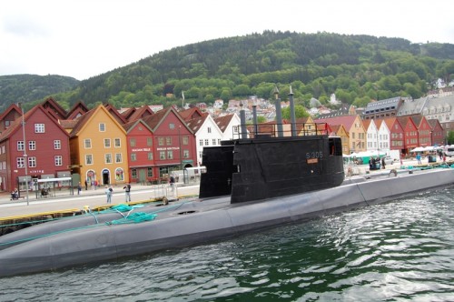
Norwegian Ula-class submarines, Bergen
Photo: Petr Šmerkl/Wikipedia
“The oldest [one] is 25 years old”, Rear Admiral Jan Gerhard Jæger (ret.) tells Aftenposten, “they undergo upgrades, but the ‘signature’ (identity) they leave behind in the sea remains unchanged.”Norway’s six Ula-class submarines, all based at Bergen’s Haakonsvern Naval Base, western Norway, were ordered in the ‘70s during the Cold War. These replace the then ageing Kobben-class ones. The Ula-class submarines were a multinational cooperation on behalf of the Royal Norwegian Navy. The hull sections were produced in Norway, and German company Thyssen Nordseewerke in Emden assembled them.Norway’s Kongsberg Group built their combat systems, Germany the attack sonar, and the flank sonars are French-made. The vessels were delivered between 1989 and 1992.Upgrades have been performed on the periscope as part of modernisation work to keep them in service until 2020. These are also currently being carried out on the hull, propulsion, and integrated ships systems.Installation of new electronic warfare support measures and communication equipment (TADIL-A/Link 11) is part of the programme too, with ongoing work on the weapons control, sonar, and decision support systems, among other things.TADIL-A/Link 11, a NATO-employed secure half-duplex radio link, can be used on High Frequency (HF) or Ultra High Frequency (UHF).It is mainly for exchanging digital information such as radar tracking among shipboard, airborne, or land-based tactical data systems.According to Norwegian Royal Navy information, the Ula-class submarines “makes it possible to operate in the entire maritime domain, including under water.”“The vessels can operate undisclosed over longer periods of time. They are hard to detect and has the ability tie up significant hostile resources.” “The vessels are currently being upgraded to ensure they are relevant to the tasks they will be solving until 2020”, she stated, “[...] We’re world class when it comes to conventional submarines.”“They can operate hidden and surface vessels cannot discover them easily. Nevertheless, technology for surface vessels and submarines has developed, meaning these need updating.”Commander Krey tells The Foreigner Norway upgrading the submarines “is not different to what other countries do.”The Ula-class submarines are 59 metres long, 5.4 metres wide, and 4.5 metres deep (about 193.5 by 17.7 by 15 feet).Speeds are 11 knots surfaced and 23 knots submerged, with capacity for a crew of 21+.“It’s a potent conventional submarine,” Navy press spokesperson Commander Nils Kristian Haugen says.No decision regarding new submarine purchase has been made, the military’s Colonel Dag Rist Aamoth explains, “But there is an ongoing project looking at possible Ula-class end-of-life replacement or a further upgrade and life extension of the submarine.”
Drone Submarines.
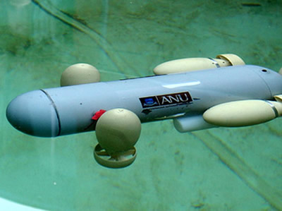
Surveillance drones in US airspace is soon to be inevitable, but what about unmanned vehicles patrolling the seas? The Pentagon is working hard at perfecting a stealth underwater drone for maritime monitoring. Science Applications International Corporation of McLean, Virginia was recently awarded a contract from the Pentagon’s Defense Advanced Research Projects Agency, or DARPA, valued at over $58 million. With that funding, researchers have already begun working on an underwater vessel that will take the surveillance abilities that make aerial drones such a hot commodity and use it to send an unmanned submarine to sweep the sea for potential hazards.According to DARPA, enemy submarines are being built right now with competing technology, allowing America’s foes to perhaps find a way to sneak unmanned vessels of their own around US bases across the globe. That’s why the Pentagon has contracted a team to work on an Anti-Submarine Warfare (ASW) Continuous Trail Unmanned Vessel, or ACTUV, which they say will be able to address a serious emerging threat.“The growing number of adversaries able to build and operate quiet diesel electric submarines is a national security threat that affects US and friendly naval operations around the world,” writes DARPA. Still in the early days of testing, the Science Applications International Corporation is now in the midst of stages two through four of the process, which involve design, construction and demonstration of a submarine that can spend months underwater without requiring a single human operator on board. If their prototype proves successful, software will need to be scripted, a finalized ship will be built, and the drone sub will begin supporting at-sea government testing. DARPA predicts the ships will be ready to go underwater for their first test runs in mid-2015.In addition to scoping out any underwater adversaries interesting in attacking the United States or its bases, these drone subs could also be deployed to search for any other vessels that could compromise America’s interest. Earlier this year RT reported on the growing number of stealth subs used to move narcotics from Central America into the US, and just this month it was reported that a nuclear-powered Russian attack submarine sailed to within 200 miles of the United States before it was first spotted. Sending subs into the sea to search for these types of hazards is already an option, but deploying unmanned vehicles in dangerous situations might soon be the norm.
Iran near self-sufficiency in submarine industry.
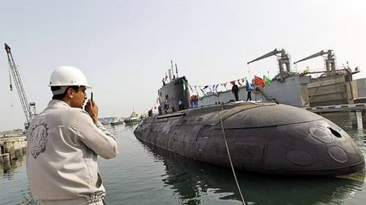
Iran's Navy launched the super-heavy Tareq 901 submarine, overhauled by Iranian experts.
Iran’s Navy Commander Rear Admiral Habibollah Sayyari says the Islamic Republic is on the threshold of self-sufficiency in the submarine industry. “Today, the Islamic Iran has reached the threshold of self-sufficiency in manufacturing, equipping and repairing the most complicated and modern types of submarines in the world,” Sayyari said Wednesday. He added that the production of submarine equipment has also been completely localized over the past decade. Iran has so far launched different classes of advanced submarines including Fateh, Ghadir, Qaem and Nahang. On Tuesday, Iran's Navy also launched the super-heavy Tareq 901 submarine, overhauled by Iranian experts. Over the recent years, Iran has made important breakthroughs in its defense sector and attained self-sufficiency in producing important military equipment and systems. The Islamic Republic has repeatedly made clear that its military might is merely based on the nation's defense doctrine of deterrence and poses no threat to other countries.
Algeria Buys Submarines from Russia.
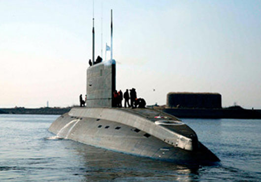
Rosoboronexport received a request from Algeria for two Kilo-class diesel-electric submarines, a source in defense ministry told Kommersant. This was confirmed by an informed insider. According to the sources, upon recommendation of Federal Service for Military Technical Cooperation, Russian Ministry of Trade and Industry appointed JSC Admiralteyskie Verfi shipyard executor of the order. In 2010, Admiralteyskie Verfi delivered two Kilo-class subs to Algeria under the $600-mln contract signed in 2006, specifies Kommersant. Cost of the current contract is not disclosed. Kilo-class low-noise submarines dubbed by Americans as “Silent Death” are among the most popular Russian military products abroad, reports the newspaper. The project was developed by the Rubin Design Bureau. Subs of this project are used for destruction of underwater and surface combatants, protection of naval bases, coastline, sea lanes, conducting reconnaissance etc. They are considered one of the world’s most silent submarines. Length is 73.8 meters; beam is 9.9 meters; displacement is 2,350 cubic meters; submerged speed is 20 knots; test depth is 300 meters; crew is 52 men. Armament includes 4 missiles (the number can be enlarged), 18 torpedoes and 24 mines. Project 636 constitutes modernized Project 877EKM Varshavyanka submarines built for seven countries in 80-90′s, including Algeria. If the contract is signed, Algerian Navy would operate six Russian-made submarines, reports Kommersant. Signing of a firm contract is expected in 2013, said one of the insiders. He admitted, however, that terms of the contract can be postponed due to controversy around the executor’s candidature, writes Kommersant.
Columbia Inducts Two Former German Submarines.
The Columbian Navy announced today that it has inducted two former Type 206A submarines from Germany. Under a contract concluded between Colombia and the HDW shipyard, the latter "tropicalized" the two submarines, which were originally designed for use in the Baltic. These activities have included the technical integration of the Naval Arsenal is intended. "Intrepido" and "Indomable" will support two other submarines built by HDW in Kiel for the Colombian navy, "Tayrona" and "Pijao" (Type 209). Until March 31, 2011, "Intrepido" and "Indomable" belonged to the German navy, with the sail numbers U 23 and U 24.
Drug Submarines For The Next Generation Smuggler.
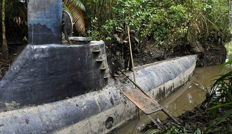
Drug submarines are becoming increasingly popular for drug smugglers seeking a new DIY solution to bring more of their drugs into America. Among the confiscated marijuana catapults and engineered mega-tunnels, a new fleet of diesel-powered, fully submersible narco-subs are seeking to make their mark. The latest fiberglass models are also a far cry from the beginning, when feds first discovered rickety, barely-submerged metal husks. Now, some of the latest discoveries come complete with air conditioning, shark paint jobs, and quick-scuttle technology, to sink the ship easily with the drugs inside. Drug-smuggling submarines were first heard of in the 1990s, but they didn’t get much attention until 2006 in the eastern Pacific Ocean when the US Coast Guard intercepted a semi-submersible they called “Bigfoot.” Since then, federal authorities have seized at least 25 ships like it in the Pacific. Including the Pacific Ocean, these narco subs have recently cropped up tin the Caribbean, with the Coast Guard intercepting five in the last year. In a raid in August 2011, Coast Guard officers intercepted a load of 15,000 pounds of cocaine, worth $180 million, in a drug submarine off of the Honduras coast. They have since discovered three fully submersible models capable of hauling 10 tons of cocaine, and conceivably able to travel from Ecuador to Los Angeles, coming up at night only to recharge their batteries.
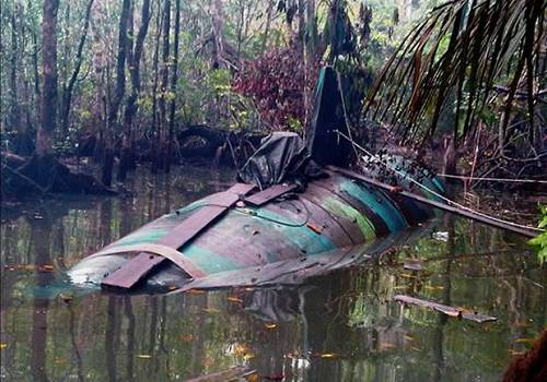
Cmdr. Mark J. Fedor of the Coast Guard, who commands the Mohawk, a 200-foot vessel who interdicted the first drug submarine seen in the Caribbean last year, stated: “These vessels are seaworthy enough that I have no doubt in my mind that if they had enough fuel, they could easily sail into a port in the United States.”There are more than ships, cutters, and helicopters working to intercept these new narco-subs. They are helped by a command center, known as Joint Interagency Task Force-South, which combines workers from the Departments of Homeland Security, Justice, State and Defense, as well as intelligence agencies and liaison officers from over a dozen nations who analyze threads of information on drug trafficking. The task force is 600 people strong, and they cue ships, aircraft, and counternarcotics units on the ground, in order to intercept drug smugglers up and down the hemisphere. In 2011 alone, these interdiction missions captured 129 tons of cocaine on its way to the US, more than five times the amount of the cocaine seized through operations in the United States during the same time (they captured 24 tons of the drug). Despite this promising statistic, however, three-quarters of potential drug shipments identified by the task force are not intercepted, because there aren’t enough ships and aircraft available for this missions to capture the drug submarines.
The Feds Can't Catch the Cartels' Cocaine-Filled Submarines.
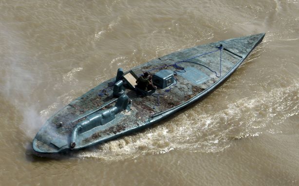
With three-quarters of potential cocaine shipments sliding under their noses, United States authorities are having a hard time keeping up with the Latin American drug cartels. Part of the problem, a new report in The New York Times says, is the fact that the famously daring and elusive drug-running submarines aren't just operating in the Pacific Ocean any more. These diesel-powered vessels have taken the Caribbean by storm, and the technology powering them is getting more sophisticated. Although they captured 129 tons of cocaine on its way to the U.S. last year, the Coast Guard thinks that close to 500 tons could now be making it through. "My staff watches multi-ton loads go by," Rear Adm. Charles D. Michel told The Times. Part of the problem is a new class of fully submersible craft, three of which have been seized in recent weeks. (Before, the subs were only semi-submersible, depending on a snorkel to bring in air for the engine.) These new drug-running subs are capable of carrying up to ten tons of cocaine at a time and can run from Ecuador to Los Angeles without coming up for air. On top of it all, officials are also worried that these subs could be used by terrorists. Of course, running drugs in subs is nothing new. So-called narco-subs first started making headlines about ten years ago when cartels, mostly Colombian at that point in time, started switching from the surface-level speedboat technique to using rudimentary fiberglass-and-wood vessels that could zoom under the surface. U.S. authorities called the first captured submarine -- a 49-foot-long vessel carrying four men, an AK47 and three tons of cocaine -- Bigfoot because they weren't even sure it existed until they spotted it. Since then the subs have only grown more sophisticated and more frequent, so U.S. authorities are working overtime. Michel says that drug interdictions are already up 50 percent in 2012. Success, as we mentioned before, is spotty at best.
Ukrainian builds own submarine.
Using his own bare hands, a 48-year-old Ukrainian man has created a three metre submarine, capable of diving 50 metres and travelling at a speed of 6.5 kilometre per hour. Vasyl Chikur spontaneously decided he wanted to build one a few years ago and so took two years out of his life to create his personal vessel, Reuters reports. 'My first impression was unbelievable, I felt as if I was flying in outer space. I couldn't calm down till night. It was such an euphoria, which I can't even describe,' Mr Chikur told Reuters, recalling his first dive. His vessel cost him just over $12,000 and he's now planning on improving it for marketing and business purposes. '(I'm planning) to tune it to the condition when it can to do aerobatics in the water and then to try to build submarines for sale or for rent. For two, three or five people. But first of all I have to do is to persuade our registration authority to register the boat,' Mr Chikur told Reuters. His main career of drilling and communications equipment will be put on hold while he tries to create bigger and more sophisticated boats for sale.
Wuhan man building business of submarines.
A man in central China's Hubei Province who has invested more 3 million yuan (US$474,419) in building small submarines on his own has completed his first deal and is now trying to attract more investment to expand his buoyant business. Zhang Wuyi, 37, a laid-off textile machinery factory worker in Wuhan, has received three orders this year, with each submarine selling for about 200,000 yuan, the Wuhan Evening News reported yesterday. Zhang told the paper that he learned from Li Mingyu, who was honoured as "the first manufacturer of a self-made submarine in China" and led Zhang into the business. "At first I was just an onlooker, watching Li building the submarine just like watching a joke," said Zhang. But when he realized there was a great market demand for small submarines, he decided to participate. He started by renting his original factory workshop to use as his own manufacturing base. He has about 10 employees. Zhang's chief engineer, surnamed Li, used to work in the shipbuilding industry. He told the newspaper that he was moved by Zhang's persistence and decided to help. With Li's assistance, Zhang successfully built his first commercial submarine and sold it to Cong Zhiwen, a businessman from Dalian, a north-eastern city. Li said the submarine can dive to about 30 meters and work 10 hours a day. It can hold two people and is equipped with a mechanical arm and underwater camera.
Ukraine's Only Submarine on Sea Trials.
Ukraine’s only submarine, 40-year-old 'Zaporozhye', has left the port of Sevastopol on the Black Sea for sea trials after many years of repairs. The Soviet-era Foxtrot class (Project 641) diesel-electric submarine stood grounded at a dock in Sevastopol for years without repair and became a symbol of the demise of Ukraine’s navy. Russian engineers repaired and serviced the submarine and a crew of Ukrainian submariners was trained at Russian naval bases. “The sea trials of the Zaporozhye submarine is an important event for the Ukrainian navy,” Defense Minister Dmytro Salamatin said. “Successful sea trials will ensure the revival of Ukraine’s submarine fleet.” The trials will test the submarine’s power plant and other key equipment while sailing on surface. Though the submarine was built 40 years ago, the vessel has been upgraded with new equipment and will certainly raise the combat capability of the Ukrainian navy. Submarines of this type are most efficient in the Black Sea as they feature low radar and noise signatures.
Human error causes submarine grounding.
A Board of Inquiry (BOI) has found that human error was a key contributing factor in the grounding of HMCS Corner Brook in Nootka Sound June 4, prompting Commander Royal Canadian Navy to relieve LCdr Paul Sutherland of his command. The submarine struck the south eastern wall of Zuciarte Channel, more than 500 yards from its intended position while the boat was conducting Submarine Officer Continuation Training. A military BOI formed to look into the matter, spoke to 15 witnesses prior to reaching its findings. "The BOI concentrated on the events that happened on board, on that day, so most [who were interviewed] were members of the crew or riders at the time," says Capt (N) Luc Cassivi, Deputy Commander of Canadian Fleet Pacific. The BOI determined the submarine's technical systems did not contribute to the incident. Submarine commanders usually give the boat a buffer zone to allow for any errors in equipment or ocean currents when submerged. The established practice of recognizing what is referred to as a "pool of errors" was not properly followed in this case.” This grounding was avoidable," said Capt (N) Cassivi. "It was caused by a failure to properly account for the positional uncertainty of the submarine in accordance with approved dived submarine navigational practices and techniques when operating in confined waters."
The World’s Biggest Nuclear Submarine Is the Sneakiest
While the Red October may not have been an actual submarine, the Russian Typhoon class that it’s based on certainly is. Turns out, Hollywood didn’t have to embellish many details for the film—Typhoons really can sneak up on you. The Typhoon is a class of nuclear-powered ballistic missile submarines developed by the USSR and deployed throughout the 1980s. The fleet of six submarines were built at the Severodvinsk Shipyard on the White Sea. The largest submarines ever constructed, they measure 175 meters long with a submerged displacement of 48,000 tonnes. The Typhoon class is capable of staying submerged for up to three months at a time. These massive ships employ a five-layer, pressurised hull—the outermost of which is covered in sound-dampening plates—which allows the ship to dive to a maximum depth of 400 meters. The five-layer style also allows for an overall wider design than a conventional submarine. This helps create the necessary living space for the Typhoon’s crew of 160 sailors, and it provides additional protection against hull breaches. A Typhoon class sub is powered by two OK-650 pressurised-water nuclear reactors, each of which provides an excess of 250,000 HP. This allows the subs to reach a top speed of 22 knots on the surface and 27 knots when submerged. The Typhoon was designed to compete with America’s Ohio class subs, which were capable of carrying up to 192 100-kiloton nuclear warheads. Typhoons carried a primary cache of 20 RSM-52 SLBMs, each of which contained up to 10 MIRV warheads. These missiles were designed so that a Russian sub would be able to launch them safely and discreetly from beneath the ocean’s surface. The missiles were also capable of breaking through Arctic ice floes during launch. The missile systems that the Typhoon class use are reaching the end of their service lives. Three of the ships have been retired, two have been placed on reserve, and the flagship of the Typhoon fleet, the TK-208 Dmitry Donskoy, has been retrofitted and is in field testing with a new weapon system.
Canadian Submarines.
Back in the 60's the Royal Canadian Navy fielded a small number of reasonably capable submarines, the Oberon-class boats we bought from the UK. We had five of these subs. Introduced in 1965 they were decommissioned in the late 90's, a commendable service life. As the Oberon boats were being phased out Canada went shopping for replacements and, voila, the Royal Navy happened to have four "nearly new" Upholder-class subs it was looking to unload. These subs had been mothballed after just four years of somewhat chequered service. During construction of the first boats it was recognized that the weapon-discharge system design did contain flaws. The torpedo tube slide valve controlling operation of the torpedo tube doors could have, under certain system failure conditions, allowed the opening of the inner door while the outer door was open. The flaw was quickly fixed in the first three boats and the modifications included in the fourth boat while still under construction. Miscalculations were made in the design of the main-motor control circuitry. During the sea trials of Upholder, when performing the specified trial for an emergency reversal ("crash back"), a flash-over incident occurred, which resulted in the complete loss of all power and propulsion. On investigation, this was traced to a fault in the design of the control circuitry insulation, resulting in a battery short circuit current of more than 60,000 amperes. The diesels were originally designed for use in railway locomotives, and were not intended to be rapidly stopped and started. Shutting them down after snorkelling led to many failures. Similarly, the motor-generators were operated at full power for longer than expected, and consumed brushes and filters rapidly (the brush problems were not specific to the Upholders, and were a widespread issue on all UK RN vessels at that time). Canada bought these boats in 1998 only to find them chock full of gremlins. Fourteen years later the Canadian navy hopes to have one of them operational this year. It's now thirty years or more since those submarines became operational with the Royal Navy. Thirty years in submarine years is just about a full lifetime. So not only are Canada's subs about to enter service as geriatrics, they're no longer state of the art in the engine room where it really counts. The propulsion units of these diesel/electric subs are a somewhat advanced version of what submarines have used since WWI. That is so yesterday. A big disadvantage to conventional, or non-nuclear, subs has been that they could use their diesel power only while surfaced or while running just below the surface using a snorkel. One way or another they needed a source of air to run at full power. Nuclear boats were air independent and could chug along in the ocean depths for months at a time. Conventional subs bridged the gap recently with the introduction of air-independent propulsion engines. The latest German submarines of the 212 class use fuel cell technology that allows them to cruise fully submerged for weeks. This gives them an endurance capability vastly greater than our vintage subs and somewhat similar to nuclear submarines without the noise penalty of nuclear power units. Why does this matter, especially to Canada? For the first time in our nation's history we're probably going to have a genuine need for a submarine capability, that's why. The Arctic Ocean is going to become ice-free. That means Canada's northern waters are destined to become a major shipping route. It also means the Arctic Ocean will see something akin to a gold rush in the pursuit of seabed resources from oil and gas to mineral wealth. That in turn will fuel tensions over unresolved territorial disputes. That will also lead to new and expanded military presences in the far north. There will be no shortage of legal, diplomatic, commercial and military muscle-flexing in the decades ahead. Right or wrong, like it or not, Canada will need to establish and maintain a credible presence to uphold our sovereignty and protect against encroachment. You snooze, you lose. It's that simple. Submarines, especially of a type our potential rivals cannot readily detect, are essential for defending Canada's north. That means we need modern boats that are capable of silent, extended patrolling underwater. Let's face it, if Harper gets his way and Canada does wind up saddled with a few dozen single-engine, limited range, minimal payload F-35s, we can pretty much kiss goodbye any meaningful ability to defend the vast north from the air. We will need something to pick up the slack. Which brings us back to Canada's not-ready-for-primetime Victoria class subs. It is possible to retrofit those boats with air-independent propulsion systems but is it feasible given their age, remaining usable life, ongoing reliability questions and the substantial cost? Anyone who has owned an old car knows that sometimes you have to cut your losses and get a new car. It's time for the Canadian government to admit that the Victoria boats were yet another disastrous mistake brought to us by the dimwits that populate our National Defence headquarters. It's probably time to stop throwing good money after bad. It's probably time to go shopping for new boats. This time we might even be able to get new for cheap. Greece has several new boats on order from the Germans and it's looking like Greece is a bit short on Euros to pay for them.
Nations face-off beneath the waves.
The Yomiuri Shimbun Chinese submarines deployed at a naval base at Yalong Bay, Hainan Island, China The world has been thrust into a period of great change due to China's emergence and the geopolitical decline of Western powers. This series of articles deals with the formation of a new international order, and potential leadership changes in the United States, China and Russia this year. This first instalment focuses on an underwater tug-of-war between U.S. and Chinese submarines in the Pacific Ocean. An underwater tug-of-war is intensifying among countries such as China, Russia and the United States in the seas around Japan. Vietnamese Defence Minister Phung Quang Thanh, who comes from Vietnam's army, requested an inspection of a Maritime Self-Defence Force submarine when he visited Japan in October. He visited the Makishio, a main submarine of the MSDF Submarine Flotilla 1, in the city of Kure, Hiroshima Prefecture. Made in Japan, the state-of-the-art submarine boasts a displacement capacity of 2,750 tons and is 82 meters in length. It can travel underwater silently and has stealth capabilities. The Vietnamese defence minister paid close attention to the Makishio's interior. It was rare for the MSDF to show the military leader of a non-allied country the craft's interior, which is full of secrets. The commander of the Vietnamese Navy also visited Japan in December. Vietnam's military leaders visited Japan and contacted the MSDF in succession because the country is now rapidly trying to build its own submarine fleet. The first of six Kilo-class Russian-made submarines Vietnam purchased in 2009 will be delivered in two years. Because it can travel silently underwater, a submarine is a strategic weapon. It has the offensive capability to destroy enemy ships and disrupt their transportation routes. It also has spying capabilities and can collect intelligence right under an enemy's nose. The very existence of a submarine can restrict an enemy's moves. Vietnam will employ submarines to deal with territorial disputes with China in the South China Sea. A Vietnamese source said the nation has begun receiving assistance from Russia and India to train its submarine crew members. "We've already made a request to Japan to help us operate submarines and train crew members," he said. When the Vietnamese defence minister visited Japan, Tokyo and Hanoi confirmed a multilateral cooperation security policy out of concern for China's ambitions to increase its influence in the South and East China seas. The two governments also signed a memorandum to promote mutual defence exchanges. Submarines would also help counter Beijing's strategy of denying the U.S. Navy access to and intervention in seas close to China. Beijing possesses more than 70 submarines, including state-of-the-art Jin-class nuclear submarines that can launch ballistic missiles. They have reportedly been deployed to China's Hainan Island, where the nation's largest submarine base is located. Hong Kong media have reported that Beijing has an ambitious project to build 30 new submarines by 2020. This suggests China, the world's second-largest economic power, is seriously considering a "private" plan to divide the Pacific Ocean into two and control one of the halves. The United States would control the other half, with Hawaii at its border. A high-ranking officer of the Chinese Navy revealed the plan's existence to the commander-in-chief of the U.S. Pacific Command in China as a "private proposal" in 2007. This plan, however, is a grave challenge to the United States and runs counter to the very idea of freedom of navigation in international waters being part of its national credo. "China's emergence as a regional power has the potential to affect the U.S. economy and our security in a variety of ways," according to a defence strategy report released by U.S. President Barack Obama's administration on Jan. 5. It declared the U.S. military will abandon its conventional strategy to prepare for large-scale wars in two regions at the same time, and "will of necessity rebalance [efforts] toward the Asia-Pacific region." The U.S. submarine fleet, the strongest in the world, would head toward the west in the Pacific Ocean. Washington is planning to deploy 60 percent of its aircraft carriers and submarines in the Asia-Pacific region. Attack submarines would be deployed forward to hunt enemies and protect U.S. aircraft carriers from surprise attacks by Chinese submarines. According to a report issued by the U.S. Congressional Research Service, the U.S. Navy has deployed three attack nuclear-powered submarines in waters near Guam. The report also says three others of the same type and two cruise-missile submarines have been deployed in waters off the U.S. mainland's west coast. A U.S. nuclear submarine is also planned to visit the western part of Australia. A 21st-century version of the "Great Game" has begun between the United States and China under the western Pacific. With Vietnam joining the link between the United States and its allies, a loose but broad coalition is forming against China. In the northern part of the Pacific, Russian nuclear submarines, meanwhile, are observing the United States and China's moves.
Subs Going Down in Strength, Numbers.
The U.S. Navy submarine force will lose significant numbers as well as capabilities over the next 18 years, according to a group commander. Rear Adm. Richard Breckenridge, USN, the commander of Submarine Group Two, outlined the reductions for a panel audience at West 2012 in San Diego. These reductions are part of an overall effort to reduce the size of the force. The number of attack submarines will decline from 55 to 40 by 2030. All eight SSG cruise missile submarine crews will be removed from the force. Adm. Breckenridge pointed out that the submarine force has declined from 21,000 to 16,000 sailors over the past 12 years. Yet, the service maintained the same number of crews. With the new submarine reductions, the Navy will go from 91 submarine crews to 60 crews amid a more challenging global security environment. Undersea forces are undergoing a transformation that began with the Virginia-class boats, the admiral observed. Not since the days of the USS Nautilus, he said, has the Navy made such significant changes in undersea platform design. These new approaches will help the Navy accommodate changes in the force and its mission.
The War Spreads To The Caribbean.
April 25, 2012: On March 30th, the U.S. Coast Guard captured its 30th cocaine smuggling submarine, in the Caribbean. This is the fifth such capture in the Caribbean, with the other 25 captured in the Pacific. It's currently estimated that 80 percent of the cocaine smuggled into the United States leaves South America via these submarines or semi-submersible boats. Most of these craft are "semi-submersibles". They are 10-20 meter (31-62 foot) fiberglass boats, powered by a diesel engine, with a very low freeboard, and a small "conning tower", providing the crew (of 4-5), and engine, with fresh air, and permitting the crew to navigate. A boat of this type was, since they first appeared in the early 1990s, thought to be the only practical kind of submarine for drug smuggling. But in the last decade the drug gangs have developed real submarines, capable of carrying five tons of cocaine that cost a lot more, and don't require a highly trained crew. These subs borrow a lot of technology and ideas from the growing number of recreational submarines being built. The Colombian security forces and other Latin American navies have been responsible for most of these vessel captures. Most of these boats are sunk by their crews when spotted, but the few that were captured intact revealed features like an extensive collection of communications gear, indicating an effort to avoid capture by monitoring many police and military frequencies. The Colombians have captured several of these vessels before they could be launched. In the last few years, the Colombians have been collecting a lot of information on those who actually build these subs for the drug gangs and FARC (leftist rebels that provide security, and often transportation for moving cocaine.) That includes finding out where the construction takes place. Last year Colombian police arrested eighteen members of a gang that specialized in building submarines and semi submersible boats. As police suspected, some (five) of those arrested were retired or on active duty with the Colombian Navy (which operates two 1970s era German built Type 209 submarines). These arrests were part of an intense effort to find the people responsible for building subs for cocaine gangs. Find the builders, and you stop the building efforts. Since cocaine cartels in South America began using submarines and semi-submersible craft to transport cocaine north, the U.S. and Colombia have been desperately seeking the specialists responsible for designing and building these craft. Last year Argentina revealed they had arrested one of the main organizers of the sub building operation. The suspect, Ignacio Alvarez Meyendorff, was identified as working for the Colombian Norte del Valle drug cartel, and in charge of logistics for the submarine construction project. It's believed that Meyendorff was tracked down via information obtained by the U.S. Office of Naval Intelligence (ONI). Apparently, Meyendorff, or documents captured when he was arrested, provided enough data to make further arrests, and run down the location of many of the subs. The submarines that have been captured have, on closer examination turned out to be more sophisticated than first thought. The outer hulls are made of strong, lightweight, Kevlar/carbon fiber that is sturdy enough to keep the sub intact, but very difficult to detect with most sensors. The hulls cannot survive deep dives but these boats don't have to go deep to get the job done. The diesel-electric power supply, diving and surfacing system and navigational systems of captured subs was often in working order. It was believed that some of those who built these boats probably had experience building recreational subs. The sub builders also had impressive knowledge of the latest materials used to build exotic boats. It had already become clear that something extraordinary was happening in these improvised jungle shipyards. It was only two years ago that Ecuadoran police found the first real diesel-electric cocaine carrying submarine. It was nearly completed, and ready to go into a nearby river, near the Colombian border, and move out into the Pacific Ocean. The 23.5 meter (73 foot) long, three meter (nine feet) in diameter boat was capable of submerging. The locally built boat had a periscope, conning tower and was air-conditioned. It had commercial fish sonar mounted up front, so that it could navigate safely while underwater. There was a toilet on board, but no galley (kitchen) or bunks. Submarine experts believed that a five man crew could work shifts to take care of navigation and steering the boat. The boat could submerge to about 16 meters (50 feet). At that depth, the batteries and oxygen on board allowed the sub to travel up 38 kilometers in one hour, or at a speed of 9 kilometers an hour for 5-6 hours. This would be sufficient to escape any coastal patrol boats that spotted the sub while it moved along on the surface (its normal travel mode.) The boat could also submerge to avoid very bad weather. The sub carried sufficient diesel fuel to make a trip from Ecuador to Mexico. There was a cargo space that could hold up to seven tons of cocaine. The sub was captured where it was being assembled, and a nearby camp for the builders, appeared to house about fifty people. A lot of evidence was collected, and apparently the U.S. DEA (Drug Enforcement Agency) used that to develop clues about who was involved. It was the DEA that put together the pieces that led to identifying Meyendorff and locating him in Argentina. The Ecuadoran boat was the first such sub to be completed, but not the first to be attempted. A decade ago, Russian naval architects and engineers were discovered among those designing and building a similar, but larger, boat. However, that effort did not last, as the Russian designs were too complex and expensive. It was found easier to build semi-submersible craft. But more and more of these new type subs are being found.
Submarines from North Korea may be on the move.
Submarines of the North Korean West Sea Fleet Command have recently begun underwater operations, intelligence sources in the South told the JoongAng Ilbo yesterday. “The submarines were docked during the winter, but they recently began moving as the weather warmed up,” a source said. “Of them, we could not confirm whereabouts of one or two submarines, so we believe they are engaged in underwater operations.” North Korea operates about 70 submarines, and they are normally docked at the bases near Nampo or Bipa Cape during the winter for maintenance work or the crew’s ground training.
Russia Offers India Air-independent Propulsion Systems.
Russia has offered to help India build air-independent (closed cycle) propulsion systems for installation in Amur 1650 class submarines and also to equip future possible joint Indian-Russian built vessels, according to Viktor Komardin, the deputy head of Rosoboron export's delegation at the recent Defexpo Indian defense show. The Amur 1650 is one of several contenders, including the Scorpene (France), Type 214 (Germany) and S-80 (Spain) in a tender for the Indian Navy for six submarines with a total value of $11.8 billion. "Russia is currently completing tests of a new air-independent propulsion system, which could be installed not only on the Amur 1650 but on jointly developed boats," Komardin said. "This is a critical factor for the Indians. So our chances here are good," he added. Rosoboronexport, Russia's defense sales holding, has already offered India its Amur 1650 boat, which started trials with the Russian navy in 2010. The Amur has an armament of multirole torpedos and Klub anti-ship missiles, and can also strike land-targets with advanced cruise missiles, which may include the India-Russian Brahmos. The Amur 1650 has a good chance of winning the tender, Komardin claimed, thanks to its ability to remain submerged for over 25 days using its air-independent propulsion, and also its long-range weaponry. Similar foreign boats can only stay submerged for 15-20 days. Air-independent submarines, usually using hydrogen-orygen fuel cells, are quieter than conventional diesel-electric boats, and do not have to surface or use snorkel tubes to breathe air, which makes them vulnerable to detection by radar and other sensors.
Submarines and undersea rigs may tap into Arctic oil riches.
OIL companies are planning to create huge underwater rigs on the seabed of the Arctic Ocean, possibly serviced by a fleet of manned submarines. The creation of giant underwater oil and gas plants with all the machinery used to extract fossil fuels beneath the waves would protect them from the extreme weather, including ice and storms that affect the Arctic. While oil companies already site some of their machinery underwater, the aim is to move all of it to the seabed, including processing plants that strip contaminants from oil and gas before compressing it to send ashore. However, one drawback is that servicing would still have to be carried out by surface vessels, at risk from storms and ice. At least one firm is considering using submarines instead. The vessels, 40m long and able to descend to depths of 460m, would be able to remain submerged for weeks, servicing the underwater factories. Carrying between 10 and 14 people, they would have two hulls either side of a cargo bay able to carry 50 tonnes of machinery. "The Arctic has enormous fossil fuel reserves but there are huge problems in getting the oil and gas out safely," said Tor Berg, who is designing the vessel. "A submarine can work under the ice and storms for weeks at a time, making sure that these installations are installed properly and work safely." Mr Berg, a principal research engineer at the Norwegian Marine Technology Research Institute in Trondheim, unveiled the submarine design at last week's Arctic Frontiers conference in Tromso, Norway, where executives from energy firms met to discuss the challenges of extracting fossil fuels in the far north. Statoil, the Norwegian state oil firm, has expressed an interest in the submarine, which could help to meet the challenges of exploiting the Barents Sea, north of Norway, home to some of the world's greatest untapped gas and oil reserves. Those riches are matched only by the extremity of the conditions, including seas that freeze in winter, icebergs capable of wrecking a rig or ship, prolonged darkness and Arctic storms. Statoil already operates almost 500 subsea wells that are fixed to the seabed rather than placed on surface oil rigs. Such equipment is connected to land by electrical cables that supply power and by pipes that take oil and gas to shore. There are problems when such machinery needs to be installed, replaced or serviced. At present, ships usually send a remote-controlled unmanned submarine but such systems are often unable to operate in heavy weather. According to the US Geological Survey, the Arctic contains oil equivalent to at least 13 per cent of the world's known reserves. Gas reserves are equivalent to about 30 per cent of known reserves.
Tourists on the Great Barrier Reef in mini-submarines.
Great Barrier Reef Submarines has begun offering the experience at Fitzroy Island, a 45-minute ferry ride from Cairns in Queensland. Two passengers and a pilot can fit in the 4m wide, 1.8m high mini-submarine, which was designed in Canada. Passengers enter the cockpit through an opening in the back of the hull guided by a safety diver and met are inside by the pilot. Once inside they sit on window seats either side of the cockpit cabin. "The cabin is cosy but it's surprisingly roomy for three people,'' Great Barrier Reef Submarines owner Richard Chapman said. "You duck dive into it and sit up to your waist in water but your upper body is in fresh air. "You're in a bubble of air.'' While the mini-submarine is capable of going as deep as 40m, you only have to go 6m to get to the bottom of the reef in the area it is used. Passengers have to equalise when the submarine dives or ascends, similar to scuba diving. Tours will be conducted during the day and at night and cost $150 for 30 minutes. A pocket of air is trapped inside the cockpit of the sub, like an upside-down cup traps air when pushed underwater. The air is replenished from the scuba tank supply. The Resort Submarine travels at a maximum speed of 7.5km per hour. It works on an ambient pressure design, so the air pressure inside the sub is the same as the water pressure outside. No certified pressure hull is required because there is no danger of the hull collapsing as no differential pressure is being exerted on the hull by the water. This allows for the use of a light and durable fibreglass hull. The submarine is driven by electric thruster propellers which move the sub forward, backwards and up and down, which makes it easier to manoeuvre than traditional ballast tank and propeller submarines.
Sagem modernizing South Korean subs.
South Korea has chosen Sagem of France to modernize the navigation system on its navy's KSS-1 class Chang Bogo submarines. Each KSS-1 will be fitted with two Sigma 40XP inertial navigation systems, integrated in the ship's combat system. The KSS-1 is a conventional type U-209 submarine displacing 1,200 metric tons and is built by Daewoo Shipbuilding and Marine Engineering. Sagem's Sigma 40XP is a state-of-the-art inertial navigation system, combining high-performance laser gyros and advanced digital filtering techniques. The core laser gyro technology has amply proven that it is the most appropriate technology for the harshest operational environments, such as those experienced by submarines during dives. By modernizing the KSS-1 class submarines' navigation systems, they will significantly enhance operational capabilities to meet the evolving needs of the South Korean navy, Sagem said. It said the contract consolidates Sagem's leadership in the high-performance navigation market for submarines. Sagem navigation systems now equip 11 different classes of submarines -- nuclear, air independent propulsion, and conventional -- totaling more than 50 ships, as well as some 300 surface vessels.
A Monterey gathering of submarines for BLUE Ocean event.
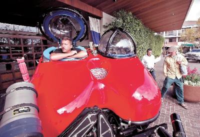
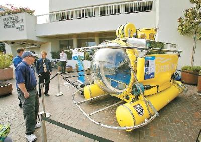
There's a yellow submarine sitting outside the Portola Hotel & Spa in Monterey. Another sub, a two-seater, is next to the front doors and two more manned underwater vessels are parked in the lobby. These diving machines are visiting Monterey as part of this week's BLUE Ocean Film Festival & Conservation Summit. Used for deep sea exploration, scientific research or just cruising under the ocean, these vessels have traveled the world, taking passengers as deep as 2,000 feet for up to eight hours. "This is a working sub," said Joe Lepore, a former Navy diver, referring to the red, two-man underwater vehicle that he pilots. The sub is owned by the Waitt Institute of Discovery in La Jolla. He drives the machine with foot pedals and calls the claustrophobic-looking seating arrangement "comfortable" because the bubble top seats have a 360-degree view. His passengers are scientists who want to collect samples, shoot video or map new underwater territory. The canary yellow sub called Antipodes is a party boat. Once used for tourist diving adventures, the vessel has bench-style seating for five. Owned by OceanGate, an ocean exploration company, it is part of the BLUE outreach program and will be traveling under Monterey Bay this week, taking students and other guests to local water spots such as the Art Riedel Sr. wreck and The Barge. This is a repeat visit for Antipodes, which took out local middle school students last fall. The manned underwater vehicles displayed in the hotel lobby look more like flying machines. The Super Falcon has a streamlined build with wings like a glider and cockpit style seating for two. "It's like taking a plane instead of an elevator," said Jay Tustin, pilot and technician for the Hawkes Ocean Technologies vehicle. Also in the lobby is Virgin Oceanic DeepFlight Challenger, which looks like it could be the next space shuttle prototype.
Iran Gets 'Serious' With Naval Expansion.
WASHINGTON: Iran's three new mini submarines could be Tehran's first real step toward expanding its naval presence, but the regional powerhouse is still a long way from being a legitimate threat to the United States or its allies, according to one defense analyst. Iranian naval officials last week unveiled the new Ghadir-class mini submarines they say will be used for defensive operations along their coast. The new boats brings the total number of Ghadir-class subs in the Iranian fleet to 14, the official Iranian news agency IRNA reported. The boats "lack the firepower to be used as a platform that projects meaningful naval power," according to Jonathan Rue, a defense analyst with the Washington-based defense think tank Institute for the Study of War. But the addition of the new mini subs represents the country's first real step toward building a formidable naval power, he added. "The new Ghadir sub deliveries are a sign that Iran is serious about upgrading its naval forces and using those forces to project its influence and expand its areas of operation," according to Rue. Before Iran can begin building a fleet that can go from the Indian Ocean to the Straits of Malacca, it must be able to defend its own shorelines, he explained. By bolstering the Ghadir-class of subs Tehran is doing just that, Rue said. Once its territorial waters are secure Iran can start building the ships that will push its naval presence forward. In an October report drafted by Rue and U.S. Navy Cmdr. Joshua Himes, the Iranian navy already has carried out missions as far as the Red Sea and the eastern edge of the Mediterranean Sea with its fleet of small, fast-attack vessels and Soviet-era Kilo attack subs. Iran's maritime plans -- which include new warships, ballistic anti-ship missiles and possibly a new aircraft carrier -- could force the U.S. Navy to pour more money and manpower into operations to contain that bolstered force. But Washington still has plenty of time before it will really have to worry about that, Rue said. "The gap between Iran's navy and the US Navy is so large that Iran is decades away from reaching a point of near parity," Rue said. The more immediate threat from Iran's naval expansion will be felt by American allies in the Persian Gulf, he said. Countries like Saudi Arabia and others are already bolstering their naval forces to counter the potential Iranian threat, with help from their American counterparts.The U.S. Navy's Fifth Fleet will continue to maintain a strong presence in the region despite the service's growing focus on the Western Pacific, Rue noted. "So a rising Iranian navy, while a concern and a growing menace, is not in a position to deny US access to international waters in the Persian Gulf or anywhere else."
Kursk’s sister ship returns to service.
The nuclear-powered Oscar-II class submarine “Voronezh” ready for mission again after five years of repair. The “Voronezh” submarine has just returned to Severodvinsk after sea trails following a long-lasting repair period at the Zvezdockha yard. The nuclear powered submarine is similar to the ill-fated "Kursk" that tragically sank in the Barents Sea in August 2000. “Voronezh” was taken to the Zvezdockha submarine yard in October 2006 for emergency repairs of the main turbine and to change the uranium fuel from her two reactors. In May 2009, the submarine was launched to sea again from the dock to complete the repairs afloat, a work that was supposed to be completed during 2009 BarentsObserver reported with reference to Vladimir Nikitin, General Director of Zvezdockha. Itar-Tass reports today that “Voronezh” will be transferred to the Northern fleet for active service again during November. Following the repairs, the submarine will have an extended service life of 3,5 years. The Oscar-II class is a multi-purpose submarine carrying cruise-missiles. They have their homeport on the Kola Peninsula, west of Murmansk
US Military Scientists are Working on Unmanned Long-Endurance Submarine.
US military scientists are developing an unmanned submarine that can hang around underwater for several months to track the presence of enemy submarines.
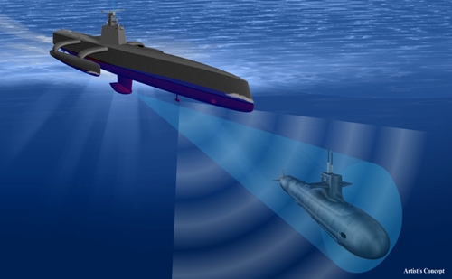
DARPA, the US Defense Advanced Research and Projects Agency, awarded a contract to the Science Applications International Corporation (SAIC) to develop the design, which is meant for the products of the ASW (Anti-Submarine Warfare) ACTUV (Continuous Trail Unmanned Vessel) program to offset the diesel-electric submarines, which are a potential risk to the US Navy and its global allies. SAIC is engaged in Phases 2, 3 and 4 of the ACTUV submarine program to design, develop, and conduct sea trials of an unmanned vessel that is capable of tracking diesel electric submarines, covering thousands of kilometers of sea with reduced man power. Particularly, Phase 2 is the ‘Design a vessel' stage and Phase 3 is the ‘Build a vessel' stage, while Phase 3 is the ‘Test a vessel' stage. Phase 1, which dealt with the refinement and validation of the system concept, is already completed. If successful, the ACTUV submarine program will deliver a superior technology to the US Navy and reduce the navy’s manpower expenses in addition to other benefits. Operational unmanned submarine sea trials are slated to commence between the second quarter and third quarter of 2015. DARPA's ACTUV program manager, Scott Littlefield stated that the vessel will feature robust autonomy ensuring safe operations according to maritime laws, advanced software, and advanced sensors to constantly track enemy submarines. In addition, the program creates foundational technologies for upcoming unmanned naval systems.
Navy: New investigations into suspect purchase of submarines.
Portuguese criminal investigation agency DCIAP announced it is to launch a probe into the purchase of two submarines from Germany for the Portuguese Navy in 2004 which has been clouded by suspicions of graft. Portuguese authorities will carry out new investigations into the purchase of two submarines from Germany for the Portuguese Navy in 2004 which has been clouded by suspicions of graft, the criminal investigation agency DCIAP said Wednesday, 22 August. The agency said in a press release that it would request the cooperation of the current and immediate past defence ministers, adding that “historic” documents related to the submarines’ public tender, contract signing, defence offset agreements, and financing remained “missing”. The minister of defence at the time of the purchase, current Minister for Foreign Affairs Paulo Portas, the leader of the coalition government’s junior partner, dismissed media reports earlier this month of missing documentation. Such reports, Portas said at the time, “emerge when it’s convenient and submerge when they’re no longer of interest”. Minister of Defence José Pedro Aguiar-Branco recently said he was unaware of any documentation missing from his ministry, but affirmed his readiness for “total collaboration” with the investigation.
Lost Submarine HMS Olympus discovered outside Malta
A marine archaeology survey team from the AURORA Trust Foundation, working in cooperation with Malta’s Superintendence of Cultural Heritage, has discovered the sunken British submarine HMS Olympus (N35) off the coast of Malta. AURORA’s Director of Marine Archeology, Dr. Timmy Gambin led the survey team in this spectacular discovery. The Olympus struck a mine on May 8, 1942 while leaving the British naval base in the Grand Harbor of Malta, and its location has remained a mystery for almost 70 years until its discovery by AURORA. In addition to its normal crew of 55, the Olympus was carrying 43 crewmen from two other British submarines that had been sunk during air raids by Italian and German forces. Leaving the Grand Harbor under cover of darkness, the Olympus was maneuvering to clear Malta and set a course for Gibraltar as its when it struck a mine and rapidly sank. Only 9 survivors of the 98 crew and passengers onboard made the 7-mile swim back to Malta, as the British forces were probably not immediately aware of the tragedy. The Olympus was an Odin class submarine launched in 1927. She served the Royal Australian Navy in China before being repositioned to the Mediterranean to support allied efforts against Italian and German shipping during WW II. The submarine is 283 feet (86.5m) in length and has a beam of just over 19 feet (6m). It has the distinctive deck gun and 8 bow torpedo tubes of the class. Craig Mullen, an AURORA Founder indicates it is sitting upright, almost as though it was still operational and ready to resume its voyage instead of immobile where it came to rest after the violence that brought it to its 70 year resting place on the seafloor off the coast of Malta. The mine damage is clearly visible in images collected by the ROV deployed by the AURORA team. The entire wreck site was thoroughly documented to confirm the wreck’s identity. The wreck though covered in sea growth and home to numerous sea life is in surprisingly good condition, and its distinctive features are clearly visible. The 4” deck gun is slightly elevated and ready for action and the bow and stern torpedo tubes are clearly identifiable in the wreck.
Repairs on fire-damage sub could take a year.
President Medvedev instructs to take all measures to restore the submarine. That job will take at least one year says the shipyard that does complex overhauling of Russia’s strategic nuclear powered submarines. As the metal in the front bow of the submarine “Yekaterinburg” is cooling after last week’s massive fire in the floating dock north of Murmansk, experts now start the assessments on the damage.

Firefighters cooling the hull of the submarine by pumping water on the front bow.
According to our first assessments, repairs may take as long as one year, says Yevgeny Gladyshev, spokesman for the Zvezdockha naval yard to RIA Novosti. He says the repair time will be known as soon as the extent of the damage is known and when it becomes clear whether the submarine’s hydro acoustic system needs to be replaced. Zvezdockha naval yard in Severodvinsk outside Arkhangelsk is the only yard in northwest Russia that does major repairs and overhaul of the Northern fleet’s larger nuclear powered submarines. The floating dock in Roslyakova north of Murmansk on the Kola Peninsula is normally only used for limited maintains on the hulls of submarines. Rubber on the outer hull in the front nose of the submarine was set on fire, likely caused by welding, on December 29th causing massive smoke and heat development as previously reported by BarentsObserver. Photos from the floating dock the day after shows firefighters pumping large amount of water on the hull and even inside one of the torpedo tubes to cool it down. President Dmitri Medvedev has instructed newly appointed Deputy Prime Minister Dmitry Rogozin to conduct a thorough investigation into the cause of the fire, the presidential portal reports. The investigation will be one of the first tasks for Dmitri Rogozin after returning home from the position as Russia’s high profiled envoy to NATO in Brussels. “Yekaterinburg” was scheduled for a larger so-called mid-life repair in 2013, according to a military source talking to Echo Moskva. If the repair need is so wide-ranging that the sub must be towed to Severodvinsk already now, it is likely that the larger overhaul will take place already this year
Russia To Begin Testing Kilo-Class Vietnamese Submarines.
Russian shipyard Admiralteiskie Verfi will soon begin testing a new Kilo-class Project 636 diesel-electric submarine for Vietnam. The shipyard on Tuesday launched the first of six submarines ordered by the Vietnamese government. The contract valued at $2 billion was signed in 2009. “The boat is due to be delivered to the customer by the end of the year. All six boats are due to be delivered by 2016,” a shipyard official was quoted as saying. Armed with 533-mm torpedo tubes and are armed with torpedos, mines, and Kaliber 3M54 (NATO SS-N-27) cruise missiles, the Project 636 class boats displace 3,100 tons, have a top speed of 20 knots and can dive to 300 meters with a crew of 52.
UAV launched from a submarine.
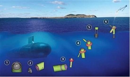
The military certainly does have their fair share of “big boys toys” to play around with, and the UAV (Unmanned Aerial Vehicle) is one of them – so here is one interesting idea that is worth looking into. While we know that most submarines are lurking underneath the seven seas, ready to launch a counterattack in the form of missiles on behalf of their countries, here is a novel idea – to launch UAVs from a submerged submarine. While this technology is still in its infancy, the Navy wants to toy around with it, attempting to perform a launch from periscope depth when they conduct exercises in the Pacific Ocean from 2012 onwards. Should the Navy’s plan fall into place, a Switchblade folding-wing drone will be ejected from the submarine’s trash disposal unit, where it will be carried to the surface by an SLV (Submerged Launch Vehicle) so that it remains dry, pointing it into the wind, followed by an almighty throw towards the heavens.
Personnel Shortage Places Britain’s Nuclear Deterrent at Risk.
Britain faces risk of losing its nuclear deterrent because of a lack of qualified personnel to man its submarines. According to a Ministry of Defense risk register report, the Royal Navy’s “inability to recruit, retain and develop” qualified manpower will cripple its Defense Nuclear Program. Officials admit that the country has not trained enough nuclear engineers. Nuclear engineers have become highly demanded by the civilian nuclear sector, and the navy is finding it difficult to attract new recruits. The report anticipates a 15 percent decrease in naval staff over the next three years. Even now, some vessels are being dispatched with only 85 percent of submariner staff capacity. “One in seven weapons officer posts ranked at lieutenant will also be vacant in the coming years, meaning there may not be enough people to fire weapons,” wrote the Mail Online. This staff shortage may leave the navy’s fleet of six attack submarines and four boats that carry the Trident nuclear missiles stranded in port. The Trident is Britain’s only nuclear weapon system in service. Former Royal Navy head Adml Lord West described the situation as “very worrying.” It could put Britain out of the “nuclear weapons business,” as Nuclear Information Service director, Peter Burt, noted. Disarmament activists may hail this development as positive. Our article “Disarmament Leads to War” explains otherwise.
The Japanese Navy included five Type - midget submarines in the Pearl Harbor raid of 7 December 1941.
Transported on board large I type submarines, the midgets were launched near the entrance to Pearl Harbor the night before the attack was to begin. One, spotted trying to enter the harbor before dawn, was attacked and sunk by USS Ward (DD-139) in the first combat action of the as yet unopened Pacific War. At least one of the midgets was able to enter the harbor and was sunk there by USS Monaghan (DD-354). Another, the Ha-19, unsuccessful in its attempts to penetrate Pearl Harbor, drifted around to the east coast of Oahu and was captured there the day after the attack.

The Trail of Corruption in The Case Karachi. The trail of a corruption scandal during the presidential campaign of 1995, may involve Nicolas Sarkozy, has been confirmed by court hearings, including that of a former minister. The case is linked to a suicide bombing in Karachi, May 8, 2002 in which 15 people died, including 11 French engineers and technicians from the Directorate of Naval Construction (DCN), working in the construction of submarines. Former Defence Minister Charles Millon (1995-1997) stated on record that Jacques Chirac ordered his election in 1995 after the termination of the payment of commissions pseudo-business in Pakistan in conjunction with the sale of these sub- sailors, “said a source close the file. “Charles Millon told the judge that the decision had been taken because of the existence of retro-commissions (fraudulent return of a portion of the money in France, Ed),” said the source who had access to the trial record of the hearing by the magistrate Renaud Van Ruymbeke. The track initially referred to the Islamist attack was abandoned and a variety of information, but no evidence suggests that the Pakistani army ordered the attack in retaliation for non-payment of remaining fees. Charles Millon told the Judge Van Ruymbeke that the DGSE – the French intelligence services – had been charged with a survey of retro-commissions and reported directly and orally to Jacques Chirac and Dominique de Villepin Secretary General. The Socialist opposition has responded by requesting a hearing of these two men. “Former President Chirac and Dominique de Villepin, who ended a device that they themselves had deemed illegal, must connect to justice the elements they have,” said in a statement Jean-Marc Ayrault, Chairman of the PS group in the National Assembly. President Francois Bayrou Modem has asked his side on France 2 the lifting of military secrecy, already partly achieved by the judge investigating the bombing Marc Trévidic. “This can not go on like this, we must rid the French politics of suspicion, he must raise the defence secret,” he said. Charles Millon had already mentioned these facts in the press when he told Paris Match this year it was discovered that the “retro-commissions” had financed the presidential campaign of Edouard Balladur, a rival to Jacques Chirac in the right the presidential race in 1995. Moreover, another witness heard by Judge Renaud Van Ruymbeke, Gerard Menai, former leader of the DCN, confirmed that the commission passed by Luxembourg, where two companies, Heine and Eurolux had been created for this purpose. This witness, the source familiar with the matter, confirming other elements of the court record, including a report from the Luxembourg police, according to which Nicolas Sarkozy, then Minister of Budget (1993-1995) and spokesperson of the campaign Balladur, had organized this transit in Luxembourg. Menai Gerard also said to Judge Van Ruymbeke that former leaders of Luxembourg companies in question attempted in 2006 to get money, to ’sing’ Nicolas Sarkozy on the basis of this case. A parliamentary fact-finding mission showed that the payment of 84 million euros, or 10.25% of the contract for submarines, had been agreed at the signing of the agreement for the sale of submarines by the government Balladur in 1994. Nicolas Sarkozy denies any involvement in a corruption case and spoke publicly of “fable” about the supposed link between money and attack.
Strategic Submarines
The future of Russia’s sea-based strategic deterrent force revolves around the Borei-class submarines, eight of which are planned to be built by 2017. The first was completed in 2008 and is currently undergoing sea trials. Another three are already under construction. While the submarines themselves seem to be in good shape, the project is currently mired in uncertainty because of continuing failures in testing of the Bulava SLBM with which they are to be equipped. The Bulava is the first solid-fuel SLBM to be used in Russian/Soviet submarines. The Bulava test missiles are being launched from the Dmitry Donskoy, the last of the Typhoon SSBNs, built in the late 1970s and modified a few years ago to launch the Bulava. Two other Typhoons are currently listed as inactive and may be modified in the future to carry conventional cruise missiles instead of SLBMs. The Russian Navy currently operates six Delta IV SSBNs, all based in the Northern Fleet. Four of the subs have already been upgraded to carry Sineva SLBMs. Two others are currently being overhauled, with expected relaunch dates in 2011 and 2012, respectively. The expectation is that these subs, which were all built in the late 1980s, will continue to serve through 2020-25. The Pacific Fleet currently has four active Delta III SSBNs, all built between 1979 and 1982. These subs carry the SS-N-18 SLBM. They are expected to be withdrawn from service in the near future, as the new Borei-class SSBNs enter the fleet. Original plans called for them to have been withdrawn already by 2010, but problems with the Bulava have so far prevented the Borei submarines from replacing the Delta IIIs. Assuming that the Bulava’s problems are resolved, 10-15 years from now, we are likely to see Russia maintaining a fleet of 12 SSBNs, most likely including 6-8 Boreis and 4-6 Delta IVs.
Multi-purpose Nuclear Submarines
The Russian Navy currently operates several kinds of multi-purpose submarines. The largest are the Oscar II class cruise missile submarines, built mostly in the 1980s and armed with P-700 Granit cruise missiles. Eight of these submarines are available to the navy, though at least three are currently in reserve or being repaired. As currently configured, their sole real purpose is to hunt down US carrier groups, though this is made difficult in practice by their large size and noisiness, characteristics that make them relatively easy to spot. In the future, they could be equipped with newer cruise missiles to expand their range of missions. Two more Oscar IIs were never completed but could be finished in the future, though it seems to me that this would not be a wise expenditure of limited procurement resources. The Akula is the main type of attack submarine currently in the Russian Navy. There are eight in active service, mostly in the Northern Fleet, though several more are being held in reserve. The older boats in this class are likely to be retired over the next decade. In addition, the Navy still operates four Victor III attack submarines and three Sierra I and II attack submarines. All of these are likely to be retired in the near future as well. The only replacement for these submarines, at the moment, is the Severdvinsk class, a modification of the Akula class that is considered by some experts to be the most sophisticated nuclear submarine in the world, able to travel at 33 knots, armed with 8 torpedo tubes and able to launch up to 24 cruise missiles simultaneously. They are similar in some ways to the American Sea Wolf submarine. At the same time, these submarines are very expensive and some analysts doubt the need for building too many of them given that the Sea Wolf program was cancelled after only three were built. For the moment, one submarine of this class has been launched and another is under construction. Navy officials have stated that they hope to start building one of these a year starting in 2011, but this seems highly unlikely given the financial constraints and technological limitations of Russian submarine building. It seems that this is the most problematic category for the Russian Navy’s submarine fleet. Ten years from now, the navy is likely to have at its disposal around 4 Oscar IIs, 4-5 Akulas, and no more than 3 Severdvinsk submarines. And the remaining Oscars and Akulas will have to be retired by 2025-2030. Given these numbers, what the navy desperately needs is a relatively basic, cheap, and easy to build attack submarine along the lines of the American Virginia class. While there are rumors that various bureaus are working on designs for such a submarine, there has been no official word on this process.
Diesel Submarines
The Russian Navy currently operates 12-15 Kilo class diesel-electric submarines, most of which were built in the 1980s. Several additional submarines are in reserve and a couple are under repair and will likely return to operational status. These are extremely quiet submarines, intended for anti-shipping and anti-submarine operations in shallow waters. They are armed with torpedoes and surface-to-air missiles. The successor to the Kilo is the Lada, the first of which (the St. Petersburg) was launched in 2005 but not commissioned until May 2010. Despite being listed in active service, the St. Petersburg continues to experience problems with its propulsion systems, which had been the cause of the delays in completing the sub’s sea trials. In the meantime, two other submarines of this class are under construction, though their completion is likely to be delayed until the problems with the St. Petersburg are resolved. The Russian navy hopes to build a total of eight Ladas by 2020, and more thereafter. Because of the urgent need for new diesel submarines in the Black Sea Fleet and the continuing problems with the Lada, in August 2010 the navy announced that it will build three improved Kilos (of a type previously built only for export) for the Black Sea Fleet. Construction of the first submarine has already begun and all three are expected to be completed by 2014. These are realistic timelines, given the speed with which these submarines have been built for the Chinese and Algerian navies.
Submarine hull
Modern submarines are usually cigar-shaped. This design, already visible on very early submarines (see below) is called a "teardrop hull", and was patterned after the bodies of whales. It significantly reduces the hydrodynamic drag on the sub when submerged, but decreases the sea-keeping capabilities and increases the drag while surfaced.
History
Since the limitations of the propulsion systems of early military submarines forced them to operate most their time on the surface, their hull designs were a compromise. Because of the slow submerged speeds of those subs, usually well below 10 kt, the increased drag for underwater travel was considered acceptable. Only late in World War II, when technology enhancements allowed faster and longer submerged operations and increased surveillance by enemy aircraft forced submarines to stay most of their times below the surface, did hull designs become teardrop shaped again, to reduce drag and noise. On modern military submarines the outer hull is covered with a thick layer of special sound-absorbing rubber, or anechoic plating, to make the submarine more difficult to detect by sonar.
Types
All small modern submarines and submersibles, as well as the oldest ones, have a single hull. However, for large submarines, the approaches have separated. All Soviet heavy submarines are built with a double hull structure, but American submarines usually are single-hulled. They still have light hull sections in bow and stern, which house main ballast tanks and provide hydrodynamically optimized shape, but the main, usually cylindrical, hull section has only a single plating layer.
Light hull
The double hull of a submarine is different from a ship's double hull. The external hull, which actually forms the shape of submarine, is called the outer hull or light hull. This term is especially appropriate for Russian submarine construction, where the light hull is usually made of steel that is only 2 to 4 millimeters thick, as it has the same pressure on both sides. The light hull can be used to mount equipment, which if attached directly to the pressure hull could cause unnecessary stress. The double hull approach also saves space inside the pressure hull, as the ring stiffeners and longitudinals can be located between the hulls. These measures help minimise the size of the pressure hull, which is much heavier than the light hull. Also, in case the submarine is damaged, the light hull takes some of the damage and does not compromise the boat's integrity, as long
Pressure hull
Inside the outer hull there is a strong hull, or pressure hull, which actually withstands the outside pressure and has normal atmospheric pressure inside. The pressure hull is generally constructed of thick high-strength steel with a complex structure and high strength reserve, and is separated with watertight bulkheads into several compartments. The pressure and light hulls aren't separated, and form a three-dimensional structure with increased strength. The interhull space is used for some of the equipment which doesn't require constant pressure to operate. The list significantly differs between submarines, and generally includes different water/air tanks. In case of a single-hull submarine, the light hull and the pressure hull are the same except for the bow and stern. The task of building a pressure hull is very difficult. No matter how large the submarine is, its hull must be constructed with very high precision. Inevitable minor deviations are resisted by the stiffener rings, but even a one inch (25 mm) deviation from roundness results in over 30 percent decrease of hydrostatic load.[1] The total pressure force of several million tons must be distributed evenly over the hull and be oriented longitudinally, as no material could resist such force by bending. A submarine hull has to use expensive transversal construction, with the stiffeners rings located more frequently than the longitudinals. All hull parts must be welded without defects, and all joints are checked several times with different methods. This contributes to very high cost of modern submarines (for instance, a Virginia class attack submarine costs 2.6 billion dollars, over $200,000 per ton of displacement).
Dive depth
The dive depth cannot be increased easily. Simply making the hull thicker increases the weight and requires reduction of the weight of onboard equipment, ultimately resulting in a bathyscaphe. This is affordable for civilian research submersibles, but not military submarines, so their dive depth was always bound by current technology. The World War One submarines had their hulls built of carbon steel, and could not submerge below 100 meters. During World War Two, high-strength alloyed steel was introduced, allowing for depths up to 200 meters. High-strength alloyed steel is still the main material for submarines today, with 250-350 meters depth limit, which cannot be exceeded on a military submarine without sacrificing other characteristics. To exceed that limit, a few submarines were built with titanium hulls. Titanium is stronger and lighter than steel, and is non-magnetic. Titanium submarines were especially favored by the Soviets, as they had developed specialized high-strength alloys, built an industry for producing titanium with affordable costs, and have several types of titanium submarines. Titanium alloys allow a major increase in depth, but other systems need to be redesigned as well, so test depth was limited to 1000 meters for K-278 Komsomolets, the deepest-diving military submarine. An Alfa class submarine may have successfully operated at 1300 meters,[2] though continuous operation at such depths would be an excessive stress for many submarine systems. Despite its benefits, high costs of titanium construction led to abandonment of titanium submarines idea as the Cold War ended.
Other types
There are examples of more than two hulls inside a submarine. The light hull of Typhoon class submarines houses two main pressure hulls, a smaller third pressure hull constituting most of the sail, two other for torpedoes and steering gear, and between the main hulls 20 MIRV SLBMs along with ballast tanks and some other systems. The Royal Netherlands Navy Dolfijn and Potvis class submarines housed three main pressure hulls.
Sea lions, dolphins serve as elite defence force
Boats with intimidating displays of weapons patrol the waters at the port at Kings Bay Naval Submarine Base. But if underwater intruders elude a patrol boat's sophisticated electronic surveillance, something else waits in the depths that Navy officials say cannot be fooled. For five years, 10 California sea lions and four Atlantic bottlenose dolphins have provided underwater security for Ohio-class submarines ported at Kings Bay as part of the Swimmer Interdiction Security System. Dolphins are trained to use their sophisticated sonar to detect unusual underwater activity and report it to their handlers. A dolphin is sent back to the area with a lighted beacon that it releases near the intruder to alert Navy security forces. "Their primary mission is finding an intruder and marking the target," project manager Steve Hugueley said. "These guys are really good about using sonar to find targets. They work at it every day." Sea lions are trained to carry a special cuff in their mouths that they can quickly clamp around an intruder's leg. "It's like a handcuff; it can only get tighter," Hugueley said. The intruder is reeled in by base security by a rope attached to the cuff, which can only be removed with a special key. "I think for bases who have these high-value assets, it's really a first line of defence for protection against underwater intruders," he said. Kings Bay is home to eight $2 billion Ohio-class submarines. Six of the boats carry ballistic nuclear missiles, while two were recently converted to carry cruise missiles. While the work is serious, the trainers and marine mammals in the program interact much like their counterparts at a tourist attraction such as SeaWorld. The animals are rewarded with a fish when they perform a task properly. One of the dolphins spun in the water with excitement when a trainer offered him a fish. During free time, connecting doors to pens are often opened so the animals can socialize with each other, Hugueley said. While trainers said teaching the animals is fun, the mission is serious. The marine mammal program, in existence since 1960, provided port security during the Vietnam War, protected the Third Fleet flagship overseeing Navy vessels that escorted Kuwaiti oil tankers in 1987 and performed port security in the Persian Gulf from 2003 to 2005. "It's the longest deployment elsewhere of any marine mammals, ever," said Tom LaPuzza, a spokesman for the Navy Marine Mammal Program. Though they are not native to the East Coast, environmental studies show sea lions have no adverse environmental impact at Kings Bay. The one concern before they arrived was how they would interact with manatees, but it appears the two species are indifferent to each other, Hugueley said. It takes about 18 months to train the animals in San Diego, where the Navy's marine mammal program is based, Hugueley said. "They actually take a test to make sure they know all the procedures," he said. LaPuzza said 80 bottlenose dolphins and 28 sea lions are available to perform underwater security at locations across the world. Currently they are only working at Kings Bay, but will soon be working at a Navy base in Bangor, Wash. "We saw they were easily trainable and reliable," LaPuzza said. "These animals can do a lot of things. A whole bunch of them do object recovery and mine hunting." Luckily, the marine mammals have only trained and have never had to respond to a threat on base, Hugueley said. Only dolphins bred in captivity and sea lions purchased from breeding programs at SeaWorld are used in the program. Handlers use a combination of divers and mannequins for training. The mannequins are used because they are more difficult to locate and they can be placed at any depth, Hugueley said.
The Ministry of Defence (MoD) has been accused of a “catalogue of blunders” after admitting there have been 16 crashes involving British nuclear-powered submarines since 1988.
More than half of the accidents were in seas around Scotland. According to critics, the repeated errors that caused the accidents suggest that the MoD has failed to learn from past mistakes. A serious incident in the future could cause radioactivity to leak and put public health at risk, they warn. The Royal Navy’s newest nuclear submarine, HMS Astute, is being repaired at the Faslane naval base on the Clyde after it ran aground for 10 hours near the Skye Bridge on October 22. It emerged last week that one of the boat’s fins was damaged in a collision with a tug trying to rescue it. The list of accidents came in a parliamentary answer to the Scottish Nationalist defence spokesman, Angus Robertson MP. In addition to HMS Astute last month, it included eight other accidents in Scottish waters. Two were around Skye, one near Lewis, and one in the Firth of Clyde. Another occurred in the North Channel off the south-west coast and two in unspecified places “west of Scotland”. The incident involving HMS Astute was clearly not a one-off, and the MoD must explain previous groundings. The worst incident was on November 22, 1990, when HMS Trenchant snagged the net of the Antares fishing vessel in Bute Sound, north of Arran. The boat sank with the loss of four lives, and an official inquiry blamed mistakes by submarine commanders. The list also revealed a previously unreported accident in April 2009 somewhere in the Eastern Mediterranean. “HMS Torbay grounded in soft sand and mud to avoid a merchant vessel which was sailing erratically,” an MoD spokeswoman told the Sunday Herald. The craft had not been damaged, she said. “The incident was investigated and no further action was taken.” Other incidents took place off the coast of Northern Ireland, in the north Norwegian Sea, in the Arctic, in the Red Sea, in the Atlantic, and off Australia. In all, Britain’s nuclear submarines have run aground 11 times, collided with two other boats and an iceberg, and snagged the nets of two fishing vessels. The incident involving HMS Astute was clearly not a one-off, and the MoD must explain why previous groundings have not been made public,” said Mr Robertson. “One collision is one too many – especially when it involves a submarine with a nuclear reactor. This catalogue of blunders makes the MoD look even more shambolic, and leaves the credibility of the nuclear deterrent in tatters.” An independent expert on nuclear submarine safety, John Large, argued that the number of accidents is increasing, and the possible hazards growing. He called on the Royal Navy to review its navigational training. “Collisions and groundings not only put the submarine hull at risk of damage but also put the weapons, both nuclear and conventional, and the nuclear reactor in jeopardy,” he said. “If any of these elements were damaged the consequences to submariners and the public at large could be severe.” The 120 or so crew on board are “wholly insufficient” to deal with a major leak of radioactivity, he claimed. The MoD defended its record, saying: “When incidents do occur, they are taken very seriously. Each is thoroughly investigated and lessons are learnt.” But John Ainslie, coordinator of the Scottish Campaign for Nuclear Disarmament, pointed out that detailed reports on submarine accidents are destroyed after 10 years. “This may explain why they repeat the same mistakes,” he said. “It is time the Royal Navy stopped treating the coast of Scotland as a playground for nuclear submarines.”
October 2010 HMS Astute grounded off the Isle of Skye
April 2009 HMS Torbay grounded in the Eastern Mediterranean
February 2009 HMS Vanguard collided with the French submarine Le Triomphant in the Atlantic
May 2008 HMS Superb grounded in the Red Sea
May 2003 HMS Tireless struck an iceberg while on Arctic Patrol
November 2002 HMS Trafalgar grounded on Fladda-Chuain, north of Skye
November 2000 HMS Triumph grounded west of Scotland
November 2000 HMS Victorious grounded on Skelmorlie Bank in the Firth of Clyde
July 1997 HMS Trenchant grounded off the coast of Australia
July 1996 HMS Repulse grounded in the North Channel off south-west Scotland
July 1996 HMS Trafalgar grounded off the Isle of Skye
March 1991 HMS Valiant grounded in the North Norwegian Sea
November 1990 HMS Trenchant snagged the fishing vessel Antares off Arran
October 1989 HMS Spartan grounded west of Scotland
November 1989 HMS Sceptre snagged the fishing vessel Scotia near Lewis
July 1988 HMS Conqueror collided with the yacht Dalriada off the coast of Northern Ireland
'Scandalous' submarine deal highlighted ahead of Nato summit
Leaders are heading to Lisbon for a summit on Friday (19 November) at a time of escalating economic problems in Portugal, due, in part, to a submarine deal, with corruption investigations launched both in Germany and Portugal into the way the deal was made. Unlike non-Nato Ireland, whose record public-deficit of over 30 percent is mostly due to bailing out banks in the wake of the financial crisis, the southern European country's accounts are also weighed down partly by a controversial submarine deal with Germany that dates back to 2004 but that has to be paid for now. Signed during at a time when current European Commission chief Jose Manuel Barroso was head of the Portuguese government, the deal worth €1billion is the biggest military purchase in the country's history. Payments for the two German submarines amount to 0.6 percent of the country's gross domestic product (GDP), at a time when the budget deficit reached of 9.3 percent of GDP last year. According to Portuguese Socialist MEP Ana Gomes, the country's current centre-left premier, Jose Socrates, has been "very vocal" in blaming the submarine purchase for the country's widening deficit and to justify the austerity measures that were adopted last month. With corruption investigations launched both in Germany and Portugal into the way the deal was made, Ms Gomes has called the deal "scandalous". What we don't see is political courage on the part of the EU institutions, notably the European Commission, to actually tackle this question of corruption that is at the root of the current crisis. Corruption in the management of banks, which were not properly regulated and supervised and corruption in the public sector in relation to defence procurements." With a similar submarine corruption probe involving the same German company (Man Ferrostaal) being investigated in relation to Greece, the first euro-area country that needed a bail-out, Ms Gomes said it is unacceptable that Brussels is not launching an inquiry into "this European web of corruption." The Portuguese MEP said she is "disappointed" that her government has not stood up to the German administration and frozen payments until the corruption case is finalised: "It would have been a courageous gesture to show that Portugal is a country whose people are victims of corrupt practices between German and Portuguese officials and companies."
HMS Astute submarine.
A nuclear-powered submarine has run aground off the coast of a Scottish island, the Ministry of Defence confirmed. The incident involving HMS Astute happened near the Isle of Skye. There were no reports of any injuries. A Ministry of Defence spokesman said: "We are aware of an incident involving one of our submarines off the Isle of Skye. This is a not a nuclear incident. "We are responding to the incident and can confirm that there are no injuries to personnel and the submarine remains watertight. There is no indication of any environmental impact." It is understood that the submarine's crew is waiting for high tide so they could free the vessel. In June 2007 the mammoth £3.5 billion nuclear-powered HMS Astute was named and launched by the Duchess of Cornwall. The submarine weighs 7,800 tonnes, equivalent to nearly 1,000 double-decker buses, and is almost 100 metres (328ft) long. Its Spearfish torpedoes and Tomahawk cruise missiles are capable of delivering pin-point strikes from 2,000km (1,240 miles) with conventional weapons.
The Indonesian Navy (TNI AL) needs 39 more submarines to protect the country`s vast marine territory against external threat.
"Indonesia needs to increase its naval fleet. We have vast marine territory which needs intensive security to protect it against external disturbance," Deputy Naval Chief of Staff Vice Admiral Marsetio said here on Wednesday. Vice Marshal Marsetio was in Bogor to attend a unit commanders roll call initiated by the Marine Corps. A total of 84 personnel from different command units at the Marine Corps took part in the event. He said the Indonesian Navy`s main armament system was still far from adequate. "Our main armament system needs to be increased and strengthened. We need to increase the number of submarines as we now only have a few units." As the world`s largest archipelagic country, Indonesia saw the urgency to have submarines in adequate numbers to protect its marine sovereignty, he said. "We need 39 more submarines," he said. The addition of the 39 submarines would hopefully help the Indonesian Navy keep the country`s marine territory intact, he said. "The submarines will be stationed in various parts of the country`s marine territory. We will give extra security particularly on outlying islands and waters prone to foreign countries` claim," he said. "We must keep the sovereignty and territory of the Unitary Republic of Indonesia intact. We will not let an inch of land go to foreign parties," he said.
Russia launched a nuclear-powered attack submarine that took 17 years to build because of funding shortages following the Soviet collapse.
President Dmitry Medvedev said the Severodvinsk should "increase our military might and our naval potential, and strengthen Russia's position in the world's oceans." "Russia simply must modernize its navy, we must build the most modern ships," Medvedev said at the ceremony at the Sevmash shipyard in the White Sea port that shares the vessel's name. Analysts said the launch of the Severodvinsk, the first in a new class of submarines, was a step in that direction, but cautioned that the vessel is not complete and still faces tests. "Putting it in water does not show that it is ready," said Konstantin Makiyenko, deputy director of the Moscow-based Centre for Analysis of Strategies and Technologies. Officials at the Sevmash said the submarine is 80 percent complete and that trials are to begin this summer, according to the Itar-Tass news agency. State-run RIA said the 119-metre (393-foot) Severodvinsk is the first Yasen/Graney class submarine, and is designed to carry long-range nuclear-capable cruise missiles and other armaments. RIA and Itar-Tass reported that the Severodvinsk is expected to enter service by 2011, but Makiyenko said that was "extremely optimistic." He said it might take three to five years. He also said it is unclear whether Russia will have the funding to produce several more submarines of the same class if the Severodvinsk is successful. Russian plans to build at least six of them, according to state-run RIA news agency. It said work began last year on the second submarine in the series, dubbed the Kazan. Construction of the Severodvinsk began in 1993, but Makiyenko said it was effectively frozen for about a decade because of funding shortfalls.
Navy gives new minisub a try After Northrop failure.
The Advanced SEAL Delivery System based in Hawaii was supposed to be the first in a fleet of high-tech minisubs that were to cost $80 million apiece, ride attached to a larger attack submarine, and deliver commandos undetected into harbours. Instead, the Northrop Grumman effort spiralled to more than $885 million, with only one sub built. A November 2008 fire as a minisub's batteries were recharging provided the death knell to the troubled program. But where others saw embarrassing failure, Brett Phaneuf saw commercial opportunity. Phaneuf's company, Submergence Group LLC, which builds experimental submarines, thought it could build a better mousetrap, or at least a more economical minisub for Navy use. "We were told that it couldn't be done and it would cost hundreds of millions of dollars and we thought, 'Well, how hard can it be?' " he said. "So we decided to take a shot at it with our own money to try to see if we could crack it." Development took two years. The Navy liked what it saw, according to Phaneuf, president of Submergence Group, based in Chester, Conn. His 25-foot-long S301 mini-sub was moved last fall to Navy SEAL Delivery Vehicle Team One's facility on the Pearl City Peninsula, where the hulk of the much costlier Advanced SEAL Delivery System sub still resides. Development and production of the S301, capable of transporting two pilots and six divers, cost less than $10 million, Phaneuf said. He emphasized that the minisub is no replacement for the much larger and more complex ASDS, but it shows what's possible. Essentially, what it is, is a technology demonstrator, to show that a small submarine could be built ... that would fit inside a dry deck shelter on a host submarine," Phaneuf said. The minisub arrived as a demonstration project, but a federal notice posted Feb. 9 signalled the Navy's intent to lease the S301 for use in Hawai'i for up to a year longer. In the meantime, Submergence Group said that in several weeks it will move another of its subs, a 30-footer called the S201 that can dive to 1,000 feet, to Pearl City. Enough of Submergence Group's efforts are now being devoted to Hawai'i that Phaneuf closed its operations center in Virginia City, Va., and moved some of the staff to Pearl City Peninsula and will be hiring a few more. U.S. Special Operations Command at MacDill Air Force Base in Florida said in an e-mail that "knowledge gained from this lease will lower overall risk and program costs of future undersea mobility acquisition programs. Additionally, the S301 is a civilian submersible whose performance will be evaluated in order to determine the most economic and operationally sound way ahead for Naval Special Warfare short-range submersibles."
In the wake of the ASDS problems, Special Operations Command is pursuing development of a Shallow Water Combat Submersible, a SEAL transport vehicle that would be launched from dry deck shelters mounted on larger attack submarines and require the use of scuba gear. Dry deck shelters are 38-foot removable compartments that allow SEALs access to the watertight module from a submarine via a hatch. Once SEALs are in the vehicle, the shelter is flooded and a hatch is opened, allowing the vehicle to exit while underwater. One of the reasons for the development of the ASDS minisub was to keep SEALs in a dry environment prior to a mission rather than expose them to the energy-sapping ocean cold for long periods in the SEAL Delivery Vehicle.
A 2009 federal notice for the development of the replacement Shallow Water Combat Submersible said the vehicle must be capable of transporting SEALs for up to 12 hours while they breathe from scuba gear. Naval analyst and author Norman Polmar said he thinks the Navy eventually has to again go the minisub route for SEAL insertion. "I would say yes, because you really want a system that you can put on a submarine, take 2,000 miles, and have it clandestinely launch from the submarine and take four or six guys into a harbor or somewhere," Polmar said. A new $47 million compound for SEAL Delivery Vehicle Team One was completed in 2004 at Pearl City Peninsula with facilities for the 65-foot-long ASDS sub. At the time, the facility housed five Mark 8 Mod 1 SEAL Delivery Vehicles and three dry deck shelters, the Navy said. The Navy has two SEAL Delivery Vehicle teams. Special Operations Command said the Hawai'i unit has about 300 officers, enlisted members and civilians who are a mix of SEALs, combat support sailors and technicians. Phaneuf said the S301 minisub was built to civilian American Bureau of Shipping standards and not Navy requirements because a civilian research use might be found in the future. The 13-ton minisub can operate at greater than 600 feet, according to the company, and "lock out," or allow divers to enter the sea while submerged. It is powered by lithium ion batteries. Because the minisub is made to civilian standards, Submergence Group employees and not Navy divers operate it in tests in Pearl Harbor, Phaneuf said. The sub also is not used for testing in dry deck shelters on attack submarines, but Phaneuf said the S301 would fit inside, and he's having a dry deck shelter simulator fabricated to do underwater testing with the minisub. Phaneuf said the S301 testing is an opportunity for the Navy to learn how the commercial sector builds submarines. "It's a really good partnership because the government didn't have to spend a nickel to get this thing built," he said.
North Korea cease all military co-operation with South Korea
In addition, the main headquarters of the Korean People’s Army informed the South Korean armed forces that the DPRK immediately strike if South Korean ships violate maritime border between the two Koreas in the Yellow Sea. Regular statements by North Korea comes amid escalating crisis in the inter-Korean relationship associated with the death of South Korean corvette “Cheonan. The experts who prepared a report on the incident, agreed that the ship sank after it was torpedoed by a North Korean submarine. At the same time the statement the DPRK official news agency says that shooting, Cheonan, has been profitable the U.S. to increase tensions between North and South, Pyongyang is not got no benefit from this incident. North Korea has never needed the world to the year 2012 to reach the planned prosperity, explain its power. Property of the South Korean version of the death of the ship is and with Russia. In this regard, the navy sent its representatives to Seoul to place to get acquainted with the outcome of the investigation. Two submarines, the DPRK returned to their base radio station Ekho Moskvy, referring to South Korean media. Previously reported Most – from 70% to 80% – of North Korean submarines are based along the east coast. Great depth to create a submarine North Korea “a haven,” said South Korean newspaper The Chosun Ilbo. North Korea has about 70 submarines – 20 class submarines “Romeo” and 1800 m, 40 – Class “Shark” (325 m) and 10 – classes, “Salmon” (130 tons). It is one of the last suspects Commission torpedo sank the corvette Cheonan. On the east coast of the DPRK are four submarine base. The largest of these databases – and Chaho Mayangdo. With the base Chaho and disappeared four class submarines “Shark.” Small submarines, North Korea, apparently, even with the 90-ies regularly enter the water areas of South Korea. Entries found on board captured the 1998 North Korean submarine indicates the number of such crossings. Naval Command in South Korea has deployed anti-submarine ships, corvettes and other boats to search for the disappeared from radar screens of North Korean submarines.
Japan to Beef Up Submarines to Counter Chinese Power
Japan is to increase its submarine fleet for the first time in 36 years, the Sankei Shimbun reported Sunday. The plan apparently aims to counter China's naval build-up by partially filling the void created by the U.S. reduction of submarines in the Pacific area. The paper said the Japanese government plans to increase the number of submarines from the current 18 including two trainer submarines to more than 20 when it revises its Defence Program Guidelines by year's end. Tokyo has maintained 18 submarines since it first formulated the guidelines in 1976, although it has strengthened their capability by replacing superannuated vessels and with new ones. Japan's new class of diesel-powered Soryu submarines But now that advanced technology gives them a longer lifespan, it has opted for the new plan to increase the total number, the daily reported. Exactly how many the country will have is not known. Even more than 20 is no match for China, which has 62, but experts say most of the Japanese submarines are new types with superior capability. The immediate cause for the decision was apparently China's plan to build an oceangoing fleet. China declared the plan at a fleet review in Qingdao, Shandong Province in April. It envisions extending its area of operations to the Pacific and Indian Oceans. Out of the 62 Chinese submarines, seven are nuclear-powered and 55 diesel-powered. China recently built an underground submarine base on Hainan Island, which overlooks the South China Sea.
Military Increasingly Convinced of N.Korean Sub Attack.
Military officials and experts believe that if a North Korean torpedo was involved in the sinking of the South Korean Navy corvette Cheonan, it was probably launched from a 325-ton Shark-class submarine. The sub ranks between a full-blown submarine and a mini-sub in terms of size. South Korean military intelligence are reportedly focusing on the fact that one or two Shark-class submarines from a submarine base in Cape Bipagot, South Hwanghae Province are unaccounted for during the time of the Cheonanâ sinking. The Bipagot submarine base is around 80 km from Baeknyeong Island. Shark-class submarines can travel at speeds of 13 km/h under water, so it would take them between six and seven hours to reach Baeknyeong Island. Intelligence officers and experts believe the sub made the trip under water, since travelling on the surface of the water would have exposed it to South Korean and U.S. spy planes and surveillance satellites. A drawback of the Shark-class diesel-powered submarines is that they need to surface regularly to recharge their batteries and ventilate, a process known as snorkelling. during this process, the ventilation device can be detected by radar and other surveillance equipment. The snorkeling equipment is not big, so there is a slim chance that it was detected by South Korean radars while the sub was in North Korean waters, said one source. The military believes a North Korean sub could have approached by taking a detour through open seas left of Baeknyeong Island, instead of coming in straight between Hwanghae Province and Baeknyeong Island. That is because the underwater currents are extremely fast in that area and it is closely monitored by South Korean forces. There is also the possibility that a sub could have drifted into waters near Baeknyeong Island with its engines shut off. Between 3 p.m. and 9 p.m. on March 26, the day the Cheonan sank, the currents flowed north to south and shifted direction from south to north after 9:40 p.m., said military expert Kim Byung-ki. There is the possibility that a North Korean sub was lying in wait and used the northerly current to return to North Korea after the attack. Once it infiltrated waters near Baeknyeong Island, it could have fired a torpedo around 1 km to 2 km away from the Cheonan in deeper waters. and a mid-sized torpedo, weighing more than 200 kg rather than a small one weighing between 50 kg to 80 kg, is being cited as the probable weapon, judging from the huge damage the Cheonan suffered. A lingering question is why the Cheonanâ radar system was unable to detect a torpedo attack, if that was indeed the cause of the sinking. The Defence Ministry says the sonar aboard a South Korean warship like the Cheonan has a 70-percent chance of detecting submarines or semi-submersibles around a 2 km radius. But retired naval commanders say the chances are actually only 50 percent, so sonar officers could have been unaware of an approaching torpedo.
Turkey, with help from Germany, to become 'submarine manufacturer'
ANKARA — Turkey has launched a project to produce an advanced naval submarine. Turkey's Defence Ministry and Navy have been working with Germany in the co production of four electric-diesel submarines. The co production effort has taken place with Germany's ThyssenKrupp for the Type 214 submarine. "This is a huge project that will make Turkey into a submarine manufacturer," an official said.
KILO Submarines.
Russia sees a growth market for its Kilo class diesel electric submarines, a 30-year-old design that first entered service in 1982. So far, 49 have been built, 42 are still in service and six are under construction. Russia sees foreign markets that need at least another 36 Kilos. It may be an old design, but it is mature and has been updated with modern electronics and quieting technology (that makes it more difficult to detect under water.) The Kilos weigh 2,300 tons (surface displacement), have six torpedo tubes and a crew of 52. They can travel about 700 kilometers under water at a quiet speed of about five kilometers an hour. Top speed underwater is 32 kilometers an hour. Kilos carry 18 torpedoes or SS-N-27 anti-ship missiles (with a range of 300 kilometers and launched underwater from the torpedo tubes.) Kilos can stay at sea 45 days at a time. It can travel at periscope depth (using a snorkel device to bring in air) for 12,000 kilometers at 12 kilometers an hour. The combination of quietness and cruise missiles makes Kilo very dangerous to American carriers. North Korea, China, India, Indonesia, Romania, Algeria, Vietnam and Iran have also bought Kilos. The main reason for purchasing Kilos is that they cost about half what equivalent Western subs go for. The biggest potential competitor for Kilo is China, which shamelessly copies Russian military designs. The Chinese Type 39A, or Song class, looks just like the Russian Kilo. This all began in the 1990s, when the Chinese began ordering Russian Kilo class subs, then one of the latest diesel-electric design available. Russia was selling new Kilos for about $200 million each, which was about half the price other Western nations sold similar boats. Then the Chinese built two Songs, the second one an improvement on the first. These two boats have been at sea to try out the technology that was pilfered from the Russians. A third Song was built, and appears to be a bit different from the first two. The first Song appeared to be a copy of the early model Kilo (the model 877), while the second Song appeared to copy the late Kilos (model 636). The third Song boat appears to be a further evolution. Russia has warned China of trying to export these copies, in competition with the Russian originals.
Jin SSBN Flashes its Tubes
One of China’s two new Jin-class SSBNs was photographed with two of 12 missile tubes open when it visited Xiaopingdao Naval Base in March 2009. The Jins are being readied to carry the JL-2, a single-warhead regional sea-launched ballistic missile that was most recently test-launched in May 2008. The class may become operational soon and replace the old Xia from 1982. Xiaopingdao Naval Base, which is where I identified the Jin-class for the first time in 2007, serves as an outfitting and testing facility for new submarines and used to be the homeport of the single Golf-class diesel submarine China used for many years as a test launch platform for its first ballistic missile. Two or three Jin-class SSBN have been under construction, and it remains to be seen if China will build up to five as projected by U.S. intelligence. China’s nuclear submarines appear to be the noisiest nuclear submarines in the world and will probably be highly vulnerable at sea. The U.S. Office of Naval Intelligence described in August 2009 that two of China’s SSBNs (probably one Jin and the Xia) were based at the Northern Fleet Base in Jianggezhuang, and the third boat (probably the second Jin) at the Southern Fleet Base on Hainan Island. I identified the Jin at Hainan in February 2008
Pakistan Navy Interested in Sang-O Class Submarine?
Name: Sang-O
Operators: Democratic People's Republic of Korea (North Korea)
Subclasses: Attack version + Infiltration + Reconnaissance
Service: Active
Displacement: 370 tons (submerged)
Length: 34m
Beam: 3.8m
Propulsion: Diesel-electric: 1 small diesel, 1 electric motor, 1 shaft
Speed: 7.5 knots (13.9 km/h) surfaced
7 knots (13 km/h) snorkeling
9 knots (17 km/h) submerged
Range: 1,500 nautical miles (2,800 km)
Test depth: 150 metres, capable of bottoming
Capacity: 0 (10/11 in recce version)
Complement: 15 crew
Sensors: Radar
Processing: Civilian Furuno I-band radar
Systems: Passive RWR/ESM/SIGINT Golf Ball radar & Snoop Plate radar
Sonar: Trout Cheek sonar
Armament: Two 21 inches (530 mm) torpedo tubes fitted with Russian 53-65KE torpedoes
capable of minelaying
Notes: Fitted with a snorkel
The Sang-O class submarines are currently in use by North Korea, and are the country's largest home-built submarines units.
Iran navy equipped with four new submarines
TEHRAN — Iran's navy on Sunday took delivery of four new mini submarines of the home-produced Ghadir class, media reports said. The navy already owns seven submarines of this type which weigh 120 tonnes and were first launched in 2007.Iran has described the Ghadir as stealth submarines, hardly detectable by sonar and aimed at coastal operations in shallow waters, notably in the Gulf. The vessel is based on North Korean models of the Yono class and can shoot torpedoes, but their main tasks appear to be moving commandos, laying mines and reconnaissance missions, experts say. Iran's inventory of submarines patrolling Gulf waters also includes up to three Russian-built Kilo class diesel submarines bought in 1990s and a Nahang, an Iranian-built light sub weighing 500 tonnes that was first launched in 2006. In 2008 Iran started building a new submarine named Qaem which is due to be launched within days, Iran's army chief Ataollah Salehi said last week, describing it as "semi-heavy" and capable of operating in the high seas such as the Indian Ocean or the Gulf of Aden. Little information has been released about this home-produced vessel, which is said to be capable of firing missiles and torpedoes.
SOUTH AMERICAN NAVAL POWER
ARGENTINA
At the Almirante Storni Shipyard in Buenos Aires on the 22nd January, the hull of Type TR-1700 submarine ARA “San Juan” was cut open to facilitate replacement of diesel generators. With this act the Argentine navy has recovered a technological capability lost since the 90s when the then Astilleros Domecq Garcia Shipyard was closed and deactivated. The shipyard was re-opened in 2003 and since then a number of technological capabilities have been restored, including the recovery of battery units, providing a firm base for the local integral overhauling, maintenance
and construction of submarines. Project PAM (Patrulleros de Alta Mar) is for up to 5 OPVs of 1,800 tons. With a length of over 80m, the ships are to have diesel propulsion and to be armed with a 40mm gun. The ships will be built at the Rio Santiago shipyard to the same Fassmer design as the Chilean boats with construction expected to begin in 2009.
BRAZIL
An official confirmation of plans to acquire four diesel electric submarines, built to a design derived from the SCORPENE licensed from DCNS, came in December 2008. Three conventional boats will be built at a new shipyard to be constructed by local engineering firm Odebretch at Itaguai, 500km south of Rio de Janeiro. The new shipyard will be known as Arsenal de Sepetiba and will include a new home base for the Submarine Force, set to move from its current site at Naval Base Almirante Castro e Silva, at the Bay of Guanabara, close to Rio de Janeiro. DCNS will build the lead of the series at its Cherbourg Shipyards. The total cost of the project, including the construction and fitting of the shipyard and the building of four submarines, is said to be in the area of US$4Bn. According to local sources, work towards the nuclear submarine during the last three decades had accumulated US$1.1Bn by by 2006. To date, the official line is that an additional budget allocation of no less than US$1.5Bn will be needed, in order to facilitate construction of a first nuclear powered submarine by 2020.
However, many observers believe that current financial and schedule expectations surrounding the project are over-optimistic – year 2030 would be a more realistic deadline to see a Brazilian nuclear powered submarine going to sea, if a budget close to US$2.5Bn is secured.
The main role of the Navy, according to the New Defence Strategic Plan is to provide security to the new oil and gas fields of TUPI and JUPITER off the coast of Rio de Janeiro. Despite the financial constraints during recent years, the Brazilian Navy deploys the largest fleet in South America. Regarding amphibious capabilities, the single “Newport” class LST “Mattoso Maia” and both “Thomaston” class LPDs “Ceara” and “Rio de Janeiro” were re-inforced between 2007 and 2008 with the acquisition of the ex-Sir Galand 2008 re-named “Garcia D’Avila” and ex-Sir Bedivere renamed “Almirante Saboia,” both joining the fleet in Brazil after completing a refit in Falmouth in July 2009. In 2005, the six “Niteroi” class frigates completed the MOD-FRAG refit programme, receiving a complete upgrade of their combat systems. According to reports, plans exist to replace them during the next decade by six FREMM multipurpose frigates equipped with cruise missiles and a long range air defence system. In September 2006 the Brazilian Navy ordered two NAPA 500-class offshore patrol vessels (OPVs) based on the Vigilante 400 CL 54 design from French shipbuilder CMN Group. Displacing 477 tons the ships are being built locally at Brazil’s INACE (Industria Naval do Ceara SA) yard at Fortaleza and were due for delivery in 2009. A further 4 OPVs have been approved, with a total of eight ships planned. The aircraft carrier “Sao Paulo” is the only vessel of this kind in service in South America. Recent reports about plans to acquire and modify some S-2 aircraft for ASW and AEW roles, as well as to upgrade the AF-1 SKYHAWK jet fighter bombers or a guided weapons capability including anti-ship missiles, indicate intentions todevelop the potential of this ship. Brazil is on its way to deploy a fleet including an impressive submarine force by the end of the next decade. It will be made up of nine modern and capable diesel electric boats, including the “Tupi” and “Tikuna” class, which are going to be fitted with a new combat system provided by Lockheed Martin and Mk48 heavyweight torpedoes.
CHILE
On 15th October 2008, Chile’s government-owned shipyard Astilleros y Maestranzas de la Armada (ASMAR) launched the second of 4 patrulleros de zona maritime (PZM) OPVs under the Chilean Navy’s Danubio IV project. The 1,850 ton boats are destined to patrol Chile’s extensive Pacific and Antarctic waters providing protection in the EEZ and a SAR capability. The 80m PZMs are powered by Wartsila engines to give a speed of 20kt and a range of 8,600nm. Armaments consist of a 40mm naval gun and machine guns. The ships can support a 322C Cougar helicopter and two 7m rigid inflatable boats (RIB). The first ship, Piloto Pardo, was commissioned in June 2008 with the second ship, Policarpo Toro, due to handover in early 2009.
COLOMBIA
2 OPVs are reportedly being built for delivery in 2010.
ECUADOR
Plans to acquire 1 OPV. Modernisation of both Type 209 Submarines is planned. Replacement of the 2 Leander Class Frigates is reportedly under consideration.
MEXICO
2 Oaxaca class OPVs are being built, for commissioning in 2010. A further 2 are planned.
PERU
Replacement of the Submarine Flotilla is under consideration. Up to 3 LSLs are planned.
URUGUAY
Plans to acquire 1 OPV.
VENEZUELA
Navantia is building four 2,400 ton POVZEE (Patrullero Oceanico para la Vigilancia de la Zona Economica Exclusiva) OPVs for the Venezuelan Navy at its Puerto Real shipyard near Cadiz. Construction commenced on the 11th September 2008 with deliveries expected in 2010-11. They will carry out patrolling tasks in Venezuela’s EEZ. They will eventually be accompanied by four 76m, 1500 ton Buque de Vigilancia de Litoral (BVL) coastal patrol ships that Navantia is building for Venezuela at its San Fernando yard. The first vessel, Guaicamacuto, was launched on the 16th October 2008 and will commission in 2009 with the remainder to be
delivered by 2011. Acquisition of 3 new submarines is reportedly under consideration.
Indian Navy Sees Midget Submarines as Primary Threat
NEW DELHI --- The Indian Navy and Coast Guard believe that improvised mini-submarines constitute the nation's primary emerging threat. These may range from swimmer-delivery vehicles of the type employed for recreational scuba diving to remotely operated vehicles and autonomous underwater vehicles. These types of vehicles are already in service with the navies of Iran, Myanmar and Pakistan (all having procured them from North Korea). As has been amply demonstrated by the navies of North Korea and Iran, these small vessels make good platforms for ambushes even at submerged depths of 150 feet, enough room for the midget submersible to maneuver. These submarines cannot travel too far on their own, and depend on support vessels to extend their range. However, in their shallow water element where sonar returns are cluttered, they can prove quiet and deadly. Their capabilities include the ability to lay mines or insert commandos on beaches. As North Korea demonstrated with the sinking of the Cheonan, attacks from midget submersibles can also include torpedoes armed with 250-kilogram warheads. The Indian Navy believes that two factors heighten the risk of an ambush by midget submarines against Indian warships. These are the complex sonar picture of shallow water where these small submersibles can operate, and the absence of a network of seabed-mounted sonar transducers dotting the Indian coastline. With the exception of Port Blair, none of the 200 non-major ports in India are equipped with any identification or surveillance systems, and there are currently no concrete ground rules for patrolling India’s inshore coastal areas and the numerous creeks and rivulets along the coastline. In early 2009, the Indian Navy proposed that a Maritime Security Adviser (MSA) be appointed, along with a supporting Maritime Security Advisory Board (MSAB), to take stock of the growing oceanic influence on India’s foreign policy. The intention was for the MSAB to coordinate the operations of more than 14 government departments and agencies responsible for various elements of maritime affairs with several security agencies with jurisdictions along India’s coastline. This proposal has not been adopted.
Russian nuclear submarine leased to India
MOSCOW - Russia has handed a new nuclear-powered submarine over to India for a 10-year lease, Russian news agencies reported on Friday, two years after an accident during testing killed 20 people. The Nerpa, under the command of an Indian crew, left its base on Russia's Pacific coast earlier this week, bound for an Indian naval base, Interfax news agency quoted a source in Russia's militry-industrial complex as saying. Citing a source in Russia's Pacific Fleet, RIA news agency said the submarine was manned by a mixed Russian-Indian crew. Another RIA report, citing the plant that built the Nerpa, said the submarine had not yet been officially handed over to India. It said the Indian crew was only training aboard the Nerpa at sea. Russia's Defence Ministry and navy could not be immediately reached for comment. The press service of the Pacific Fleet declined to give any details. The Nerpa is the latest of a class of attack submarines codenamed "Akula" by NATO, which are armed with torpedoes and cruise missiles. Building of the Nerpa began in 1993 but the submarine was only launched and started sea trials in 2008 due to the piecemeal funding of its construction. In November 2008 the submarine was on sea trials when its fire extinguishing system switched on unexpectedly. Twenty people died after inhaling the toxic gas used as a fire suppressant, authorities said. The accident was the deadliest to hit Russia's navy since 2000, when the Kursk nuclear submarine sank beneath the Barents Sea, killing all 118 sailors on board. Quoting its source in the fleet, RIA said that since January the Nerpa had made a voyage to Russia's Kamchatka peninsula, after which the plant that built it and other specialists "reduced its underwater noise to a minimum". He also said the vessel's manoeuvrability deep underwater had been improved. "After the nuclear submarine was brought in line with all Western standards, a submarine crew arrived from India," he said. India, Russia's close economic and political partner since Soviet days, accounted for a quarter of Moscow's arms exports last year, according to estimates by the Centre for Analysts of Strategies and Technologies, a Moscow-based defence think-tank.
India Responds to China Navy.
The breakneck speed at which China has been moving to build up its naval might is causing concern in the international community, particularly in Japan, the United States—and in India. Recent decisions by China’s People’s Liberation Army-Navy (PLAN) have left China-watchers wondering where the Chinese juggernaut will stop. The latest decision to garner attention has been the apparent decision by the Central Military Commission—China’s highest military planning body—to give the green light to the building of two new nuclear-powered aircraft carriers. Meanwhile in India, construction work on at least four nuclear submarines is in full swing, while the indigenous Arihant nuclear-powered submarine has already been launched (India plans to have at least 30 submarines by 2030 (although this target may be tough to achieve with the submarine fleet expected to shrink to 16 by 2012 with the decommissioning of two Foxtrot submarines).
The future of Britain’s nuclear deterrent in the age of austerity.
Preparing for the unthinkable to happen means that for the foreseeable future the UK is going to require some form of a nuclear deterrence to protect its national security interests. It would be unwise to assume that the current status quo of security threats emerging from non-state actors will remain throughout the 21st century. A political decision regarding the future of our nuclear deterrence will be required over the next five years should we wish to maintain a nuclear capability. During the election campaign the Conservatives and Liberal Democrats had opposing views concerning the future of Britain’s nuclear deterrence. The Conservatives backed Labours plans for a ‘like-for-like’ replacement and the Liberal Democrats opposed such replacement but acknowledged that Britain required some form of nuclear deterrence. Some estimates claim the renewal will cost £100Billion over a fifty-year period and it has been argued that cheaper alternatives could provide a nuclear deterrence, such as the development of nuclear equipped Typhoon fighters at 1/10th of the cost. In the aftermath of the election the agreement made between the Liberal Democrats and the Conservatives placed the future of Trident in jeopardy, promising to include in the Strategic Defence and Security Review (SDSR) to ‘ensure value for money.’ Departmental infighting over who pays for the project between the MoD and Treasury has made it more likely that the project will be postponed or scrapped altogether. If the United Kingdom is to maintain its nuclear deterrence during the ‘Age of Austerity’ then it is essential that it should provide the British taxpayer with real value for money while delivering a guaranteed, affordable and most of all relevant nuclear deterrence. Despite the change in threats to national security, nuclear deterrence has changed little since the Cold War. In order for deterrence to be successfully achieved it is essential to ensure that the state has a guaranteed nuclear capability that is protected form an aggressor’s pre-emptive strike. The UK has since the 1960s maintained a so called second strike capability through four ballistic missile submarines which are deployed under the Continuous At-Sea Deterrence (CASD) policy. Under this policy at any one time at least one nuclear armed submarine is on patrol at any time, ensuring that a nuclear response is constantly available. Due to commitments under various international treaties and the Nuclear Non-Proliferation Treaty (NPT) all of the Nuclear Weapons States (NWS) - as defined by the NPT - have reduced the number of nuclear weapons since the end of the Cold War. The UK significantly reduced its own nuclear stockpile after the 1998 Strategic Defence Review, with the dismantling of the air-launched free-fall warheads and through a reduction of warheads carried on the Vanguard-class submarines to around 160. Despite the reductions made by the NWS, the number of states developing or possessing nuclear weapons has increased. In the twenty-first century there are fewer nuclear weapons with more fingers on the button. Working towards a nuclear-free world and reducing the numbers of nuclear weapons deployed should be at the heart of Britain’s future deterrence, but not at the cost of national security. The UK's four Vanguard-class submarines each carry 16 Trident missiles with each missile having the capability to delivering a maximum of 8 nuclear warheads. Each submarine therefore has the ability to carry a maximum of 128 nuclear warheads. The number carried is actually around 60, which gives the government with a wide range of options for a wide range of situations. The yield of each warhead varies with some being as small as 10-15 kilotons for sub-strategic use and others being as large as 80-100 kilotons. The larger yields allow the UK to maintain the ‘Moscow Criterion’, which refers to the ability of the UK to strike at the heart of a highly centralised Soviet style decision making apparatus. It is the policy of maintaining the ‘Moscow Criterion’ and the continuation of the CASD that has attracted criticism for Trident being a Cold War weapons system. In reality Trident provides the UK with a constant and assured nuclear deterrence against a range of modern threats. There are few alternatives to Trident and many lack the ability to provide the UK with an assured and credible deterrence. There is a suggestion that using existing aircraft to deliver nuclear weapons could cost only a tenth of the current proposals. Aircraft are however at risk of being destroyed before they reach their intended target and have a more limited range compared to the Trident missiles. The development of ground based alternatives such as Inter-Continental Ballistic Missiles suffer the risk of being destroyed in a first strike and would be opposed by the majority of the British public due to the proximity that such a system would be to a population centre. A submarine based deterrent gives Britain the ability to effectively hide its weapons from a potential adversary, making a first strike designed to knockout a nuclear deterrence almost impossible, ensuring its second strike capability. A submarine based deterrence suffers from the astronomical cost of developing advanced sonar and underwater stealth capabilities that are required to protect the vessels from attack. Before the 2010 election Liberal Democrat MPs Menzies Campbell and Nick Harvey published a review of the Trident replacement and proposed alternatives to the plans. Including some of the alternatives mentioned above the review included: extending the life of the current Vanguard-class fleet to beyond the 30 years currently planned; reducing the number of submarines, ending the policy of CASD; and developing a modified Astute-class submarine to carry either a small number of Trident missiles or nuclear tipped cruise missiles. Under the current Trident proposals the Vanguard fleet is already due to have their operational life extended by an extra five years at the cost of £250million. It is possible that extending the life of the current force beyond this five-year extension could place the ships and the crew in danger due to the age of the ships hulls and nuclear reactor onboard. American nuclear weapons policy specialist Richard Garwin and others claim that the MoD’s arguments against life extension beyond five years are due to the wish to preserve the UK’s defence-industrial base rather than fears over safety and cost, and that extending the life of the Vanguard-class to 45 years as the US government is planning with their similar Ohio-class submarines is a possibility. The MoDs concern for safety and the defence-industrial base may however be justified as the UK and US have different safety standards regarding nuclear material and the added expense that would likely be incurred after a large gap between the last Astute being constructed and the Vanguard replacement being ordered. Ending CASD as proposed in the review paper would reduce the running costs of the program and reducing the nuclear weapons possessed by the UK. This would be achieved by reducing the number of boats from four to two or even one. There would however be little reduction in the build cost of the project due to the costly research and development of the boats systems as well as the specialist equipment and parts that come at an excessive cost to the supplier. Building several boats decreases the individual build costs and provides redundancies against damage or losses. Nuclear tipped cruise missiles bring the advantage of dramatically reducing the cost for the development and operation of the nuclear deterrence but their use undermines its credibility. Cruise missiles travel at relatively low speeds and have a much shorter range than their ballistic missile counterparts, making them susceptible to being shot down before they reach their intended target. Ballistic missiles on the other hand are notoriously difficult to intercept. More dangerously however, Britain’s possession of nuclear tipped cruise missiles could escalate a potential conflict that Britain’s forces are involved in. The flight path of cruise missiles is the same, nuclear tipped or not, meaning that a adversary would not be able to differentiate between the launch of a conventional warhead or an attempted nuclear first strike, potentially inviting an immediate nuclear response. Ballistic missiles - such as Trident - have a very different flight path to cruise missiles and they only carry nuclear weapons, meaning that if another state detects their launch they know what it contains. The development and use of nuclear-tipped cruise missiles should be avoided. The current proposals for renewing Trident do provide the UK with one of the few methods of an assured and credible deterrent, but the cost of the project does raise questions concerning its value for money. In order to better justify the added expense of replacing Trident, the next generation of ballistic missile submarines should be able to carry out conventional tasks as well as providing a nuclear deterrence. In a recent RUSI paper Malcolm Chalmers suggests the use of such ‘dual-use’ boats. His suggestion calls for the design and construction for a new generation of submarines that will perform conventional roles similar to that of the current Astute-class but carry a smaller number of Trident missiles to maintain a nuclear deterrence. However a new generation of submarines is not necessarily required. During the last decade the US has successfully converted four of their Ohio-class ballistic missile submarines for conventional tasks by carrying cruise missiles and the ability to deploy Special Forces. It should be possible to add this capability to the current Vanguard-class boats once they start beginning refitted for the life extension program. Replacing all but four of the Trident missiles would allow for ten of the tubes to be used for cruise missiles and the remaining two to be converted into lock-out chambers for use by Special Forces. In a conventional conflict the Vanguard-class would have a new capability they never had before with the ability to launch seventy cruise missiles during the conflict. Extending their life beyond the currently planned thirty years would mean that the building of seven Astute-class boats could be scaled back and allow both classes of boats to be replaced at the same time by a new class, designed around a multirole capability. The next generation of submarines could even keep the number of converted ballistic missile tubes, maintaining the potential for the submarines to be rearmed in the event that the international situation deteriorates. Having a larger fleet of around seven submarines that have the ability to carry nuclear weapons also allows for possibility that not all the submarines would carry nuclear missiles all the time. Potential adversaries would then find it difficult to decide which submarines carry the nuclear weapons and add an aspect of deniability to whether nuclear weapons are deployed on a boat conducting conventional operations. Only having three of the seven boats armed with Trident missiles would allow CASD to continue. In conclusion, during such tough government spending cuts and the apparent insistence of the Treasury for the MoD to pay for Tridents renewal it is necessary for the deterrence to provide real value for money. Other options such as nuclear tipped cruise missiles - that would be cheaper than the current proposals - lack the ability to provide the UK with a credible deterrence that may be needed should the current national security threats change. The best way to provide value for money would be to change the role that the Vanguard-class currently plays in the armed forces. Giving the submarines the conventional capability described would provide real benefits to defence planning and capabilities as well as allowing a capability to prepare for a potentially uncertain and unthinkable nuclear future.
Families of French engineers killed in a 2002 bomb attack in Pakistan will lodge a manslaughter suit against former president Jacques Chirac.
Their civil suit for manslaughter and endangering life also targets former prime minister Dominique de Villepin and former executives involved in arms deals linked to the case, the families’ lawyer Olivier Morice told AFP. Investigators suspect the bombing in Karachi in 2002, which killed 11 French engineers and at least three Pakistanis, was revenge for the cancelling by Chirac of commissions for officials in the sale of submarines to Pakistan. “Our complaint is going to target how the decision was arrived at to stop the commissions,” Morice told AFP, saying the suit was prompted by recent testimony from arms executives in the case. Morice on Thursday also called for France’s current President Nicolas Sarkozy to be questioned by a magistrate investigating the affair, a complex case linked to allegations of illegal political funding. Investigators have also heard from witnesses who allege Sarkozy was linked to the commissions. He has dismissed the case as a “fairytale
China has announced that it has successfully launched a domestically-made submarine in the South China Sea.
CCTV news channel broadcast the above video of submariners on the maiden voyage of the vessel, including the moment a robot planted a Chinese national flag at the bottom of the South China Sea. The China-made submarine reached depths of more than two miles, according to CCTV. China has declared that it is the fifth country to produce a submarine that can withstand depths of more than two miles below sea level, after the United States, Russia, France, and Japan. Speaking at a briefing on Thursday, Ma Yanhe, head of social development at the Ministry of Technology said the test was successfully carried out. "The submarine made a record of operating under sea for 9 hours and 3 minutes, so the equipment on board successfully passed the test and operated at depths of more than 3,000 metres and met the relevant standards," Ma said. The date the mission was carried out is not known.
Buying submarines that nobody can operate is a bit foolhardy.
The SA Navy submarine SAS Manthatisi could not put to sea because she did not have a trained crew, SA Navy’s chief director maritime strategy, Rear-Admiral Bernhard Teuteberg, told members of Parliament’s defence portfolio committee. Teuteberg, said the fact that the submarine was currently dry-docked at the Simon’s Town naval dockyard was “not only the batteries” as alluded to by Defence Minister Lindiwe Sisulu, early this year in a written reply to a parliamentary question. She said the Manthatisi was languishing in the submarine shed at the naval base “to minimise exposure to the elements while its batteries are being subjected to maintenance”. Okay, I am thinking here why spend billions of rands on submarines when we don’t have crews to operate them? But I guess it’s just me thinking. It’s like buying a Lamborghini before getting your drivers licence, and then realising much later that you in fact need to learn how to drive and get a licence – a conclusion that only needs common sense. If we can’t operate them, we might as well loan them to the Somali pirates – that way we will get some money out of owning them.
Probe into German-Greek arms deals reveals murky side of defense sales.
Despite being heavily in debt, Greece keeps spending on arms. A probe into its accounts has led to an investigation into submarine deals with Germany and alleged corruption in the grey areas of the EU's defense sector. After months of haggling over its involvement in the unprecedented European Union bailout to save Greece from defaulting, Germany finds itself at the center of another financial tangle with the debt-ridden Mediterranean nation - this time involving defense contracts Greece could ill afford and the shadowy deals behind them. At the same time that German Chancellor Angela Merkel's cabinet was approving 22.4 billion euros ($29.7 billion) in aid to Greece, prosecutors in Germany began investigating whether defense contractors had paid millions of euros in bribes to Greek officials in connection with the sale of two German submarines in a deal worth more than a billion euros. The investigation, which began in May, is f ocussing on the deal - part of a larger, complicated decade-old contract to provide Greece with a total of six submarines - struck between Berlin and Athens in March as Greece lurched toward bankruptcy. The investigation is also looking at similar defense deals struck between Germany and Portugal, another EU member state teetering on the brink of financial collapse.
German firm at the heart of bribery allegations.
The probe is looking into allegations that Ferrostaal AG, one of the German companies helping to build the submarines, was involved in bribery. Ferrostaal executives are suspected by Munich prosecutors of authorizing payments worth millions of euros to politicians to win the initial deal in 2000 through a Greek company called Marine Industrial Enterprises. According to records unearthed by the German investigation, Ferrostaal allegedly used false consulting contracts to cover up the bribes before distributing payments to "officials and decision-makers" in Greece. The prosecutors also allege that Ferrostaal accepted fees from other companies for bribes paid on their behalf, in effect operating a policy of subcontracted bribery. While no charges have been brought in the on-going investigation into the submarine deal, several Ferrostaal executives stepped down in May and three company representatives have been indicted, along with individuals in Portugal linked to the Portuguese deals. The company itself could face fines in excess of 120 million euros if found guilty of bribing officials in Greece and Portugal. Greece's economic crimes unit is also probing the transaction as part of its investigation into all weapons deals made by Athens over the past decade, deals said to be in the region of 16 billion euros in total, to determine whether Greece overpaid or agreed to deals for military equipment it didn't need. Greece is the largest importer of conventional weapons in Europe and its military spending, the highest in the European Union, is widely accepted as one of the main reasons for the parlous state of its finances.
EU urged to clamp down on defence sector corruption.
The revelations and investigations in the deals between Germany, Greece and Portugal have also prompted members of the European Parliament to call for the EU to launch its own probe, with some officials accusing Germany of making their military dealings with Greece a condition for its involvement in the country's bailout and profiting from Athens' profligacy. German government officials have vehemently denied that Germany took advantage of Greece's spending habits to land lucrative defense deals and have dismissed claims that its involvement in the rescue package, in which Germany was the largest EU contributor of financial aid, was dependent on agreements being signed. "This is a very difficult matter," Dr. Christian Moelling, a European defense expert from the German Institute for International and Security Affairs, told Deutsche Welle. "If Greece wants to spend the money, then of course it can but at the moment it is spending EU money...or, in fact, mostly Germany's money." "The problem is that this submarine deal is an old deal. It was signed in 2000 before Greece had this level of financial problems. As with any deal, it is very hard to get out of the contract and the private actors in this deal have every right to get their money." As well as the submarine deals themselves, it is thought that "offset contracts" were also signed to the tune of one billion euros. Offsets are arrangements made by purchasing governments with their suppliers, requiring the contractors to reinvest a percentage of the value of the deal in the importing country. Offset deals under scrutiny in addition to illegal payments money flowing around, and all that secrecy," Nick Whitney, a European defence expert at the European Council for Foreign Relations, told Deutsche Welle. "It's so easy to avoid clear accountability about what you've bought, and why. The best antidotes are transparency, and competition. But if you add offsets to the deal, it only gets murkier." "The temptation to look for offsets - compensation for a big export of state capital - is understandable for some countries especially if you don't have an armaments industry of your own, and so can't expect to get compensated on a 'swings and roundabouts' basis." Dr. Moelling describes offsets as side deals. "Direct offsets are deals which happen thus: the purchaser will say, for example, 'we want to buy your fighter aircraft but we also want you to provide us with the industrial capability to build the missiles which goes with it.' The seller will perhaps build the factory, pass on the technical knowledge or include the license to build the missiles in the deal for the plane." "Indirect offsets work in much the same way but the additional deal will include something not attached to original product; we buy the plane, you build a hospital," he added. "These offsets often go beyond just the supplying company and can include participation by the supplier's government. In the case of the submarines, this would be the German government."
Grey area of EU defense sector open to abuse.
Under many trade agreements and in most industries, offsets are illegal but the EU allows them in defense procurement where member states can invoke a "national security" exemption. Opponents of offset agreements say they are negotiated among companies with government favoritism and violate the EU's internal market competition rules. "In the civilian field, offsets are illegal but in the defense sector, they are legal," Dr. Moelling added. "In the EU, article 346 of the current treaty says that any agreement can be overruled if it is claimed to be in the national security. The problem is that there are many different opinions on offsets in the EU. Germany says they are not helpful as they blur the actual price of products. Greece meanwhile has a very active offset policy while other countries have no official policy. Offests aren't part of any typical market so they're very hard to monitor and are highly politicized." "The European defense agency recently brokered an agreement amongst European member states to limit offset to 100 percent of the value of the arms contract," Nick Witney said. "Previously, many member states were looking for a lot more. Austria was the most striking case - they used to demand 300 percent offset. In such circumstances, weapon-buying becomes the least important part of the transaction - the big money is in the offset. So any pretence that you are buying the best weapon at the best price for your military needs goes out of the window - noone can really disentangle why you've bought what you've bought." The EU has been called upon to tackle the "national security" exemption invoked by member states when dealing in offsets. The EU is planning to introduce a new "defense procurement directive" which will restrict the areas in which governments can use the exemption and demand that the offsets they are involved in are necessary for the protection of security interests and do not break competition rules. "It's not only on the weapons side of the deal that competition gets distorted," Witney added. "If the arms seller agrees to buy 1,000 trucks from you in compensation, what's that done to all the rules of the single market about fair trade in trucks? The treaties make clear that, although 'national security' gives member states latitude to ignore single market rules in their arms purchases, they must not in doing so distort competition in non-military goods."
China Explores a Frontier 2 Miles Deep
When three Chinese scientists plunged to the bottom of the South China Sea in a tiny submarine early this summer, they did more than simply plant their nation’s flag on the dark seabed. The Jiaolong submersible planted a Chinese flag on the bottom of the South China Sea during a two-mile-deep dive in June. The men, who descended more than two miles in a craft the size of a small truck, also signaled Beijing’s intention to take the lead in exploring remote and inaccessible parts of the ocean floor, which are rich in oil, minerals and other resources that the Chinese would like to mine. And many of those resources happen to lie in areas where China has clashed repeatedly with its neighbors over territorial claims. After the flag planting, which was done in secret but recorded in a video, Beijing quickly turned the feat of technology into a show of bravado. “It is a great achievement,” Liu Feng, director of the dives, was quoted as saying by China Daily, an English-language newspaper, which telegraphs government positions to the outside world. The global seabed is littered with what experts say is trillions of dollars’ worth of mineral nodules as well as many objects of intelligence value: undersea cables carrying diplomatic communications, lost nuclear arms, sunken submarines and hundreds of warheads left over from missile tests. While a single small craft cannot reel in all these treasures, it does put China in an excellent position to go after them. “They’re in it for a penny and a pound,” said Don Walsh, a pioneer of deep-ocean diving who recently visited the submersible and its makers in China. “It’s a very deliberate program.” The small craft that made the trip — named Jiaolong, after a mythical sea dragon — was unveiled publicly late last month after eight years of secretive development. It is designed to go deeper than any other in the world, giving China access to 99.8 percent of the ocean floor. Technically, it is a submersible. These craft differ from submarines in their small size, their need for a mother ship on the surface, and their ability to dive extraordinarily far despite the darkness and the crushing pressures. The world has only a few. Jiaolong is meant to go as deep as 7,000 meters, or 4.35 miles, edging out the current global leader. Japan’s Shinkai 6500 can go as deep as 6,500 meters, outperforming craft “all over the world,” according to its makers. Russia, France and the United States lag further behind in the game of going deep. American experts familiar with the Chinese undersea program say it is unusual in that Beijing has little experience in the daunting field. As a result, China is moving cautiously. Jiaolong’s sea trials began quietly last year and are to continue until 2012, its dives going deeper in increments. “They’re being very cautious,” Dr. Walsh said. “They respect what they don’t know and are working hard to learn.” In an interview, Dr. Walsh said that the Chinese were especially interested in avoiding the embarrassment of a disaster that ends with the aquanauts’ entrapment or death. “If I’m the new kid on the block,” he said, “I’m going to make sure that I’ve got bragging rights.” Still, China is already waving flags. The move resembles how Russian scientists, in the summer of 2007, plunged through the ice pack at the North Pole and planted their flag on the bottom of the ocean. Upon surfacing, the explorers declared that the feat had strengthened Moscow’s claims to nearly half the Arctic seabed. Wang Weizhong, a Chinese vice minister of science and technology, said that the Jiaolong’s sea trials “marked a milestone” for China and global exploration. The recent successes of the craft, he said in late August at a news conference in Beijing, “laid a solid foundation for its practical application in resource surveys and scientific research.” But at least one senior Chinese expert questioned what he called “the current propaganda.” The expert, Weicheng Cui, a professor at the China Ship Scientific Research Center, which is building the submersible, said Thursday in an e-mail that the craft’s sea trials had steered clear of contested islands “to avoid any diplomatic issues.” The flurry of publicity over the flag planting, he said, “is not so helpful for us to complete the project.” China’s splash in the arcane world of submersibles comes after years of singling out major industries and technologies for rapid development. China is rushing to make supercomputers and jumbo jets. With expanding political ambitions and territorial claims in neighboring seas, it has paid special attention to oceanography and building a blue-water navy, one that operates in the deep waters of open oceans. The United States once held the submersible lead. In 1960, it sent Dr. Walsh, then a Navy officer, to the ocean’s deepest spot, seven miles down. But over the decades, it lost its edge to France, Russia and, most recently, Japan. China began its push in 2002. A few Westerners became aware of the guarded effort when China ordered from Russia the forging of a spherical hull about seven feet wide. At the heart of any submersible lies the hollow sphere where the aquanauts work. It houses a pilot and two observers, who can peer out of tiny portholes. Typically, a dive into the abyss is an all-day affair, requiring hours to and from the bottom. American experts said China went on a global shopping spree to gather sophisticated gear for its submersible. From the United States, it bought advanced lights, cameras and manipulator arms. Dr. Cui estimated that 40 percent of the craft’s equipment came from abroad. China also turned to the United States for tutoring. In 2005, five Chinese trainee pilots and one scientist participated in eight dives on Alvin, the oldest and most famous of the world’s deep-diving craft, which is run by the Woods Hole Oceanographic Institution on Cape Cod. China “bought time on Alvin to gain experience,” according to the Deep Submergence Science Committee, a group that advises the federal government and universities on ocean exploration. Though Alvin can go down only 4,500 meters, or 2.8 miles, it has made thousands of dives and discoveries, and is widely seen among experts as highly productive and well run. One of the Chinese trainees was Ye Cong, now a pilot on Jiaolong during its sea trials. Last year’s tests went as deep as 1,000 meters (about a half mile), and this summer’s as deep as 3,759 meters. Next year Jiaolong is to dive to 5,000 meters and in 2012 reach its maximum depth. Dr. Walsh said the flag issue prompted more awkwardness than swagger among those who are building and testing the new submersible. “We had a laugh about it,” he recalled of his China visit. “I said, ‘Oh, you’re copying the Russians,’ and they kind of giggled. These guys are pretty apolitical and pretty well insulated” from Beijing. “They’re just contractors doing their job.”
Submarines kiss at Naval Dockyard.
Lucky escape for more than 80 sailors and officers; pressurised double-hull of submarines and low speed prevent major damage. More than 80 sailors and officers had a providential escape when two Kilo-class 877EKM attack submarines collided as one of the two approached the naval dockyard early this week. INS Sindhuratna and INS Sindhukesri, measuring about 70 metres, collided when they were alongside each other while entering the narrow gateway to the naval dockyard, said sources. Both vessels were lucky to survive the hit as the pressurised double-hull was able to absorb most of the impact, but the rudder of one of submarines was damaged.
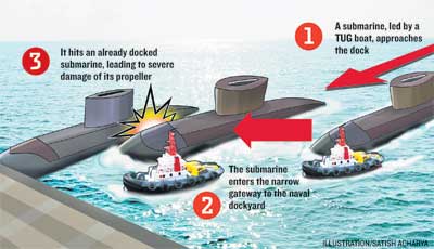
At the time, one submarine was docked, while the other was being towed alongside it. The damage was minimal because of the low speed. The Kilo-class 877EKM attack submarine is capable of touching 11 knots on the surface and 20 knots underwater. It is still not clear whether the accident was due to human error or bad weather. Prima facie, the mishap has been attributed to an error of judgement. High-level inquiry. The navy ordered a high-level inquiry into the mishap, but remained tight-lipped about the incident. Naval spokesperson Capt Manoharan Nambiar said he was on leave and had no information on the incident. His deputy, A Vispute, did not respond to an SMS yesterday. The Kilo-class attack submarines were returning to the harbour after a reconnaissance and patrol mission off the city harbour when the collision occurred. Both 2,300-odd-tonne vessels have low noise levels, which could be one of the reasons why they got too close to each other without anybody noticing. INS Sindhuratna was the second Indian naval submarine to be fitted with four ZM-54E1 missiles with a range of 300 km. It has hull-mounted medium frequency digital sonar. This is first time two Kilo-class attack submarines have collided at the naval dock.
Brazilian Navy plans to build, induct 6 nuke, 20 conventional submarines
RIO DE JANEIRO (BNS): With an objective to strengthen its naval forces, Brazil is considering an ambitious programme to induct as many as 26 submarines to its Navy’s fleet. The new fleet of submarines will include six nuclear-powered and 20 conventional subs. While 15 conventional subs will be newly built, the rest five will the upgraded versions of the existing fleet. The Navy plans to built and induct the submarines over the next three decades, the Latin American news agency MercoPress reported. “The navy’s three decade procurement plan and its programme to develop submarines estimates the cost of building the first nuclear powered submarine in 2 billion Euros which already have been earmarked,” the news agency said. Brazil’s first nuclear-powered submarine, being built with technical assistance from France, comes at a higher price as it also involves technology transfer and other capabilities costs. “However the costs of the following subs to be built in Brazil are estimated by the Brazilian Navy in 550 million US dollars,” the news agency said. The 20 conventional submarines, to be built in two lots, will include 15 new subs. Four of these new vessels will be modernised versions of the French Scorpene submarines. In the second batch, Brazil will upgrade its existing fleet of five submarines. Four of them will be the Tapi class based on German technology and the other one will be the Tikuna class, built by the Brazilian Navy. Brazil, in 2008, had inked a deal worth 6.7 billion Euros with France under which it would get four Scorpene conventional submarines and technical assistance to build its own nuclear-powered submarine. The Scorpene subs, being built by French shipbuilder DCNS, are scheduled to be delivered to the Navy by 2021.Brazil would be deploying its submarine fleet primarily for patrolling its territorial waters where huge oil deposits have been discovered in recent times.
SUBMARINE RESCUE.
France, Norway and the UK have joined forces to establish a new submarine
rescue capability for downed submarines below 600m. Several companies
have been contacted to tender bids for the new rescue package, with an
estimated value of US$211 million. The current British rescue vehicle
LR5 is expected to be phased out in 2006.
ROV and SUBMARINE REPLACEMENT MOTORS.
Silvercrest is now the European agent for SME submersible electric motors.
These motors are an excellent and cost effective replacement motor for
all Rovs and manned submarines. Construction in stainless steel or hard
anodised aluminium. All voltages and frequencies. Sizes range from 1/4HP
to 550HP. Also available are a range of matched motor controller drives
and soft starts (bi-directional and variable speed). Custom designs and
problem solving available on request.
SUBMARINE BATTERIES.
Silvercrest can offer high quality traction batteries (lead/acid, 2.2vdc
cells) for all your submarine and submersible requirements. Wide range
of sizes and Ah capacity available. These batteries are built by a leading
manufacturer to a very high technical standard. Prices are substantially
lower than what you have been quoted in the USA or Europe. Call us with
your technical specifications for a quotation.
Wuhan man building business of submarines.
A man in central China's Hubei Province who has invested more 3 million yuan (US$474,419) in building small submarines on his own has completed his first deal and is now trying to attract more investment to expand his buoyant business. Zhang Wuyi, 37, a laid-off textile machinery factory worker in Wuhan, has received three orders this year, with each submarine selling for about 200,000 yuan, the Wuhan Evening News reported yesterday. Zhang told the paper that he learned from Li Mingyu, who was honoured as "the first manufacturer of a self-made submarine in China" and led Zhang into the business. "At first I was just an onlooker, watching Li building the submarine just like watching a joke," said Zhang. But when he realized there was a great market demand for small submarines, he decided to participate. He started by renting his original factory workshop to use as his own manufacturing base. He has about 10 employees. Zhang's chief engineer, surnamed Li, used to work in the shipbuilding industry. He told the newspaper that he was moved by Zhang's persistence and decided to help. With Li's assistance, Zhang successfully built his first commercial submarine and sold it to Cong Zhiwen, a businessman from Dalian, a north-eastern city. Li said the submarine can dive to about 30 meters and work 10 hours a day. It can hold two people and is equipped with a mechanical arm and underwater camera.
Ukraine's Only Submarine on Sea Trials.
Ukraine’s only submarine, 40-year-old 'Zaporozhye', has left the port of Sevastopol on the Black Sea for sea trials after many years of repairs. The Soviet-era Foxtrot class (Project 641) diesel-electric submarine stood grounded at a dock in Sevastopol for years without repair and became a symbol of the demise of Ukraine’s navy. Russian engineers repaired and serviced the submarine and a crew of Ukrainian submariners was trained at Russian naval bases. “The sea trials of the Zaporozhye submarine is an important event for the Ukrainian navy,” Defense Minister Dmytro Salamatin said. “Successful sea trials will ensure the revival of Ukraine’s submarine fleet.” The trials will test the submarine’s power plant and other key equipment while sailing on surface. Though the submarine was built 40 years ago, the vessel has been upgraded with new equipment and will certainly raise the combat capability of the Ukrainian navy. Submarines of this type are most efficient in the Black Sea as they feature low radar and noise signatures.
Human error causes submarine grounding.
A Board of Inquiry (BOI) has found that human error was a key contributing factor in the grounding of HMCS Corner Brook in Nootka Sound June 4, prompting Commander Royal Canadian Navy to relieve LCdr Paul Sutherland of his command. The submarine struck the south eastern wall of Zuciarte Channel, more than 500 yards from its intended position while the boat was conducting Submarine Officer Continuation Training. A military BOI formed to look into the matter, spoke to 15 witnesses prior to reaching its findings. "The BOI concentrated on the events that happened on board, on that day, so most [who were interviewed] were members of the crew or riders at the time," says Capt (N) Luc Cassivi, Deputy Commander of Canadian Fleet Pacific. The BOI determined the submarine's technical systems did not contribute to the incident. Submarine commanders usually give the boat a buffer zone to allow for any errors in equipment or ocean currents when submerged. The established practice of recognizing what is referred to as a "pool of errors" was not properly followed in this case.” This grounding was avoidable," said Capt (N) Cassivi. "It was caused by a failure to properly account for the positional uncertainty of the submarine in accordance with approved dived submarine navigational practices and techniques when operating in confined waters."
The World’s Biggest Nuclear Submarine Is the Sneakiest.
While the Red October may not have been an actual submarine, the Russian Typhoon class that it’s based on certainly is. Turns out, Hollywood didn’t have to embellish many details for the film—Typhoons really can sneak up on you. The Typhoon is a class of nuclear-powered ballistic missile submarines developed by the USSR and deployed throughout the 1980s. The fleet of six submarines were built at the Severodvinsk Shipyard on the White Sea. The largest submarines ever constructed, they measure 175 meters long with a submerged displacement of 48,000 tonnes. The Typhoon class is capable of staying submerged for up to three months at a time. These massive ships employ a five-layer, pressurised hull—the outermost of which is covered in sound-dampening plates—which allows the ship to dive to a maximum depth of 400 meters. The five-layer style also allows for an overall wider design than a conventional submarine. This helps create the necessary living space for the Typhoon’s crew of 160 sailors, and it provides additional protection against hull breaches. A Typhoon class sub is powered by two OK-650 pressurised-water nuclear reactors, each of which provides an excess of 250,000 HP. This allows the subs to reach a top speed of 22 knots on the surface and 27 knots when submerged. The Typhoon was designed to compete with America’s Ohio class subs, which were capable of carrying up to 192 100-kiloton nuclear warheads. Typhoons carried a primary cache of 20 RSM-52 SLBMs, each of which contained up to 10 MIRV warheads. These missiles were designed so that a Russian sub would be able to launch them safely and discreetly from beneath the ocean’s surface. The missiles were also capable of breaking through Arctic ice floes during launch. The missile systems that the Typhoon class use are reaching the end of their service lives. Three of the ships have been retired, two have been placed on reserve, and the flagship of the Typhoon fleet, the TK-208 Dmitry Donskoy, has been retrofitted and is in field testing with a new weapon system.
Canadian Submarines.
Back in the 60's the Royal Canadian Navy fielded a small number of reasonably capable submarines, the Oberon-class boats we bought from the UK. We had five of these subs. Introduced in 1965 they were decommissioned in the late 90's, a commendable service life. As the Oberon boats were being phased out Canada went shopping for replacements and, voila, the Royal Navy happened to have four "nearly new" Upholder-class subs it was looking to unload. These subs had been mothballed after just four years of somewhat chequered service. During construction of the first boats it was recognized that the weapon-discharge system design did contain flaws. The torpedo tube slide valve controlling operation of the torpedo tube doors could have, under certain system failure conditions, allowed the opening of the inner door while the outer door was open. The flaw was quickly fixed in the first three boats and the modifications included in the fourth boat while still under construction. Miscalculations were made in the design of the main-motor control circuitry. During the sea trials of Upholder, when performing the specified trial for an emergency reversal ("crash back"), a flash-over incident occurred, which resulted in the complete loss of all power and propulsion. On investigation, this was traced to a fault in the design of the control circuitry insulation, resulting in a battery short circuit current of more than 60,000 amperes. The diesels were originally designed for use in railway locomotives, and were not intended to be rapidly stopped and started. Shutting them down after snorkelling led to many failures. Similarly, the motor-generators were operated at full power for longer than expected, and consumed brushes and filters rapidly (the brush problems were not specific to the Upholders, and were a widespread issue on all UK RN vessels at that time). Canada bought these boats in 1998 only to find them chock full of gremlins. Fourteen years later the Canadian navy hopes to have one of them operational this year. It's now thirty years or more since those submarines became operational with the Royal Navy. Thirty years in submarine years is just about a full lifetime. So not only are Canada's subs about to enter service as geriatrics, they're no longer state of the art in the engine room where it really counts. The propulsion units of these diesel/electric subs are a somewhat advanced version of what submarines have used since WWI. That is so yesterday. A big disadvantage to conventional, or non-nuclear, subs has been that they could use their diesel power only while surfaced or while running just below the surface using a snorkel. One way or another they needed a source of air to run at full power. Nuclear boats were air independent and could chug along in the ocean depths for months at a time. Conventional subs bridged the gap recently with the introduction of air-independent propulsion engines. The latest German submarines of the 212 class use fuel cell technology that allows them to cruise fully submerged for weeks. This gives them an endurance capability vastly greater than our vintage subs and somewhat similar to nuclear submarines without the noise penalty of nuclear power units. Why does this matter, especially to Canada? For the first time in our nation's history we're probably going to have a genuine need for a submarine capability, that's why. The Arctic Ocean is going to become ice-free. That means Canada's northern waters are destined to become a major shipping route. It also means the Arctic Ocean will see something akin to a gold rush in the pursuit of seabed resources from oil and gas to mineral wealth. That in turn will fuel tensions over unresolved territorial disputes. That will also lead to new and expanded military presences in the far north. There will be no shortage of legal, diplomatic, commercial and military muscle-flexing in the decades ahead. Right or wrong, like it or not, Canada will need to establish and maintain a credible presence to uphold our sovereignty and protect against encroachment. You snooze, you lose. It's that simple. Submarines, especially of a type our potential rivals cannot readily detect, are essential for defending Canada's north. That means we need modern boats that are capable of silent, extended patrolling underwater. Let's face it, if Harper gets his way and Canada does wind up saddled with a few dozen single-engine, limited range, minimal payload F-35s, we can pretty much kiss goodbye any meaningful ability to defend the vast north from the air. We will need something to pick up the slack. Which brings us back to Canada's not-ready-for-primetime Victoria class subs. It is possible to retrofit those boats with air-independent propulsion systems but is it feasible given their age, remaining usable life, ongoing reliability questions and the substantial cost? Anyone who has owned an old car knows that sometimes you have to cut your losses and get a new car. It's time for the Canadian government to admit that the Victoria boats were yet another disastrous mistake brought to us by the dimwits that populate our National Defence headquarters. It's probably time to stop throwing good money after bad. It's probably time to go shopping for new boats. This time we might even be able to get new for cheap. Greece has several new boats on order from the Germans and it's looking like Greece is a bit short on Euros to pay for them.
Nations face-off beneath the waves.
The Yomiuri Shimbun Chinese submarines deployed at a naval base at Yalong Bay, Hainan Island, China The world has been thrust into a period of great change due to China's emergence and the geopolitical decline of Western powers. This series of articles deals with the formation of a new international order, and potential leadership changes in the United States, China and Russia this year. This first instalment focuses on an underwater tug-of-war between U.S. and Chinese submarines in the Pacific Ocean. An underwater tug-of-war is intensifying among countries such as China, Russia and the United States in the seas around Japan. Vietnamese Defence Minister Phung Quang Thanh, who comes from Vietnam's army, requested an inspection of a Maritime Self-Defence Force submarine when he visited Japan in October. He visited the Makishio, a main submarine of the MSDF Submarine Flotilla 1, in the city of Kure, Hiroshima Prefecture. Made in Japan, the state-of-the-art submarine boasts a displacement capacity of 2,750 tons and is 82 meters in length. It can travel underwater silently and has stealth capabilities. The Vietnamese defence minister paid close attention to the Makishio's interior. It was rare for the MSDF to show the military leader of a non-allied country the craft's interior, which is full of secrets. The commander of the Vietnamese Navy also visited Japan in December. Vietnam's military leaders visited Japan and contacted the MSDF in succession because the country is now rapidly trying to build its own submarine fleet. The first of six Kilo-class Russian-made submarines Vietnam purchased in 2009 will be delivered in two years. Because it can travel silently underwater, a submarine is a strategic weapon. It has the offensive capability to destroy enemy ships and disrupt their transportation routes. It also has spying capabilities and can collect intelligence right under an enemy's nose. The very existence of a submarine can restrict an enemy's moves. Vietnam will employ submarines to deal with territorial disputes with China in the South China Sea. A Vietnamese source said the nation has begun receiving assistance from Russia and India to train its submarine crew members. "We've already made a request to Japan to help us operate submarines and train crew members," he said. When the Vietnamese defence minister visited Japan, Tokyo and Hanoi confirmed a multilateral cooperation security policy out of concern for China's ambitions to increase its influence in the South and East China seas. The two governments also signed a memorandum to promote mutual defence exchanges. Submarines would also help counter Beijing's strategy of denying the U.S. Navy access to and intervention in seas close to China. Beijing possesses more than 70 submarines, including state-of-the-art Jin-class nuclear submarines that can launch ballistic missiles. They have reportedly been deployed to China's Hainan Island, where the nation's largest submarine base is located. Hong Kong media have reported that Beijing has an ambitious project to build 30 new submarines by 2020. This suggests China, the world's second-largest economic power, is seriously considering a "private" plan to divide the Pacific Ocean into two and control one of the halves. The United States would control the other half, with Hawaii at its border. A high-ranking officer of the Chinese Navy revealed the plan's existence to the commander-in-chief of the U.S. Pacific Command in China as a "private proposal" in 2007. This plan, however, is a grave challenge to the United States and runs counter to the very idea of freedom of navigation in international waters being part of its national credo. "China's emergence as a regional power has the potential to affect the U.S. economy and our security in a variety of ways," according to a defence strategy report released by U.S. President Barack Obama's administration on Jan. 5. It declared the U.S. military will abandon its conventional strategy to prepare for large-scale wars in two regions at the same time, and "will of necessity rebalance [efforts] toward the Asia-Pacific region." The U.S. submarine fleet, the strongest in the world, would head toward the west in the Pacific Ocean. Washington is planning to deploy 60 percent of its aircraft carriers and submarines in the Asia-Pacific region. Attack submarines would be deployed forward to hunt enemies and protect U.S. aircraft carriers from surprise attacks by Chinese submarines. According to a report issued by the U.S. Congressional Research Service, the U.S. Navy has deployed three attack nuclear-powered submarines in waters near Guam. The report also says three others of the same type and two cruise-missile submarines have been deployed in waters off the U.S. mainland's west coast. A U.S. nuclear submarine is also planned to visit the western part of Australia. A 21st-century version of the "Great Game" has begun between the United States and China under the western Pacific. With Vietnam joining the link between the United States and its allies, a loose but broad coalition is forming against China. In the northern part of the Pacific, Russian nuclear submarines, meanwhile, are observing the United States and China's moves
Subs Going Down in Strength, Numbers.
The U.S. Navy submarine force will lose significant numbers as well as capabilities over the next 18 years, according to a group commander. Rear Adm. Richard Breckenridge, USN, the commander of Submarine Group Two, outlined the reductions for a panel audience at West 2012 in San Diego. These reductions are part of an overall effort to reduce the size of the force. The number of attack submarines will decline from 55 to 40 by 2030. All eight SSG cruise missile submarine crews will be removed from the force. Adm. Breckenridge pointed out that the submarine force has declined from 21,000 to 16,000 sailors over the past 12 years. Yet, the service maintained the same number of crews. With the new submarine reductions, the Navy will go from 91 submarine crews to 60 crews amid a more challenging global security environment. Undersea forces are undergoing a transformation that began with the Virginia-class boats, the admiral observed. Not since the days of the USS Nautilus, he said, has the Navy made such significant changes in undersea platform design. These new approaches will help the Navy accommodate changes in the force and its mission.
The War Spreads To The Caribbean.
April 25, 2012: On March 30th, the U.S. Coast Guard captured its 30th cocaine smuggling submarine, in the Caribbean. This is the fifth such capture in the Caribbean, with the other 25 captured in the Pacific. It's currently estimated that 80 percent of the cocaine smuggled into the United States leaves South America via these submarines or semi-submersible boats. Most of these craft are "semi-submersibles". They are 10-20 meter (31-62 foot) fiberglass boats, powered by a diesel engine, with a very low freeboard, and a small "conning tower", providing the crew (of 4-5), and engine, with fresh air, and permitting the crew to navigate. A boat of this type was, since they first appeared in the early 1990s, thought to be the only practical kind of submarine for drug smuggling. But in the last decade the drug gangs have developed real submarines, capable of carrying five tons of cocaine that cost a lot more, and don't require a highly trained crew. These subs borrow a lot of technology and ideas from the growing number of recreational submarines being built. The Colombian security forces and other Latin American navies have been responsible for most of these vessel captures. Most of these boats are sunk by their crews when spotted, but the few that were captured intact revealed features like an extensive collection of communications gear, indicating an effort to avoid capture by monitoring many police and military frequencies. The Colombians have captured several of these vessels before they could be launched. In the last few years, the Colombians have been collecting a lot of information on those who actually build these subs for the drug gangs and FARC (leftist rebels that provide security, and often transportation for moving cocaine.) That includes finding out where the construction takes place. Last year Colombian police arrested eighteen members of a gang that specialized in building submarines and semi submersible boats. As police suspected, some (five) of those arrested were retired or on active duty with the Colombian Navy (which operates two 1970s era German built Type 209 submarines). These arrests were part of an intense effort to find the people responsible for building subs for cocaine gangs. Find the builders, and you stop the building efforts. Since cocaine cartels in South America began using submarines and semi-submersible craft to transport cocaine north, the U.S. and Colombia have been desperately seeking the specialists responsible for designing and building these craft. Last year Argentina revealed they had arrested one of the main organizers of the sub building operation. The suspect, Ignacio Alvarez Meyendorff, was identified as working for the Colombian Norte del Valle drug cartel, and in charge of logistics for the submarine construction project. It's believed that Meyendorff was tracked down via information obtained by the U.S. Office of Naval Intelligence (ONI). Apparently, Meyendorff, or documents captured when he was arrested, provided enough data to make further arrests, and run down the location of many of the subs. The submarines that have been captured have, on closer examination turned out to be more sophisticated than first thought. The outer hulls are made of strong, lightweight, Kevlar/carbon fiber that is sturdy enough to keep the sub intact, but very difficult to detect with most sensors. The hulls cannot survive deep dives but these boats don't have to go deep to get the job done. The diesel-electric power supply, diving and surfacing system and navigational systems of captured subs was often in working order. It was believed that some of those who built these boats probably had experience building recreational subs. The sub builders also had impressive knowledge of the latest materials used to build exotic boats. It had already become clear that something extraordinary was happening in these improvised jungle shipyards. It was only two years ago that Ecuadoran police found the first real diesel-electric cocaine carrying submarine. It was nearly completed, and ready to go into a nearby river, near the Colombian border, and move out into the Pacific Ocean. The 23.5 meter (73 foot) long, three meter (nine feet) in diameter boat was capable of submerging. The locally built boat had a periscope, conning tower and was air-conditioned. It had commercial fish sonar mounted up front, so that it could navigate safely while underwater. There was a toilet on board, but no galley (kitchen) or bunks. Submarine experts believed that a five man crew could work shifts to take care of navigation and steering the boat. The boat could submerge to about 16 meters (50 feet). At that depth, the batteries and oxygen on board allowed the sub to travel up 38 kilometers in one hour, or at a speed of 9 kilometers an hour for 5-6 hours. This would be sufficient to escape any coastal patrol boats that spotted the sub while it moved along on the surface (its normal travel mode.) The boat could also submerge to avoid very bad weather. The sub carried sufficient diesel fuel to make a trip from Ecuador to Mexico. There was a cargo space that could hold up to seven tons of cocaine. The sub was captured where it was being assembled, and a nearby camp for the builders, appeared to house about fifty people. A lot of evidence was collected, and apparently the U.S. DEA (Drug Enforcement Agency) used that to develop clues about who was involved. It was the DEA that put together the pieces that led to identifying Meyendorff and locating him in Argentina. The Ecuadoran boat was the first such sub to be completed, but not the first to be attempted. A decade ago, Russian naval architects and engineers were discovered among those designing and building a similar, but larger, boat. However, that effort did not last, as the Russian designs were too complex and expensive. It was found easier to build semi-submersible craft. But more and more of these new type subs are being found.
Submarines from North Korea may be on the move.
Submarines of the North Korean West Sea Fleet Command have recently begun underwater operations, intelligence sources in the South told the JoongAng Ilbo yesterday. “The submarines were docked during the winter, but they recently began moving as the weather warmed up,” a source said. “Of them, we could not confirm whereabouts of one or two submarines, so we believe they are engaged in underwater operations.” North Korea operates about 70 submarines, and they are normally docked at the bases near Nampo or Bipa Cape during the winter for maintenance work or the crew’s ground training.
Russia Offers India Air-independent Propulsion Systems.
Russia has offered to help India build air-independent (closed cycle) propulsion systems for installation in Amur 1650 class submarines and also to equip future possible joint Indian-Russian built vessels, according to Viktor Komardin, the deputy head of Rosoboron export's delegation at the recent Defexpo Indian defense show. The Amur 1650 is one of several contenders, including the Scorpene (France), Type 214 (Germany) and S-80 (Spain) in a tender for the Indian Navy for six submarines with a total value of $11.8 billion. "Russia is currently completing tests of a new air-independent propulsion system, which could be installed not only on the Amur 1650 but on jointly developed boats," Komardin said. "This is a critical factor for the Indians. So our chances here are good," he added. Rosoboronexport, Russia's defense sales holding, has already offered India its Amur 1650 boat, which started trials with the Russian navy in 2010. The Amur has an armament of multirole torpedos and Klub anti-ship missiles, and can also strike land-targets with advanced cruise missiles, which may include the India-Russian Brahmos. The Amur 1650 has a good chance of winning the tender, Komardin claimed, thanks to its ability to remain submerged for over 25 days using its air-independent propulsion, and also its long-range weaponry. Similar foreign boats can only stay submerged for 15-20 days. Air-independent submarines, usually using hydrogen-orygen fuel cells, are quieter than conventional diesel-electric boats, and do not have to surface or use snorkel tubes to breathe air, which makes them vulnerable to detection by radar and other sensors.
Submarines and undersea rigs may tap into Arctic oil riches.
OIL companies are planning to create huge underwater rigs on the seabed of the Arctic Ocean, possibly serviced by a fleet of manned submarines. The creation of giant underwater oil and gas plants with all the machinery used to extract fossil fuels beneath the waves would protect them from the extreme weather, including ice and storms that affect the Arctic. While oil companies already site some of their machinery underwater, the aim is to move all of it to the seabed, including processing plants that strip contaminants from oil and gas before compressing it to send ashore. However, one drawback is that servicing would still have to be carried out by surface vessels, at risk from storms and ice. At least one firm is considering using submarines instead. The vessels, 40m long and able to descend to depths of 460m, would be able to remain submerged for weeks, servicing the underwater factories. Carrying between 10 and 14 people, they would have two hulls either side of a cargo bay able to carry 50 tonnes of machinery. "The Arctic has enormous fossil fuel reserves but there are huge problems in getting the oil and gas out safely," said Tor Berg, who is designing the vessel. "A submarine can work under the ice and storms for weeks at a time, making sure that these installations are installed properly and work safely." Mr Berg, a principal research engineer at the Norwegian Marine Technology Research Institute in Trondheim, unveiled the submarine design at last week's Arctic Frontiers conference in Tromso, Norway, where executives from energy firms met to discuss the challenges of extracting fossil fuels in the far north. Statoil, the Norwegian state oil firm, has expressed an interest in the submarine, which could help to meet the challenges of exploiting the Barents Sea, north of Norway, home to some of the world's greatest untapped gas and oil reserves. Those riches are matched only by the extremity of the conditions, including seas that freeze in winter, icebergs capable of wrecking a rig or ship, prolonged darkness and Arctic storms. Statoil already operates almost 500 subsea wells that are fixed to the seabed rather than placed on surface oil rigs. Such equipment is connected to land by electrical cables that supply power and by pipes that take oil and gas to shore. There are problems when such machinery needs to be installed, replaced or serviced. At present, ships usually send a remote-controlled unmanned submarine but such systems are often unable to operate in heavy weather. According to the US Geological Survey, the Arctic contains oil equivalent to at least 13 per cent of the world's known reserves. Gas reserves are equivalent to about 30 per cent of known reserves.
Tourists on the Great Barrier Reef (new mini-submarines).
Great Barrier Reef Submarines has begun offering the experience at Fitzroy Island, a 45-minute ferry ride from Cairns in Queensland. Two passengers and a pilot can fit in the 4m wide, 1.8m high mini-submarine, which was designed in Canada. Passengers enter the cockpit through an opening in the back of the hull guided by a safety diver and met are inside by the pilot. Once inside they sit on window seats either side of the cockpit cabin. "The cabin is cosy but it's surprisingly roomy for three people,'' Great Barrier Reef Submarines owner Richard Chapman said. "You duck dive into it and sit up to your waist in water but your upper body is in fresh air. "You're in a bubble of air.'' While the mini-submarine is capable of going as deep as 40m, you only have to go 6m to get to the bottom of the reef in the area it is used. Passengers have to equalise when the submarine dives or ascends, similar to scuba diving. Tours will be conducted during the day and at night and cost $150 for 30 minutes. A pocket of air is trapped inside the cockpit of the sub, like an upside-down cup traps air when pushed underwater. The air is replenished from the scuba tank supply. The Resort Submarine travels at a maximum speed of 7.5km per hour. It works on an ambient pressure design, so the air pressure inside the sub is the same as the water pressure outside. No certified pressure hull is required because there is no danger of the hull collapsing as no differential pressure is being exerted on the hull by the water. This allows for the use of a light and durable fibreglass hull. The submarine is driven by electric thruster propellers which move the sub forward, backwards and up and down, which makes it easier to manoeuvre than traditional ballast tank and propeller submarines.
Sagem modernizing South Korean subs.
South Korea has chosen Sagem of France to modernize the navigation system on its navy's KSS-1 class Chang Bogo submarines. Each KSS-1 will be fitted with two Sigma 40XP inertial navigation systems, integrated in the ship's combat system. The KSS-1 is a conventional type U-209 submarine displacing 1,200 metric tons and is built by Daewoo Shipbuilding and Marine Engineering. Sagem's Sigma 40XP is a state-of-the-art inertial navigation system, combining high-performance laser gyros and advanced digital filtering techniques. The core laser gyro technology has amply proven that it is the most appropriate technology for the harshest operational environments, such as those experienced by submarines during dives. By modernizing the KSS-1 class submarines' navigation systems, they will significantly enhance operational capabilities to meet the evolving needs of the South Korean navy, Sagem said. It said the contract consolidates Sagem's leadership in the high-performance navigation market for submarines. Sagem navigation systems now equip 11 different classes of submarines -- nuclear, air independent propulsion, and conventional -- totaling more than 50 ships, as well as some 300 surface vessels.
Crew remained inside Russian nuclear submarine as firemen battled to put out massive blaze.
A massive fire aboard a Russian nuclear submarine at an Arctic shipyard has finally been extinguished. Several crew members remained inside the Yekaterinburg sub as the blaze raged overnight at a repair dock in Roslyakovo shipyard in the Murmansk region. Defence Ministry spokesman Colonel Igor Konashenkov insisted there was never any danger of the fire spreading inside the sub and said the crew reported that conditions on board remained normal. It remains unclear whether they were trapped by the flames or ordered to remain behind.
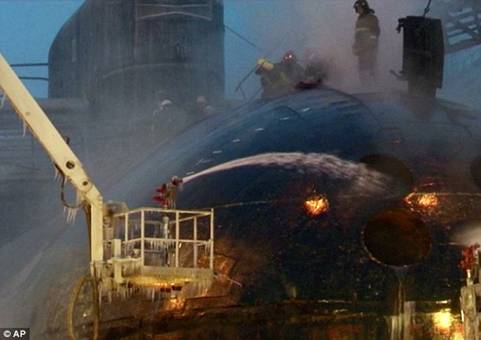
Massive blaze: A fire aboard a Russian nuclear submarine at an Arctic shipyard has been extinguished. Several crew members remained inside the sub during the incident. It remains unclear whether the crew members were trapped by the flames or ordered to remain behind in the sub. Seven others who inhaled poisonous carbon monoxide fumes were evacuated to hospital. Pavel Falgenhauer, a top Russian political analyst, warned: 'This is a very serious blow to Russia's nuclear deterrence capabilities. 'The loss of a strategic nuclear submarine, especially one that had been due to remain in service for at least another decade, hurts a lot.' President Dmitry Medvedev has given assurances that there was no radiation leak and that the vessel's nuclear-tipped missiles were not on board. He has summoned top Cabinet officials to report on the situation and demanded punishment for anyone found responsible. Military prosecutors have launched an investigation into whether safety regulations were breached. The fire, which broke out yesterday and shot orange flames high into the air throughout the night, was put out this afternoon. Firefighters continued to spray the vessel with water to cool it down, Emergency Situations Minister Sergei Shoigu said. Russian state television earlier showed the rubber-coated hull of the submarine still smouldering, with firemen gathering around it and some standing on top to douse it with water. Seven crew members who inhaled carbon monoxide fumes were evacuated to hospital. Most modern submarines' outer hulls are covered with rubber to make them less noisy and more difficult for an enemy to detect. Norway's Radiation Protection Authority across the border reported it has not measured any increased radioactivity. The governor in Finnmark, Norway's north-eastern province that borders Russia, and the radiation agency complained about the Russian response. Gunnar Kjoennoey said: 'There have been problems to get clear information from the Russian side. We have an agreement to exchange information in such cases, but there has been no information from the Russian side so far.' Russia's military said the blaze started on wooden scaffolding and then engulfed the sub's outer hull. The vessel's nuclear reactor had been shut down and its nuclear-tipped missiles and other weapons had been unloaded before dry-dock repairs, it said. Toxic fumes from the blaze had spread to the town of Roslyakovo where the shipyard is located, but officials said there was no need to evacuate local residents.
RUSSIAN SUBMARINE DISASTERS.
The huge fire which engulfed the Yekaterinburg nuclear submarine is the latest catastrophe to afflict Russian submarines in recent years. In November 2008 20 Russians choked to death on poisonous gas on board the Nerpa nuclear submarine. The men suffocated when faulty firefighting equipment went off by mistake while the new craft was carrying out underwater tests in the Sea of Japan. In August 2003, two member of a 10-man crew on a Russian K-159 sub died when the vessel sank in the Barents Sea. The submarine's nuclear reactor was shut down at the time the vessel sank about three nautical miles north west of Kildin Island. But by far the worst Russian sub disaster in recent memory happened on the Kursk (pictured above) in August 2000. An explosion during exercises sent the nuclear sub to the bottom of the Barents Sea, killing all 118 men on board. Russia refused offers of help from Britain and the United States and a Russian rescue attempt failed. The former director of the biggest shipyard in the area said the fire was probably caused by the failure to take proper safety precautions, such as coating the scaffolding with special sprays to make it fire-resistant. Nikolai Kalistratov said: 'It was either lack of professionalism or an attempt to save money that has turned into huge losses.' The Yekaterinburg is a Delta IV-class nuclear-powered submarine that normally carries 16 nuclear-tipped intercontinental ballistic missiles. The 548ft-long vessel has a displacement of 18,200 tons when submerged. The chief of the General Staff of the Russian armed forces, General Nikolai Makarov, led a team of senior military officials to Roslyakovo to oversee the emergency response. The damage from the fire could be so massive that the submarine would need to be scrapped. But Deputy Prime Minister Dmitry Rogozin, who is in charge of the nation's military industries, today said that the submarine will rejoin the navy after repairs. The Russian navy suffered its worst accident in August 2000, when the Kursk nuclear submarine exploded and sank during naval maneuvers, killing all 118 crew members aboard. A 2008 accident at the Nerpa nuclear-powered submarine killed 20 Russian seamen and injured 21 others when its fire-extinguishing system activated in error and spewed suffocating Freon gas.
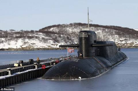
Before the blaze: Russia's nuclear-powered submarine Yekaterinburg pictured earlier this year.
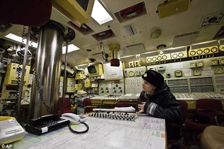
At the helm: A Russian sailor sits in the control room of the Yekaterinburg submarine at an earlier date.
Russian Eyes Mariana Trench as Cameron Prepares to Dive.
Russia is joining the race to reach the bottom of the Mariana Trench, the deepest ocean crevice on Earth, famous explorer Artur Chilingarov has said. Chilingarov, the deputy head of Russia's Geographic Society, is mostly associated with the Kremlin's Arctic ambitions. He told a Moscow news conference on Monday that three design bureaus were working on submarines able to dive to the lowest points of the trench, which plunges nearly 11 kilometers down. His comments come a month after Russia claimed to have penetrated a vast Antarctic sub-glacial lake that is believed to have remained untouched by man for at least 14 million years. But Yury Konovalov, a chief engineer at St. Petersburg's Malakhit design bureau, said the submarine project was still in the draft stage. "It is no secret that funding is needed to pursue such projects," Konovalov told RIA Novosti. "We're no worse than foreigners, but funding is essential." The two other bureaus declined to comment. At its deepest, the Mariana Trench in the western Pacific extends down to 10,994 meters, Jim Gardner, a U.S. marine geologist who has spent the last five years mapping its seafloor, said in e-mailed comments. At that depth, the pressure is 1,000 times that at sea level. The world's first - and still only - manned voyage to the bottom of the Mariana Trench was made by Swiss engineer Jacques Piccard and U.S. Navy Captain Don Walsh in January 1960. They spent just 20 minutes at the ocean floor. The landing stirred up so much bottom sediment that peering out of the porthole was like "looking in a bowl of milk," Walsh said in a BBC documentary last month. And today, Hollywood filmmaker James Cameron is about to become the third human ever to challenge the record-breaking depth. Cameron's is one of four U.S. teams currently racing to make it down to the world's deepest spot, and he looks very likely to clinch it. The Abyss and Titanic director, known for his passion for ocean exploration, set sail for the trench on Tuesday morning and is now waiting for calm seas to begin his nine-hour dive, the BBC reported. Cameron has said he plans to spend six hours in the bright green one-man submarine, called the Deepsea Challenger, filming his voyage from the surface all the way to the bottom. "Every single dive, I'm going to see something no one's ever seen before," Cameron told the BBC. "I'm going to do my best to image it, light it properly, bring it back in 3D - grab samples if I can, grab rocks if I can." "We are there to do science, but we are also there to take the average person who only imagines these things and show them what it is really like," he said.
Russian Navy to get 10 diesel submarines by 2020.
The Russian Navy is planning to receive up to 10 diesel-electric submarines by 2020, a Navy spokesperson said. "The Russian Navy expects to receive 8-10 diesel submarines by 2020," the official said on Monday. The new submarines will strengthen primarily Russia's Baltic and Back Sea fleets, he added. Russia's Admiralteiskie Verfi shipyard on Monday launched the construction of a Project 636.3 modernized Kilo-class submarine. The Project 636 vessels, crewed by 52 submariners, have an underwater speed of 20 knots, a cruising range of 400 miles with the ability to patrol for 45 days. They are armed with 18 torpedoes and eight surface-to-air missiles. The spokesperson said the improved Kilo class submarines will feature advanced "stealth" technology, extended combat range and ability to strike land, surface and underwater targets. The Russian Navy currently has about 20 diesel-electric submarines deployed to protect Russia's territorial waters.
Russian submarine future.
Russian submarine fleet is going through a major revamp, with new subs joining ranks with the obsolete Russian U-boats. The future of the country’s fleet will be decided in the upcoming years, which will see the implementation of the state arms program. The K-535 Yuri Dolgoruky, a Borey class flagman submarine equipped with ballistic missiles, will enter the Russian service by summer 2012 with another two nuclear subs, the K-550 Alexander Nevsky and Vladimir Monomakh, to follow suit in autumn. A ceremonial keel laying of the fourth nautilus, which has been around two years in the making, will also be held this year. The number of submarines is surging alongside their construction tempo. The Yuri Dolgoruky was built in 17 years, while the Alexander Nevsky and Vladimir Monomakh have cut that time to eight years each. The construction timeline of the other two subs is expected to dip by another several years, reaching six years or even less. The naval component of the Russian missile defense shield is therefore short of nothing but multipurpose submarines that are capable of operating under various circumstances, including escorting submarine missile carriers and eliminating enemy submarine cruisers. That is the Russian construction program for multipurpose nuclear and diesel submarines. According to the plan, the Russian subs fleet is set to receive from eight to ten diesel U-boats and ten Yasen class multipurpose subs. The first submarine of this class is completing its test period; the second is soon to come off the stocks, while the other eight subs are only slated to be built under the state arms program. The Russian submarine fleet consists of 27 multipurpose nautili, only 10 to 12 of which will remain in service after 2020, mainly the Oscar II and Akula class ones. The same number of diesel submarines will be able to get past the 2020 deadline unscathed. By that time, the rest of the current U-boat fleet will deteriorate and be scrapped. Thus, the Russian fleet will have to part with around 26 to 30 out of its 50 submarines and get no more than 20 subs in return – if everything goes according to the state arms plan. The fact that this number is not enough nowadays, considering that many of the subs are either being repaired or waiting to be repaired, the six to ten submarine deficit can turn out to be crucial. One of the regions Russia needs to maintain its presence in is its Far East, where Japan keeps 18 modern diesel-powered subs at all times and constantly revamps its fleet. Tokyo also has advanced surface and anti-subs forces at its disposal. Russia’s Pacific Fleet is less numerous, a reality which can threaten the balance of power in the region where submarine parity is the only way of staying afloat. Although the Russian fleet formally disposes of the same amount of multipurpose and diesel U-boats, the majority of them are unfit for combat. Moreover, there are no cutting-edge submarines whatsoever in the Russian Far East fleet, with most of the Pacific brigade being over 15 years old, whereas out of 18 Japanese submarines 15 subs have entered service over the past 15 years. In order to cover the existing deficit of multipurpose subs, Russia needs to implement a full-scale modernization and overhaul plan and bolster the construction of modern submarines, both diesel and multipurpose ones. However, that ambitious plan could see the overall price of the Russian fleet revamp sky-rocket. The Yasen class submarines are quite expensive, while Russia needs to find a cheap and effective solution to fix its deficit problem, a solution like the Soviet time Victor class submarine or the modern US Virginia sub. Still, nothing is known about the Russian military’s plans to build such a submarine or about the year it will be able to enter the Russian service .
RI submarines on par with neighbors after overhaul.
The capabilities of Indonesian submarines are now on par with those fielded by neighboring countries after undergoing an overhaul in South Korea, Navy chief of staff Adm. Soeparno said Monday. He was speaking at a ceremony welcoming the return of KRI Nanggala 402, which had been undergoing an overhaul process for the past 24 months by Daewoo Shipbuilding & Marine Engineering (DSME) in Busan, South Korea. Made in 1981 by German shipbuilder Howaldtswerke-Deutsche Werft in Kiel, the Type 209/1300 KRI Nanggala was the second submarine after being overhauled at DSME facilities after KRI Cakra 401 was overhauled in 2006. “With the completion of the overhaul, now the capabilities of our submarines are on par with submarines deployed by our neighbours,” Soeparno told reporters after the ceremony at the Navy Eastern Fleet Command pier in Surabaya. Malaysia has two French-made Scorpene class submarines. Singapore operates four Challenger-class submarines and two Archer-class submarines that were acquired from the Swedish Navy. Australia operates six Collins-class submarines that were built under cooperation with Sweden. Australia will modernize its submarine fleet by building 12 new larger submarines still in cooperation with Sweden. Vietnam will begin to receive four Russian-made Kilo class submarines from 2015. During the overhaul process, KRI Nanggala was undergoing a retrofit, including replacing the upper structure from bow to stern, some parts of the propulsion system, sonar, radar, weapons system and combat management system (CMS). KRI Nanggala can now submerge to a depth of 257-meters with a top speed of 25 knots, increasing from 21.5 knots. Commanded by Lt. Col. Purwanto, the submarine has a complement of 50 personnel, including a special force unit for infiltration. The implementation of the latest CMS allows the submarine to simultaneously fire four wire-guided surface underwater torpedoes (SUTs) in a salvo at four different targets. The 1,395-ton submarine can also fire eight torpedoes at the same time if needed. The CMS upgrade also allows the submarine to launch sub-missiles at surface or air targets. “There are several types of missiles that can be launched, including Harpoon, Exocet, SUT or other types,” said Col. Tunggul Suropati, former taskforce chief from the Cakra-Nanggala overhaul in South Korea. The Defence Ministry and DSME had signed a contract to procure three submarines worth about US$1.1 billion. The first two submarines will be manufactured in Busan, while the third at state shipyard PT PAL facilities in Surabaya through a transfer-of-technology mechanism. Indonesian engineers will also be involved in the production of the first two submarines.
Navy submarine ran aground after series of errors.
One of the Royal Navy's flagship submarines ran aground off the Isle of Skye because the officer on the bridge was not using the right radar, did not have a chart and was unused to navigating in the dark, an official inquiry has concluded. The 24-page report makes clear that a series of errors led to the £1bn HMS Astute becoming beached early on 10 October 2010, an embarrassment that was compounded when a rescue vessel crashed into its side and caused more damage. Nobody has been court martialed over the incident, but the navy said three officers had faced disciplinary or "administrative" action. The Ministry of Defence would not name those who had faced proceedings. The commanding officer at the time, Andy Coles, lost his post a month after the incident. One of the military's newest and most modern vessels, Astute was undergoing sea trials when it became lodged on a shingle bank between the mainland and Skye. The official service inquiry into the accident notes that the commanding officer was taking a shower as the nuclear-powered submarine was heading for trouble, and that the "root causes of the grounding were non-adherence to correct procedures combined with significant lack of appreciation by the officer of the watch (OOW) of the proximity of danger." The submarine was late for a rendezvous with another ship and ended up "cutting a corner" to get to the right position at the right time, the report states. The OOW told the inquiry team that "he had never been south of the Crowlin Islands on the bridge in the dark before", and that he had been given no specific instructions about what to do, other than the time the rendezvous was due to take place. The submarine's primary radar was not being used because it was "emitting noise", though it was still fully operational. A proper bridge chart was not available until it was too late, the report says. "Although the chart did finally make it to the bridge this was deemed too late and from his evidence it is concluded the OOW did not have any meaningful time to refer to it as events unfolded around him," the report adds. To begin with, the officer of the watch did not have a pair of binoculars, and he then failed to alter course when he was first advised to do so, which meant the submarine was "propelling ahead and heading directly" into danger. "Any situation awareness [he had] when he arrived on the bridge was now rapidly deserting him due to the lack of either radar, a chart or previous experience in this area," the report says. Once Astute had got stuck, senior officers failed to take appropriate action, probably because "the gentle nature of the grounding did not give any cause for immediate concern, and as such no one in any position of responsibility felt there was any immediate threat to the submarine". The report says this was "a regrettable oversight". Early attempts to shift the 7,800-tonne submarine from the bank failed, and minor damage was caused when a towing vessel, the Anglian Prince, hit the Astute during the rescue effort. The inquiry made ten recommendations, including issuing a reminder to the commanding officer "of his responsibilities for safety of the submarine and personnel, in particular the need to provide clear and comprehensive direction and guidance". Rear Admiral Ian Corder, head of the submarine service, said he accepted all the findings, and said: "Remedial actions have either been completed or are under way." Corder said he would not say who had been reprimanded because "this is a private matter between those concerned and the naval service". He added: "The submarine service has learned from this incident. I am confident the incident is not indicative of wider failings."
James Cameron back from dive to world's deepest point.
Filmmaker James Cameron has made it back from his first excursion into the deepest point on the Earth's surface, the bottom of the Challenger Deep at nearly 36,000 feet below the ocean waves.Cameron is the third person to make it to the bottom of the Challenger Deep, and the only person to make the trip alone. His submarine, DeepSea Challenger, took just over two and a half hours to sink over 35,000 feet and the director spent two hours cruising around the sea floor, shooting footage with 3D and regular cameras illuminated by an eight foot bank of lights. ![]()
![]() "I landed on a very soft, almost gelatinous flat plain. Once I got my bearings, I drove across it for quite a distance and finally worked my way up the slope," Cameron said, according to National Geographic, which cosponsored the trip. "The bottom was completely featureless. I had this idea that life would adapt to the deep but I don't think we're seeing that." Cameron had been due to take core samples from the seabed and see if any biological samples could be collected, but after a malfunction in the submarine's hydraulic systems and the loss of some thrusters, it was decided to cut the mission short. Dealing with the extreme depths of the Challenger Deep trench has caused problems in the past. The Trieste, piloted by Swiss oceanographer Jacques Piccard and US Navy Lieutenant Don Walsh, made the trip to the bottom in 1960, but had to abort their visit early after one of the windows cracked after the descent. After he had dropped his ballast, Cameron took just 70 minutes to get to the surface. His arrival was spotted by Microsoft cofounder Paul Allen, another contributor to the mission, who was on hand in his 416-foot mega-yacht Octopus (which has two submarines of its own.) Allen and his boat were there as support craft for the dive. Cameron now plans a second dive using the Deepsea Challenger, this time stringing fiber optic cable with him so that scientists can get real-time data from the site, and has suggested a return in a larger, second-generation vessel.
"I landed on a very soft, almost gelatinous flat plain. Once I got my bearings, I drove across it for quite a distance and finally worked my way up the slope," Cameron said, according to National Geographic, which cosponsored the trip. "The bottom was completely featureless. I had this idea that life would adapt to the deep but I don't think we're seeing that." Cameron had been due to take core samples from the seabed and see if any biological samples could be collected, but after a malfunction in the submarine's hydraulic systems and the loss of some thrusters, it was decided to cut the mission short. Dealing with the extreme depths of the Challenger Deep trench has caused problems in the past. The Trieste, piloted by Swiss oceanographer Jacques Piccard and US Navy Lieutenant Don Walsh, made the trip to the bottom in 1960, but had to abort their visit early after one of the windows cracked after the descent. After he had dropped his ballast, Cameron took just 70 minutes to get to the surface. His arrival was spotted by Microsoft cofounder Paul Allen, another contributor to the mission, who was on hand in his 416-foot mega-yacht Octopus (which has two submarines of its own.) Allen and his boat were there as support craft for the dive. Cameron now plans a second dive using the Deepsea Challenger, this time stringing fiber optic cable with him so that scientists can get real-time data from the site, and has suggested a return in a larger, second-generation vessel.
Iran’s Submarine Force.
In the middle of all the discussion of the possibility of attacks on Iran and a war in the Persian Gulf region, one factor in particular has been largely overlooked. The Iranians have evidently fallen in love with submarines. Brief news stories about the launch of new submarines have appeared repeatedly in the past few years, and yet this phenomenon receives only a passing mention in most articles and reports. No other country in the area (unless one counts Pakistan) operates any submarines. By contrast, the Iranians now could potentially have more than 20. Obviously the Iranian naval establishment thinks it’s on to something, and that their near-term future lies beneath the waves. What do they have in mind? Accurate information about Iran’s submarine force is difficult to acquire. The announcements of new submarines often emanate from semi-governmental Iranian sources, which are known to boast about the capabilities of their indigenous weapons systems. For their part, international journalists often vary widely in their estimates of the size of Iran’s submarine force, with no consistent pattern emerging. In the 1990s and shortly thereafter, the Iranians purchased three Kilo class submarines from Russia. These submarines are diesel-electric attack subs, well known for being quiet. The Iranians subsequently began constructing their own midget submarines, with one craft of the Nahang class and many more of the Ghadirclass. The Iranians may also have acquired a few midget submarines from North Korea, though details are hazy, and these craft may no longer be operational. All of these midget subs can carry two torpedoes or anti-ship missiles, lay mines, and transport commando teams. More recently, the Iranians seem to be seeking to bridge the gap between the midget subs and the Kilos by constructing what they call “semi-heavy” submarines of the Qaaem and/or Fateh class, with more possibly to come. Such submarines, if successful, could complement the Kilos at first and eventually supplant them when the larger submarines reach the end of their service lives. The upshot of all of this is that, even by the most conservative estimates, the Iranians have a sizable submarine force, are seeking to make it larger, and have a substantial head start over any of the other states bordering the Persian Gulf. The reason for this submarine construction binge is very similar to the reason for Iran’s missile program: it circumvents their aerial deficiencies and, in so doing, creates a deterrent to attack. The Persian Gulf is mostly shallow and is littered with shipwrecks from centuries of traffic. Antisubmarine warfare is complicated in such an environment, and smaller submarines have particular advantages. All of the Arab states bordering the Persian Gulf have small navies, and suffering losses to Iranian submarines would leave these kings, sheiks, and emirs able to protect neither their exports of oil nor their imports of vast quantities of consumer goods. The Saudis have the most powerful navy in the region by far, but they are cursed by geography. Some of their most powerful ships are based at a port on the Red Sea, and transferring these elements to the Persian Gulf would necessitate sailing through the Straits of Hormuz. This would likely be a suicide mission in the face of Iran’s mines, submarines, shore-launched missiles, warships, air strikes, and so on. The Arab air forces would surely attempt to eliminate Iran’s naval bases. But the Iranians have likely constructed missiles with that in mind. The multi-billion dollar air forces and navies of the Gulf States are concentrated at very few bases such that even an inaccurate missile is likely to land on something valuable. In the case of a conflict with the United States, the Iranians could not win per se, but this is where deterrence comes into play. Before being overwhelmed and destroyed, Iranian submarines could conceivably sink one or more American ships and/or submarines, resulting in unacceptable casualties for the United States. This strategy is behind most of Iran’s recent military moves, and is common around the world. For this reason, among others, many current and retired American senior military officers oppose any attack on Iran. The military situation for the Israelis is similar. They would love to add the firepower of their own submarines’ cruise missiles to any strike on Iran, but risking the subs would be very foolish at a time of terrible relations with Turkey, upheaval in Syria, and an uncertain future with Egypt. The Iranians would not have acquired so many submarines if they did not think they would come in handy. Thanks in part to these undersea craft, the regime in Tehran may have developed the ability to dominate its neighbours and ward off attack from faraway powers even as most of the foreign policy community has been chasing the spectre of nuclear weapons.
How much for the Scorpenes.
The actual cost of the two French submarines sold to Malaysia could be half of the total amount paid. According to different sources in France, the two Scorpene submarines sold to Malaysia would have cost about 670 million euros (RM2.1billion in 2002*), about half of the total deal.
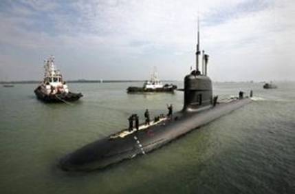
The sale of the two Scorpene submarines to Malaysia, signed in June 2002 by the DCN-I in France and managed by the commercial company Armaris one month later, is part of a larger programme called Soumalais. This programme is divided into four contracts – Scorpene, Malsout, Training and Ouessant. According to the report of the French Ministry of Defence in 2002-2003, total orders for the Malaysian Navy in 2002-2003 were estimated at 686.5 million euros, of which 671. 2 million was for submarines. Knowing the average price of a Scorpene submarine, the question is if it was the price for one or two submarines. SIPRI, the global database used by researchers in defence, mentioned that France and Spain exported one submarine each to Malaysia, as part of a 1.2 billion euros deal. It also showed that in 2009 (date of the delivery of submarines), US$335 million was paid by Malaysia to France, and US$299 million to Spain. The database also mentioned a 50% discount. This discount is not the one for the Ouessant submarine on which the Malaysian submariners were trained. This submarine, the Agosta class type, which is about to be transformed as a museum in Malaysia, had been given for free last fall (but Malaysia did pay for it to be restored, according to the Ouessant contract). These reports suggest that the average price of one submarine sold to Malaysia is about 335 millions euros. An amount confirmed by Armaris – which closed its doors while the Malaysian NGO Suaram was lodging a complaint for corruption in France. Financial reports of the company in 2002 mentioned a contract of 682.7 million euros for the building of the two submarines. In general, it is difficult to estimate the price of a submarine, which varies greatly depending on options. Nevertheless, the average price would rise rather between 400 and 450 million euros for a Scorpene submarine, a price that can easily double depending on options. For example, the Scorpene sold to Chile cost between 400 and 460 million euros and 750 million euros for India. Compared to it, the Malaysian submarines would have cost between 300 and 340 million euros. Moreover, according to a public report on the management of the French company DCN, in 2002 the company had lost a lot of money and was criticised for not being profit-oriented (the submarines were sold with heavy financial losses to Pakistan). Given the competitive environment in 2002, it is also quite possible that DCN sold its submarines at a low price, hoping to hit the market not only in Malaysia, but also other countries in Southeast Asia. The sale of the two Scorpene submarines, signed on June 5, 2002, is currently the subject of Suaram’s complaint for corruption. The application for incorporation in civil part of Suaram in France was accepted last December and the appointment of an independent judge should only be a matter of time.
HMS Alliance.
Launched in 1945, HMS Alliance was one of fourteen ‘A’ class submarines built for service in the Far East during World War 2. Commissioned into the Royal Navy in 1947 Alliance had a long and distinguished career of over 28 years that took her all over the world. Alliance is the centrepiece of the Museum and is the official memorial to the courageous men who fought in similar boats for the freedom we enjoy today. The submarine experience is brought to life by a guided tour enhanced by the first hand experiences of retired submariners, many of whom served in this class of boat. The forty-minute tour takes the visitor from the forward torpedo compartment, through the accommodation section to the control room, where visitors learn something of navigation, diving and surfacing. The tour then moves to domestic services, including the heads and the galley. Visitors are then led through the heart of the engine room to finish up in the after torpedo compartment where the guide explains how to escape from a submarine. The guided tour helps to recreate the atmosphere, smell, conditions, and sounds on-board a submarine of the Second World War. The Royal Navy entered World War 2 with 100 submarines similar to HMS Alliance, and many campaigns were fought and won thanks to the contribution they made, but at a tremendous cost and sacrifice. The chance of not returning from patrol during the latter part of the War in a boat similar to HMS Alliance was 65%. Nine Victoria Crosses were
won by brave submariners.
.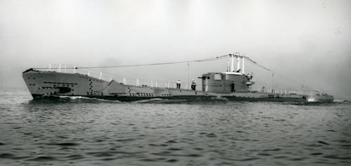
When HMS Alliance was first commissioned she had a low conning tower, anti-aircraft guns and a 4”gun mounted at the front of the conning tower. All these features were typical for a submarine of this period. However, the role of the submarine changed in the post war period: the main purpose of submarines became hunting other enemy submarines. In order to carry out this role submarines were designed to be faster and quieter when under-water. In 1958 Alliance underwent modernisation work that saw the conning tower and guns replaced by a fin that completely covered her periscopes when dived. Both these alterations made Alliance more streamlined and better equipped for submarine warfare in the Cold War era.
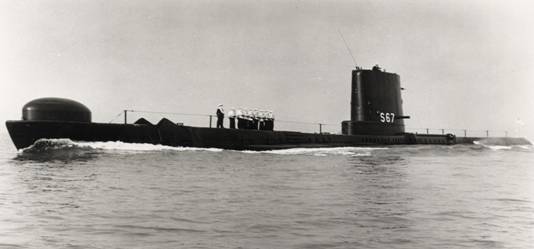
Nuclear submarine fire left Russia on ‘brink of the biggest catastrophe since the time of Chernobyl’ in December.
Russia came close to nuclear disaster in late December when a blaze engulfed a nuclear-powered submarine carrying atomic weapons, a leading Russian magazine reported, contradicting official assurances that it was not armed. Russian officials said at the time that all nuclear weapons aboard the Yekaterinburg nuclear submarine had been unloaded well before a fire engulfed the 167-metre vessel and there had been no risk of a radiation leak. But the respected Vlast weekly magazine quoted several sources in the Russian navy as saying that throughout the fire on December 29 the submarine was carrying 16 R-29 intercontinental ballistic missiles, each armed with four nuclear warheads.
“Russia, for a day, was on the brink of the biggest catastrophe since the time of Chernobyl,” Vlast reported. The 1986 disaster in modern-day Ukraine is regarded as the world’s worst nuclear accident. Neither the Russian Defence Ministry nor the office of Deputy Prime Minister Dmitry Rogozin, who has responsibility for military matters, would immediately comment on the report. A spokesman for the navy could not be contacted.
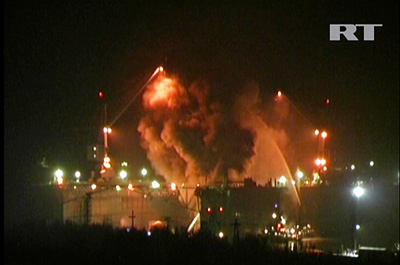
The fire started when welding sparks ignited wooden scaffolding around the 18,200-tonne submarine at the Roslyakovo docks, 1,500 km (900 miles) north of Moscow and one of the main shipyards used by Russia’s northern fleet. The rubber covering of the submarine then caught fire, sending flames and black smoke 10 meters (30 feet) above the stricken vessel. Firemen battled the blaze for a day and a night before partially sinking the submarine to douse the flames, according to media reports. Vlast reported that immediately after the fire the Yekaterinburg sailed to the navy’s weapons store, an unusual trip for a damaged submarine supposedly carrying no weapons and casting doubt on assurances that it was not armed. “K-84 was in dock with rockets and torpedoes on board,” the magazine said, adding that apart from the nuclear weapons the submarine was carrying torpedoes and mines as well as its two nuclear reactors. The magazine said that if one of the torpedoes had exploded it could have threatened the nuclear missiles, leading to an extremely dangerous nuclear accident. Media reports of what happened at the time of the fire were contradictory and foreign journalists were unable to gain access to the high security zone. Russia’s worst post-Soviet submarine disaster was in August 2000 when the nuclear submarine Kursk sank in the Barents Sea killing all 118 crewmen aboard.
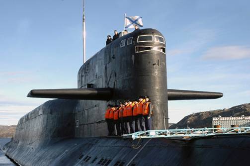
The crew of Russia's nuclear-powered submarine Yekaterinburg line up on its deck as it returns to Gadjiyevo base in Murmansk region on Sept. 26, 2006.
Worst nuclear submarine incidents.
Some of the major accidents and incidents involving nuclear submarines in the 21st century:
- August 12, 2000 – The Russian Oscar-II class submarine Kursk with 118 crew members sinks to the bottom of the Barents Sea after an explosion triggered a raging fire in the vessel. A 2002 report said a torpedo fuel leak caused the massive explosion.
- February 9, 2001 – The nuclear submarine USS Greeneville’s rudder tears through the Ehime Maru’s lower deck during a fast surface maneuver, sinking the Japanese fishing boat within minutes. Nine people aboard die, including students and instructors in commercial fishing. Twenty-six people are rescued.
- August 30, 2003 – A Russian nuclear-powered submarine, the K-159 sinks as it is being transported through the Barents Sea on its way to a scrapyard at the port of Polyarny. Nine out of the 10 crew aboard die.
- January 9, 2005 – One crewman dies after the U.S. nuclear submarine San Francisco runs aground off Guam in the Pacific Ocean. Another 23 crewmen are injured.
- August 1, 2005 – One worker is killed and another seriously injured in an explosion on a decommissioned Victor-III class Russian nuclear submarine docked in the northern shipyard of Severodvinsk for dismantling.
- September 6, 2006 – A fire on board a Viktor-III class Russian navy submarine kills two crew. The St Daniel of Moscow was moored in the Barents sea, north of the Rybachiy peninsula near Russia’s border with Finland when it caught fire.
- March 21, 2007 – Two British soldiers die and another is injured on HMS Tireless during an exercise in the Arctic.
- November 8, 2008 – More than 20 people are killed and another 21 injured by toxic gas when a fire safety system misfires on Russia’s Nerpa nuclear submarine during trials in the Sea of Japan.
- April 8, 2011 – Two Royal Navy personnel are shot, one fatally, on board the Astute, a British nuclear submarine in the southern English port of Southampton. Another sailor is later arrested. The 7,500-tonne vessel is the first of a new class of British nuclear-powered submarines which will be the largest and most powerful attack submarines ever built for the navy. The submarine had run aground the previous October for ten hours near the Skye Bridge and the captain was relieved of his command the next month.
- December 30, 2011 – A fire aboard the 167-metre (550 feet) 18,200-tonne Yekaterinburg is extinguished after blazing for nearly a full day and night. Nine people are injured. The submarine is based at the Roslyakovo dock, one of the main dockyards of Russia’s Northern Fleet, 1,500 km (900 miles) north of Moscow.
Ula Class Submarines, Norway.
The Royal Norwegian Navy (RNoN) operates Ula Class diesel electric submarines. Six subs were designed and built by Germany based Thyssen Nordseewerke (TKMS) between 1989 and 1992. Ula Class was jointly developed by Norway and Germany. The German designation for the submarine is U-Boot-Klasse 210. The hull sections were built in Norway and assembled in Germany. The first submarine in class, KNM Ula (S-300), was launched in July 1988 and commissioned in April 1989.
KNM Utsira (S-301) was launched in November 1991 and commissioned in April 1992. KNM Utstein (S-302) was launched in April 1991 and commissioned in November 1991. KNM Utvaer (S-303) was launched in April 1990 and commissioned in November 1990. KNM Uthaug (S-304) was launched in October 1990 and commissioned in May 1991. The last ship in class, KNM Uredd (S-305), was launched in September 1989 and commissioned in to the RNoN in May 1990. Ula Class submarines are one of the quieter and more manoeuvrable subs in the world. The submarine can be hardly detected by enemy surface vessels due to its trimmed profile. It has a length of 59m, beam of 5.4m and a draft of 4.6m. The surfaced and submerged displacements of the submarine are 1,040t and 1,150t respectively. The submarine can accommodate 21 crew members.
Ula Class submarine upgrades.
"Ula Class was jointly developed by Norway and Germany. The German designation for the submarine is U-Boot-Klasse 210." The Ula Class upgrade programme commenced in 2006. The entire fleet will be upgraded with new combat systems, periscopes, navigation and sensor systems, communications equipment, electronic warfare systems, steering controls and engines by 2015. About 60 systems will be modernised on each submarine during the upgrade. Howaldtswerke-Deutsche Werft (HDW) will provide engineering assistance throughout the upgrade programme. The upgrades will ensure the Ula Class submarines remain in service until 2020. In December 2010, Kongsberg Defence & Aerospace was contracted to supply navigation and radar systems for the Ula Class submarines. In October 2011, Saab received a SEK105m ($15m) contract from Norwegian Defence Logistics Organisation to upgrade steering control consoles of the Ula Class submarines.
Command and control systems on the Ula Class diesel electric submarines.
The Konsberg MSI-90U command and weapons control system of Ula is based on a high-capacity databus and a distributed computer system. The system uses a local area network or point-to-point connections to communicate with the onboard sensors, weapons and navigation system. The multifunction operator console provides tactical information based on the data available from sensors and other sources. The MSI-90U is also operational with the Type U212A submarines of Germany and Italy. In May 2008, the Norwegian Defence Logistics Organisation placed an order with Kongsberg Defence & Aerospace for the delivery of a new combat system integration infrastructure, passive sonar system, echo sounder systems and an upgraded tactical simulator for six Ula Class submarines. Delivery is scheduled to conclude by mid 2012.
Torpedoes, sensor / radar systems and countermeasures of the Norwegian subs.
Ula Class is fitted with eight 533mm bow torpedo tubes for launching Atlas Elektronik DM2A3 torpedoes. The DM2A3 can carry a 260kg warhead up to a maximum range of 28,000m. "The Royal Norwegian Navy (RNoN) operates Ula Class diesel electric submarines." The existing sonar systems are being replaced with Konsberg submarine sonar processing suite which includes passive sonar, passive ranging sonar, intercept sonar, towed array sonar and flank array sonar. The surface search radar fitted is the Kelvin Hughes 1007. In December 2010, ITT Corporation was awarded a contract by the Norwegian Defence Logistics Organisation to supply six tactical radar electronic support measures (ESM) and surveillance systems for the Ula Class submarines. The ES-3701 precision ESM system from ITT performs automatic threat detection and warning by monitoring electromagnetic energy generated by other vessels or objects. The system provides accurate outcomes while operating in high density environments.
Propulsion.
The Ula Class is powered by diesel-electric propulsion system consisting of two improved MTU 12V 396 diesel engines and an electric motor. The power plant generates a total power output of 6,000shp. The propulsion system provides a surfaced speed of 11kt and submerged speed of 23k.
Diesel Submarine Keel Laid Down in Russian Yard.

The Admiralty Shipyard in St. Petersburg lays down a new Varshavyanka class diesel-electric submarine for Russia’s Black Sea Fleet. Stary Oskol will be the third in a series of six Varshavyanka class submarines which are expected to join the fleet by 2016. The first sub, the Novorossiisk, was laid down in August 2010, followed by Rostov-on-Don in November 2011. The Varshavyanka class is an improved version of the Kilo class submarines, featuring advanced “stealth” technology, extended combat range and ability to strike land, surface and underwater targets. These submarines are mainly intended for anti-shipping and anti-submarine missions in relatively shallow waters. The vessels, crewed by 52 submariners, have an underwater speed of 20 knots with the ability to patrol for 45 days. They are armed with 18 torpedoes and eight surface-to-air missiles.
Submarine Dives Again 18 Years Later.
Ukraine’s only submarine, the 'Zaporozhye', underwent first-stage sea trials including running submerged after major refit. The boat was submerged in the Black Sea for the first time in 18 years during the trial, Fleet Commander Vice Admiral Yury Ilyin said. A Soviet-era Foxtrot class (Project 641) diesel-electric submarine, Zaporozhye was laid up at a dock in Sevastopol for years before its refit. Though the submarine was built 40 years ago, it has been upgraded with new equipment. Russian engineers repaired and serviced the submarine and a new crew of Ukrainian submariners was trained at Russian naval bases. Russia, Bulgaria, and Romania also have submarines based in the Black Sea.
Navy probing submarine accident.
The SA Navy board of inquiry is investigating an incident last month that saw the diesel-electric attack submarine SAS Queen Modjadji I hit the ocean floor while conducting training exercises between Port Elizabeth and Durban. Part of the bow section of the outer hull was damaged.
The Sunday Times photographed the German-built Type 209 1400MOD submarine undergoing repairs in Simon's Town this week. The paper yesterday said the SA Navy Saturday acknowledged she had been damaged during a "training exercise". “This means that all three submarines - meant to police the oceans - are presently undergoing repairs and maintenance,” the Sunday Times said. The SAS Manthatisi, the first of the country's submarines acquired in a controversial multibillion-rand arms deal, has been in the dry dock since 2007 after a series of mishaps, including crashing into a quay and damaging her steering mechanism. Then a power cable was incorrectly plugged into her shore power-supply system, causing damage. The vessel's propulsion batteries, which cost R35-million, are being replaced. The SAS Charlotte Maxeke is also undergoing "routine maintenance", according to navy chief director maritime strategy Rear Admiral Bernhard Teuteberg. "We did a proper technical investigation and now we have convened a board of inquiry to look at all the procedures to see whether there is something we can learn from this. As soon as that is completed, we will adapt our procedures of conducting this specific set of safety drills." The accident reportedly took place during a safety drill involving the boat's hydraulic system. She surfaced after impact and continued sailing to Durban, where she was checked by a team of divers and afterwards returned to Cape Town, the Sunday Times said.
The admiral downplayed the latest incident, and insisted the submarine could be back in the water "within days". However, he said repair work to the vessel's bow would be completed later in the month. The paper observes the collision comes three months after the Queen Modjadji welcomed a new commander, Commander Handsome Thamsanqa Matsane (he took command in April). Teuteberg told the paper he flew to Simon's Town naval base to inspect the damaged submarine. "I personally went down from Pretoria to Simon's Town to go and have a look at the submarine and speak to the crew. When I initially heard about [the accident], I thought, 'Hell, this must have been a bump' ... I spoke to the captain and the officers. Some of them said they didn't even notice the bump." The vessel's “black boxes” - which keep a record of her movements and functioning of her equipment - would help determine the cause of the incident, he said. Naval sources and SA defence analyst Helmoed-Römer Heitman have observed that accidents and incidents involving submarines are not uncommon. The Canadian submarine HMCS Corner Brook was extensively damaged last year June off Vancouver in a similar grounding. Other recent accidents involving submarines include a fire aboard a Russian nuclear submarine in port at Murmansk in December and the HMS Astute, lead-ship of a new class of British nuclear attack submarines running aground off the Isle of Skye in October. She was undergoing sea trials at the time.
Russian Sub Had Nukes During December Fire.
A fire at a drydocked Russian nuclear submarine in December could have sparked a radiation disaster because it was carrying nuclear-tipped ballistic missiles and other weapons, despite official statements to the contrary, a Russian news magazine reported Monday. The respected Kommersant Vlast said the fire aboard the Yekaterinburg could have triggered powerful explosions that would have destroyed the submarine and scattered radioactive material around a large area. When the fire erupted on Dec. 29, Russia's Defense Ministry said all weapons had been unloaded before the submarine was moved to a drydock for repairs at the Roslyakovo shipyard in the Murmansk region. The ministry declined immediate comment on the magazine's claim. It took hundreds of emergency workers more than 20 hours to extinguish the massive blaze that shot orange flames up to 66 feet (20 meters) into the air. The Defense Ministry said an unspecified number of crew members remained inside the sub during the fire and that seven crewmen were hospitalized after inhaling carbon monoxide fumes from the blaze. The fire, which authorities later blamed on a breach in safety regulations, erupted at wooden scaffolding around the sub and quickly engulfed the vessel's rubber-coated outer hull. With the sub's hydraulic systems incapacitated, the crew had to manually remove heavy torpedoes from tubes in the bow to prevent them from exploding as temperatures were rising quickly. The magazine said that an explosion of torpedoes, each carrying 660 pounds (300 kilograms) of TNT would likely have destroyed the bow and could have triggered a blast of nuclear-tipped missiles in the midsection and the vessel's two nuclear reactors. "Russia was a step away from the largest catastrophe since Chernobyl," Komersant Vlast said, referring to the 1986 explosion at a nuclear power plant in then-Soviet Ukraine. The magazine said that weapons are normally removed from submarines before repairs, but the navy wanted to save time on a lengthy procedure to unload the missiles and torpedoes. It said the repairs were supposed to be relatively minor and the Northern Fleet wanted the Yekaterinburg to be quickly back to service.
Mall submarines are sunk.
West Edmonton Mall's fleet of submarines is heading to the scrap yard. Divers and technicians have begun work to dismantle and to cut up the four mothballed tourist attractions, a process expected to take 30 daysThe four Polaris subs were once part of a ride operated by the mall. They carried up to 24 people at a time on a 20-to 30-minute ride around the indoor lake inside North America's largest mallSince making their last voyage in June 2005, the submarines - once touted as a fleet larger than the Canadian Navy's - have spent years rusting on their underwater track.After the 38-tonne aluminum and lead subs are cut up into pieces by divers using high-powered saws, the metal will be recycled. It's one of the oddest jobs for North Vancouver-based All Sea Enterprises, the company handling the sub demolition, said Matt Bone, senior surface engineer.It would be the most unusual because we've never worked in an environment so friendly - a shop-ping centre," said Bone, laughing. The mall, which is undergoing a facelift, decided the decommissioned subs had to go.We ceased operating the submarine rides because we weren't happy with the quality of the attraction," said West Edmonton Mall general manager Stacey Claffey. "We spent time looking at how we might be able to use the sub-marines again, but there weren't any options that could meet the standards we want in an attraction, most importantly, providing a unique and exciting experience. "The reality is that now the sub-marines are old and deteriorating, they no longer meet the standards for such vessels, and they do not add excitement to the lake. "Our revitalization plans include all areas of the shopping centre and the removal of the submarines will certainly help us identify a variety of options for Deep Sea Adventure Lake and area," Claffey said.
Iranian Navy Receives 3 Ghadir-Class Submarines.
The Iranian Navy expanded the fleet of its submarines after it received three more Ghadir-class submarines today, Iranian Army's Navy Commander Rear Admiral Habibollah Sayyari announced on Saturday. |
|
Speaking to reporters in a press conference here in Tehran on Saturday, the Navy commander underlined that all parts of the submarines have been designed and manufactured by Iranian experts. "All parts of these submarines, including their body and their advanced radar equipment and defense systems, have been designed and manufactured by our country's defense experts and with the help of the Defense Ministry," he said. Iranian commanders had earlier said that Ghadir-class submarines boosted the Navy's capability in defending the country's territorial waters. The submarine has been designed and manufactured according to the geographical and climate conditions and specifications of Iranian waters, according to military experts. Last August Iran launched four light and advanced submarines. The Ghadir-class submarines, made by the Defense Ministry's Marine Industries, officially joined Iran's naval fleet in an official ceremony attended by Iranian Defense Minister Brigadier General Ahmad Vahidi and Rear Admiral Sayyari. Iran announced in June 2009 that a home-made submarine, named Ghadir 948, had joined the naval brigade of the first naval zone. In November 2009, Iran announced that its first domestically built Ghadir class submarine launched operation. The Iranian military officials said that the submarine can easily evade detection as it is equipped with sonar-evading technology and can fire missiles and torpedoes simultaneously.
Greenpeace ship, submarines to monitor Arctic drilling.
|
Greenpeace plans on deploying two submarines to keep tabs on Royal Dutch Shell when the oil company starts drilling in the Arctic, which could begin as soon as next month. The subs, a two-person and a one-person craft, are currently on board the Greenpeace ship Esperanza, docked in Seattle on a temporary stop.The Esperanza plans on shadowing Shell's drilling fleet, also docked in Seattle, when he fleet leaves for Arctic waters. Shell is waiting for the last batch of federal permits, expected any day, before deploying its ships. Once the operation begins, Shell plans on drilling up to five exploratory wells in Arctic waters -- three about 70 miles off the Alaskan coast in the Chukchi Sea, and two about 17 miles off Alaska's North Slope in the Beaufort Sea. They will be some of the first wells drilled in Arctic waters, and have touched off a debate about whether the country should be exploring for oil in the sensitive Arctic environment. Greenpeace plans on deploying the subs at the Chukchi site and will monitor the Beaufort site by ship. "We want to be there so we can see if anything goes wrong," said John Hocevar, oceans campaign director for Greenpeace, who will pilot one of the subs. Due to its penchant for disrupting certain industrial operations, a federal judge has barred Greenpeace from getting within 1 mile of Shell's drill ships. But Hocevar said that shouldn't be a problem -- any oil leaks or other trouble should be able to be well documented from even a mile away. He said the submarines will also take a look at the sea floor, taking inventory of the abundant starfish, mollusks, and sponges that are thought to live in the region. It will be the first time this part of the ocean has been explored by manned submersibles. On board the Esperanza, Greenpeace will monitor the impact the drilling is having on the larger wildlife in the region, which include whales, polar bears and walruses. Shell did not appear phased by Greenpeace's plans. "Once their data is analyzed and peer reviewed, it could perhaps be added to the decades of credible science Shell has already gathered in the Arctic," said Kelly op de Weegh, a company spokeswoman. Hocevar would prefer the drilling didn't happen at all, and is worried that if Shell hits oil it will touch off a resource race in the sensitive Arctic region. Unlike the warm Gulf of Mexico, the Arctic's frigid waters are not thought to break down oil very quickly. Oil from the Exxon Valdez spill is said to remain on shore just below the surface, and that spill happened over 20 years ago. Greenpeace and other critics of Arctic drilling say Shell is woefully unprepared to deal with an oil spill in Arctic waters.
150 New Submarines to be Built until 2021.
The military submarine market is expected to continue growing in a modest pace through the second decade of the 21st century, as naval forces are inducting modern, more capable submarines, designed for extended operational missions at sea. Along with the growth of the submarine fleets, there is a growing interest in combat systems, sensors, defense systems countermeasures, as well as the means for integrating submarines with surface and joint operations, the ‘ICD global submarine market report 2011-2012‘ indicated. Submarines form an essential core of today’s naval fleets as a result of their flexible mission capabilities and ability to complement other strategic resources. Worldwide, 41 countries possess submarine capability and together operate 450 submarines. Most of these nations are modernizing their fleets or increasing them as a result of changing security situations. A total of 155 submarines are to be procured over the forecast period, costing US$188.8 billion.
North America is set to constitute 46.27% of the global submarine market during the forecast period, followed by Europe with 24.48%, Asia with 24.35% and Latin America at 4.55%. With the dramatic growth of major Asian fleets, Asia-Pacific is expected to significantly impact the submarine market throughout this decade. The rise of regional powers with ambitions for power projection coupled with a growing sense of hostility and a resulting arms race in Asia-Pacific is driving the submarine market. The need to replace a Soviet era submarine fleet, rising maritime threats such as piracy, transnational terrorism and growing demands to protect sea lanes and communication lines are also important factors behind the desire for a strong submarine capability.
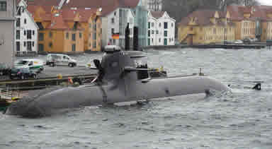
U-212 class submarine U-34 (S-184) at Bremen, 2007.
Submarines by Category. 102 conventional Submarine Hunter Killer types (also called attack submarines – SSK), 37 nuclear-powered attack submarines (SSN) and 16 Nuclear powered Ballistic Missile carrying Submarines (SSBN) are to be built across the globe over the forecast period. Major markets for SSKs include Brazil, India, Turkey and Vietnam, which have planned procurements in place. The SSN market is dominated by the US, which is planning to buy 21 SSN’s across the forecast period. A total of 16 SSBNs are planned to be procured during the forecast period at a value of US$57.1 billion, which includes the cost of R&D of the US SSBN (X) and the UK’s SSBN (R) programs.
Evolving technology and changing mission profiles
The improvements in underwater sensor and propulsion technologies have resulted in extended underwater endurance, as in the case of diesel electric submarines through the aid of an Air Independent Propulsion system. This has broadened the operational scope of today’s submarines, extending its mission profile to include enhanced ISR operations and Special Forces insertion and extraction. Developments in sensor and stealth technology have resulted in the boats undertaking covert operations near enemy territory and in littorals with near impunity to enemy sensors.
Navies Opt for Improved Capabilities to Cope with Force Reduction, Budget Cuts
The reduction in defense budgets in the Western world combined with changes in the global strategic security situation and the advent of sophisticated technology has brought about an immense change to the submarine market. Rising economic powers such as China, Brazil and India and their neighbors will increase expenditure on acquiring submarines and on developing the necessary submarine industrial base. The overall reduction in submarine orders in the West have forced the industry to reinvent the production process, turning to modular production processes and cutting down on manufacturing cost and time. The increasing cost of technology development and its rapidly changing nature has driven the submarine industrial base to adapt to modular and flexible systems architecture, which has long term benefits such as ease of upgrade installation and through life support. It also helps to easily switch between various mission profiles by swapping modules. Varying mission profiles has in turn resulted in the adaptation of a flexible payload to effectively deal with varying threats.
Shifts in submarine procurement patterns to stimulate collaboration and consolidation
The above factors have led to increasing collaboration amongst the submarine industrial base (SIB) present within a country. The decrease in demand in the West, which has a matured SIB, and the increasing demand from the rest of the world, which has limited industrial capability but stable financial growth, has resulted in cross border consolidation. The political will and limited restrictions in transferring sensitive technology have also led to growing license production through technology transfer agreements, a trend that is expected to increase during the forecast period.
Kockums Embarks on a Stealth Sub for the Swedish Navy
The Swedish Government has approved initiation of the design phase for the A26, a new generation submarines slated to replace the Gotland class submarines currently in service with the Royal Swedish Navy. The Swedish shipbuilder Kockums, that have specialized in maritime stealth designs, will be responsible for the new design, that will also have stealth capabilities.
The new 1400 ton diesel-electric powered sub will be designed primarily for littoral operations and, with Kockums Stirling Air Independent Propulsion (AIP) providing it with long endurance, characteristic with ocean-going capabilities. The Stirling system, together with a set of balanced underwater signature properties, will make the A26 submarine stealthy and difficult to detect. It will also be higly invulnerable to underwater explosions (mines, depth charges) through verified shock resistance design. The new design includes an auxiliary payload capability with a flexible payload lock system, in addition to the conventional torpedo tubes, enabling the submarine to carry and deploy unmanned underwater vehicles or other oversized payloads for different missions. The submarine will also be prepared for network connectivity. Kockums embarked on the concept for the next generation submarine in December 2007 and is currently negotiating the A26 design contract with the Swedish Defence Materiel Administration (FMV). The Swedish Navy plans to procure five submarines of the new class. Norway has also expressed interest in the new submarine. Earlier in the 2000s Sweden, Norway and Denmark participated in a joint development and procurement of the Viking class ‘Nordic Submarine’ program which was later shelved due to the cancellation of the Danish submarine force.
DCNS Highlights Scorpene, Andrasta SSN Submarines.
DCNS is a major supplier of surface vessels and submarines in the Latin America region and, specifically Brazil. Since 2008, the Brazilian Navy and DCNS embarked on a large scale program to design and construct of four Scorpene type conventional-propulsion submarines, under a technology transfer agreement in which the French designer will provide the technical assistance for the design and construction of the submarine, as well as the non-nuclear part of the first Brazilian nuclear-powered submarine. DCNS also provides support services for the construction of a new naval base
and a shipyard to support these vessels.

A cutaway model showing the cutaway of the Scorpene with Andrasta at the background.
At LAAD 2011 DCNS is displaying models of its compact submarine, designed for operation in coastal waters, a theatre of growing importance to all maritime nations. Andrasta is a direct descendant of the Scorpene already selected by Brazil. According to the designers, Andrasta combines a state-of-the-art design with stealth, agility and power. The company highlights here the F21 heavyweight torpedo, designed to replace the French Navy’s current-generation F17 mod2 torpedo carried by its SSBN (Ship Submersible Ballistic Nuclear) ballistic missile submarine fleet and has also been selected for the next-generation Barracuda-type SSN fleet. The F21 is being developed in response to new and emerging operational challenges to offer the host submarine unrivalled dominance. Its discretion, range and fire power will give it an unrivalled tactical advantage over all adversaries. The new torpedo is designed to knock out enemy surface vessels and submarines. As for self-protection of the submarines, DCNS highlights the Contralto-S torpedo countermeasures suite for submarines, designed to defeat latest-generation torpedoes by using acoustic decoys employing ‘confusion/dilution’ principle. Contralto-S is designed for all types of submarines and can be incorporated into new-build designs or added to existing boats as part of a refit or modernization program. The Brazilian Navy has already selected the Contralto-S for its new class of submarines, following the French Navy use of the system as part of the Nemesis program protecting its conventional attack submarines. DCNS also highlights its expertise in integrating submarine combat systems. The principal system is SUBTICS, which combines the submarine handling, long-range navigation and weapons control, including torpedoes, anti-ship missile, counter-measures, and land-attack capability. As a fully-integrated system, all functions are operated from multi-function common consoles and its open architecture and modularity guarantee that the system can be adapted to every type of submarines and configured according to operational requirements.
Deep Submergence Unit Shifts ISIC, Changes Name.
During of an office call at CSS-11, Capt. Brian Howes, Commodore of DEVRON-5 turned over ISIC responsibilities to Capt. Thomas Ishee, Commodore of CSS-11. In addition to the ISIC shift, Deep Submergence Unit officially changed its name to Undersea Rescue Command (URC).
Based on periodic reviews of Submarine Squadron missions, functions and tasks, the decision was made to shift ISIC responsibility from DEVRON-5 TO CSS-11. "This shift allows more responsive and consistent support and oversight of submarine rescue system operations and maintenance by the entire staff of Submarine Squadron 11," said Howes. "This responsiveness is driven by the co-location of Undersea Rescue Command and Submarine Squadron 11 in San Diego." Staffed with over 130 active duty, Reserve, contractor, and civilian personnel, URC provides a lifeline for distressed submarines worldwide. The official name changed from DSU to URC because that name better represents the mission of submarine rescue. "My mission is to provide the U.S. Navy with a submarine rescue capability, worldwide deployable," said Cmdr. David Lemly, commanding officer of URC. "That mission hasn't changed and that is our primary mission here". URC joins more than 100 officers and 1,200 enlisted personnel who comprise CSS-11, which now consists of URC, six Los Angeles-class nuclear-powered attack submarines, three torpedo retrievers, and a floating dry-dock. The squadron staff is responsible for providing training, material and personnel readiness support.
Israel and Berlin sign contract for sixth submarine.
Israel and Germany signed a contract a few weeks ago finalizing the sale of a sixth Dolphinclass submarine to the Israel Navy.The Defense Ministry initiated talks with Germany last year about buying a sixth submarine but Chancellor Angela Merkel’s government initially balked when Israel asked that it underwrite part of the cost. In late November, though, Germany announced that it had approved the deal and that it would pay for part of the vessel. Christian Schmidt, secretary of state for defense, told the Post that the contract was signed a few weeks ago and that Germany had agreed to subsidize its cost. Calling Israel a “preferred customer,” Schmidt said the sale of the submarine was a demonstration of his country’s commitment to Israel’s security. “The security of the State of Israel is a German concern and this will not change,” he said during a visit to Israel during which he met with Israeli diplomatic and defense officials and attended the Herzliya Conference. Schmidt dismissed media reports that claimed Merkel had considered canceling the deal in response to Israeli construction in Jerusalem’s Gilo neighborhood, over the Green Line. “We are good friends and sometimes we need to talk about things that we do not think should be done regarding the settlement policy,” Schmidt said. “We do not see this as a linkage [to the submarine issue] but as a part of friendly talks.” Israel already has three Dolphinclass submarines and two are currently under construction in Germany with delivery expected later this year. According to foreign reports, Israel’s submarines have a second-strike capability and carry cruise missiles armed with nuclear warheads. Germany donated the first two submarines after the First Gulf War and split the cost of the third with Israel. The three submarines currently in the navy's possession employ a diesel-electric propulsion system, which requires them to resurface frequently to recharge their batteries. The submarines under construction will be fitted with a new propulsion system combining a conventional diesel lead-acid battery system and an air-independent propulsion system used for slow, silent cruising, with fuel cells for oxygen and hydrogen storage. Schmidt said that Germany was looking to increase its defense cooperation with Israel and was specifically interested in learning from the IDF about training and military doctrine. He said that Germany was also considering buying the Heron TP long-range unmanned aerial vehicle later this decade to replace the Heron 1 it is operating in Afghanistan. Both UAVs are manufactured by Israel Aerospace Industries.
Former defense minister was also to blame, German court says.
Two former managers of Ferrostaal AG, a German-based industrial services company, have been convicted of paying bribes for contracts in Greece and Portugal and received suspended prison terms of two years. The firm has been fined 140 million euros.The president of the Munich court on Tuesday blamed Greece's defense minister at the time, Akis Tsochatzopoulos, without naming him. Tsochatzopoulos has been indicted for accepting bribes for the purchase of submarines.“Submarines are purchased by politicians, not by private individuals,” Skai quoted the court president as saying.The German company worked with many different intermediaries and aides to have access to Greece's defense ministry, the court said, while at least a third of the money went to officials at the ministry.Ferrostaal said at the beginning of the trial on December 15 that it was willing to pay the fine, which was the result of «intensive negotiations.” The company said in a statement Tuesday that it would bear the consequences and pay the fine.The two former company managers were identified only as Johann- Friedrich Ha., 73, and Hans-Dieter Mue., 73. Ha. was also fined 36,000 euros and must pay 30,000 euros to charities to have the term suspended. Mue. was fined 18,000 euros and must pay 22,000 to charities, according to the statement.A statement by the ultranationalist LAOS party, which is a member of Greece's provisional administration, said developments had vindicated the party's position.“Those who paid bribes have been put to jail in their country. Those who took bribes in Greece have gotten away with it,” it said.“It's time we found out what officials inside the defense ministry received the 21 million euro kickback described in the court ruling,” the party said, urging prime minister Lucas Papademos to ask Berlin for more details on the case.A preliminary probe into the “origin of wealth” declarations submitted by politicians for 2009 and posted on Parliament’s website on Tuesday only found irregularities with Tsochatzopoulos's declaration.
South Korea And The Little subs.
December 2, 2011: South Korea  is replacing two elderly 250 ton Italian mini-submarines (from the 1980s) with the locally designed KSS 500A. This is a 510 ton, 37 meter (115 foot) long, 4.5 meter (14 foot) diameter boat. It cruises at 12 kilometers an hour (for up to 21 days) and can hit a top speed of about 36 kilometers an hour. Maximum dive depth is 250 meters (775 feet). Meant for coastal operations, the 500A would be useful against North Korea
 or even China or Japan. Each 500A can carry two heavy and four light torpedoes. There is also space for some mines and vertical launched missiles. The boat also has accommodations for 14 commandos and the ability of them to use scuba gear to leave the sub while submerged. The submarines crew consists of ten sailors, and all power is carried in lithium-ion batteries. South Korea
 plans to build five of these boats. Design work began three years ago, and construction is to begin next year.
Taiwan Brings It All Back Home
For over a decade, Taiwan has been trying to buy new submarines to replace its existing, and rapidly aging boats. The latest solution is to build the boats in Taiwan. The rumors coming out of European shipyards is that Taiwan is quietly arranging to have European submarine building experts accept contracts to discreetly work in a Taiwanese shipyard for a while. Meanwhile, some European builders have agreed to train Taiwanese welders in the specialized type of welding used on submarines. Other negotiations are under way to purchase a wide array of specialized components needed for diesel-electric submarines. Some shopping has been done in the United States, but the Americans have only built nuclear subs for the past half century, and the best technology for diesel-electric sub construction is now found in Western Europe. Taiwan is running out of time to find replacements for its aging submarine force. Taiwan currently has four boats. Two are 70 year old American Guppy class subs. These are used only for training, and are increasingly difficult and expensive to maintain. The two Hailung class subs were built in Holland and entered service in 1986. These 2,500 ton boats are armed with twenty torpedoes and Harpoon missiles (launched from the torpedo tubes.) But there's a new problem as well, because of plummeting morale among the 200 sailors who run these boats. Years of delays in obtaining new subs, and dim prospects of ever getting them, discourages qualified young sailors from volunteering for the submarine service, and many old hands are retiring as soon as they are eligible. The search for a shipyard willing to build, for Taiwan, eight diesel-electric submarines failed. None of the European shipyards that specialize in this sort of thing would do it, as they feared economic retaliation from China. The United States had not built a diesel electric sub since the 1950s. Getting an American shipyard up to speed on building diesel electric subs would be expensive, and no one is sure exactly how expensive. Moreover, the uncertainty of how much it might cost is scaring many Taiwan supporters in the U.S. government. Alternative solutions were investigated. Publicly, Taiwan says it wants the subs for anti-submarine work. But it's been pointed out that there are cheaper and more effective anti-sub capabilities available via helicopters, aircraft and UAVs. What is left unsaid is that the subs could also be used to shut down China's ports, crippling the economy and causing lots of political problems for China's leaders. It's also possible to shut the ports without using subs (air dropped naval mines, or just threatening to attack any merchant ship entering Chinese waters), but nothing does this sort of thing as effectively as a submarine, especially a very quiet diesel-electric sub. Ideally, Taiwan wants eight new diesel-electric boats, preferably with AIP (air independent propulsion). This would drive the price up to nearly a billion dollars a boat. In addition to building them in Taiwan, there are two other potential sources. One prospect was India, which has become quite alarmed at China's growing naval strength. India is building its own subs, with six French Scorpene class diesel-electric submarines under construction there. The Scorpene is a very modern design (and the result of cooperation between a French and a Spanish firm) that displace 1,700 tons, and with a crew of 32. It has six 533mm (21 inch) torpedo tubes, and carries 18 torpedoes and/or missiles. It is equipped with an AIP. With well-trained crews, Scorpenes can get close to just about any surface ship, no matter how good the defender's anti-submarine defenses are. But it's the AIP that makes these boats real killers. Without AIP, subs spend most of their time just below surface, using their diesel engines (via a snorkel device that breaks the surface to take in air, and get rid of the engine exhaust.) Snorkels can be spotted by modern maritime patrol aircraft, and both nations are getting more of these. India is supposed to get its first Scorpene in 2015, with one a year after that. Only the last three will have AIP. The price of the contract is quoted as $300 million for each boat. That could include AIP, because the boats are being built in Indian yards, which have much lower costs. European built AIP boats go for about half a billion dollars each. Typically, AIP adds about $100 million to the cost of a sub. But there have been construction and management problems in the Indian shipyards. So the schedule, and ultimate costs, is uncertain. Since the Scorpenes are being built with Spanish and French technology, China could still pressure those nations to forbid India to build any of these boats for Taiwan. But India is also building nuclear subs, using Indian technology. At the moment, India is building all these nukes for their own use. But a Taiwanese order for over $10 billion worth of nuclear boats could change that. There are no active discussions with India on this matter. But the Taiwanese have approached Russia on the matter of collaborating in submarine construction. These discussions are still underway, and apparently not come to fruition. So Taiwan seems determined to build the subs locally. While European firms won't sell Taiwan submarines, they are apparently less reluctant to sell components and training. That might be enough for Taiwan to build its own.
Are Submarines the New Yachts for the Wealthy?
Some call it the final frontier. While humans have breached the limitations of land, air and space, the underwater world remains largely untouched. In addition to researchers and scientists, another group has taken an interest in the underwater unknown--the mega-rich. The race to the bottom of the sea is being led by director James Cameron and British entrepreneur Richard Branson. This week, Cameron is launching his unprecedented mission to the bottom of the Mariana Trench in the South Pacific. The "Titanic" and "Avatar" director is hoping to make the seven-mile dive as a solo venture, which no one has ever done before. The only pair to ever make it all the way down made the trip in 1960 and spent only 20 minutes at the site. Cameron hopes to spend six hours shooting footage of the dive for a National Geographic documentary, complete with 3D footage. Branson unveiled a single-person submarine in April 2011 that he said would break records by exploring the five deepest sea locations of the next two years. "More people have been to the moon than to that depth of the ocean," Bailey S. Barnard, associate editor of luxury magazine Robb Report, told ABCNews.com. The magazine for the "ultra-affluent" has written about private submarines in the past and plans to include the vessels in an upcoming "Toys of Summer" feature. "They're pretty darn cool and we'll continue to see more of an uptick in them as toys and vessels for exploration, as opposed to underwater homes," Barnard said. For those who consider sports cars, yachts, and private planes old news, private submarines may be the new accessory of choice for the wealthy, ranging from about $2 million to $90 million, depending on the model. "Most people don't have any idea what happens below the surface of the ocean," L. Bruce Jones, U.S. Submarines CEO, told ABCNews.com. "I've been doing this for 25 years and it's something that's getting more popular all the time." In addition to U.S. Submarines, Jones is CEO of four other companies including Triton Submarines, which specializes in luxury deep-diving submersibles. Depending on the model, the subs hold two to three people, dive between about 1,000-3,000 feet and cost between $2-3 million. The company sells about four or five subs every year, but Jones has seen an "awful lot of activity" in customer interest for the private vessels. Most of the interest has come from mega-yacht owners wanting to get a submarine for their boats that they can take out whenever they want, without having to go through an underwater tourism company. "They can sip champagne, sit around and see things no one else has seen," Jones said. "They love it." U.S. Submarines built one $90 million submarine that was the equivalent of an underwater yacht, complete with dining areas, kitchens and a gym. Even so, Jones does not expect submarines to become common. "I think that they're always going to be relatively unique," Jones said. "We expect to continue to accelerate to a new place in production, but I don't think it will ever become a household item." Ian Sheard, director of engineering for SEAmagine, a leading producer of two to three person submersibles, agrees with Jones. "We started in tourism and then had people asking, 'Can I have one?'" Sheard said. "[Customers] want a submarine and they want to drive it themselves." SEAmagine is currently training its latest customer to purchase one of the vessels, a sea enthusiast who plans to move his yacht and submarine all over the globe to the world's best diving spots, like Costa Rica, the Galapagos and Alaska. So, what's the draw? "It's exclusivity. People can't just go do it," Sheard said. "It's mind-blowing what you can see down there. The places you have the possibility of going are literally where no man has been before." Not everyone agrees that the crafts are the new plaything of choice for the rich and famous. "There's been an increase in the interest of submarines generated by those interested in increasing that interest," Stockton Rush, co-founder and CEO of OceanGate, told ABCNews.com. OceanGate organizes underwater expeditions, mostly for research purposes. "It doesn't take much to double sales," Rush said, when only a handful of subs are sold each year. "Any boat captain who lets his owner buy a submarine doesn't have control of his owner," Rush said. "A submarine and a yacht are a terrible combination for a couple of reasons." Subs require specialized training, dedicated space on the boat due to their bulkiness and weight and special certification to travel to certain places. "There's definitely an interest in undersea exploration and in submarines in general, but the interest is in going underwater and seeing stuff, not in owning submarines," Rush said. Rush doesn't deny the draw of the dive, which he calls a "spiritual experience" where passengers see and hear things differently than they ever have before. "All the sensory input you get, plus the emotional side…it's totally indescribable," he said. "Everyone gets passionate about the experience." And for those who happen to be both passionate and wealthy, a submarine may be just the thing they're looking for.
Jury does not award monetary damages in suit involving former Stuart submarine builder.
FORT PIERCE — After six hours of deliberating Monday, a federal jury voted not to award money damages to Dubai World Corp. or to submarine builder Herve Jaubert, who had been squaring off against the global conglomerate during a civil trial that began Feb 14.Jaubert was hired by Dubai World in 2004 to head Exomos, a subsidiary producing luxury recreational submarines in the United Arab Emirates, based on similar work he'd been doing in Stuart. But by 2008, Jaubert claimed he'd been falsely accused of theft, and threatened with prison before he secretly fled the country by sailboat to India.A former counterintelligence officer for the French government, Jaubert, 54, left the courthouse Tuesday evening without the money damages he'd hoped for, but said he was happy the trial was over."I feel relieved that none of the Dubai World accounts were true," he said outside court. "All their accusations were false, unfounded and untrue."Jaubert's legal battle with Dubai World began in 2009 when he sued the vast holding company in Martin County circuit court for fraud, false imprisonment and defamation. Dubai World and three subsidiaries, in turn, sued Jaubert and his firm Seahorse Submarines Industries in federal court, alleging breach of contract, fraudulent inducement, negative misrepresentations, breach of fiduciary duty and conversion related to a failed business venture to design and build recreational submarines.Both sides maintained different versions of the events that prompted Jaubert's brazen escape from Dubai and the subsequent lawsuits.At trial, Dubai World attorneys claimed Jaubert pocketed about $4 million in company money by overcharging for parts, padding invoices and adding improper service charges. He was also accused of racking up $31 million in debt while CEO before fleeing in 2008.Jaubert's original lawsuit was transferred to federal court after Dubai World sued him, but legal rulings in the case reduced his complaint to one count of abuse of process against Dubai World. He had claimed he was due money damages after Dubai World twice denied him access to his passport and had threatening him with prison if he didn't sign a document promising to repay millions in company cash.After court, Dubai World general counsel George Dalton said he was "extremely pleased" with the verdict."This decision totally vindicates Dubai World and the Dubai police and prosecutors of the baseless claims made by Jaubert," he said. "These decisions by judge and jury have finally ended Jaubert's two-year effort to extort millions from Dubai World with threats of negative publicity. He will find it very difficult to dupe anyone ever again."Dalton confirmed that Dubai World will not appeal the verdict.Jaubert meanwhile, said he was "disappointed" he failed to convince the jury of his claim against Dubai World for abuse of process."Because I know what happened to me," he said. "And I know what happened to others, and I know they do abuse the process."During closing arguments Monday, Dubai World attorneys characterized Jaubert as a "master manipulator" who was out to siphon millions of dollars in company money."Mr. Jaubert was not the master designer and builder of submarines that he said he was," insisted Los Angeles attorney Jon Cederberg, representing Dubai World Corp. "The only thing he designed and built ... was a web of lies, half-truths and misrepresentations that allowed him to get property he was not entitled to and ... a position he didn't deserve."Cederberg had asked the jury to award more than $539,000 in compensatory damages and suggested jurors return punitive damages against Jaubert of up to $750,000; however, both amounts were rejected by jurors, who awarded both sides nothing.But due to earlier rulings by U.S. District Judge Jose E. Martinez, Dubai World will leave with a damage award of $335,000 for a breach of contract claim against Seahorse Submarine related to two submersibles the court found that Dubai World had paid for, but Jaubert failed to deliver.That didn't seem to bother Jaubert and his Stuart attorney, William Hess, as they loaded cars with stacks of boxes after the verdict."I'm happy it's over and I'm going to leave that behind and move on and go back into the submarine business," Jaubert said, smiling. "I will be building submarines again."
SOUTH KOREA: FOUR COMPANIES FINED FOR CARTEL IN SUBMARINE PROJECT.
South Korea’s four major defense manufacturers have been fined for allegedly forming a cartel in a 2.7-trillion won (US $ 2.41 billion) project to build next generation submarines, the country’s antitrust watchdog said.
Navy expects new submarine by 2015
Jakarta: Navy chief Admiral Soeparno has said the first of three submarines built in South Korea will be finished by 2015. He said the procurement contract had been signed by officials from the Indonesian Defense Ministry and South Korea’s Daewoo Shipbuilding Marine Engineering in December.“The first submarine will be completed by 2015,” he said on the sidelines of military leaders meeting at the Indonesian Military (TNI) headquarters on Wednesday.Soeparno said the first submarine would completely be built in South Korea while the two others would be a joint production by Indonesians and South Koreans.Earlier, Deputy Defense Minister Sjafrie Sjamsoeddin said the contract mentions that there will be a transfer of technology in the construction of the submarines. “Indonesian shipbuilding company PT PAL will send 50 technicians to South Korea,” the former Jakarta military commander said. In the construction of the second submarine, he said, the Indonesian technicians are expected to have played roles.
My very own nuclear sub: The man who larks around in a killer Soviet 'Black Widow'... now docked on a river in Kent
Fifty years since President Kennedy's failed invasion of Cuba, the power of the 'Black Widow' submarine under the command of the Soviet Union is revealed for the first time.In action the 1,950 tonne submarine carried 22 nuclear tipped warheads and 53 explosive mines - and had the explosive power of the Hiroshima bomb.Now docked on the River Medway in Kent, the foxtrot submarine's torpedoes are disarmed and it is looked after by submarine man John Sutton, who is seeking investors to save her from ruin.Sutton, 46, has looked after the war machine for nine years, 'It was her job to hunt down enemy sea vessels. This weekend is her 44th birthday as she was built in Russia on the first of April 1967,' explained Mr Sutton. The class was so popular with Soviet allies that Libyan President Colonel Gadaffi bought a fleet of 11 foxtrot submarines in the 1980's - and is reported to still command several of the hunter killer submarines today.As the Soviet Union did not go to war with America she didn't see combat, but Mr Sutton explains:'She was used for patrolling the Baltic Sea and training sailors. By 1994 the submarine was decommissioned.'She was sold to a private investor and brought to the United Kingdom.'The sub has been used as a museum in London's Docklands and Folkstone but is now closed and currently undergoing refurbishment. After refurbishment its owners plan to relocate the sub and open it up again as an educational facility.Inside the maze-like inside of the submarine the iconic red stars and other symbols of the Soviet Union look the same as the day Communism fell.The 78 seamen lived in conditions so cramped they shared their sleeping area with live nuclear torpedoes and had to work 12 hour shifts every day.In a combat situation the Black Widow would have used its 6000 horsepower motors to chase down its intended prey - mainly ships and submarines of the US and allies like Great Britain.'When Russia sold the submarine it made sure that it was decommissioned so that it could not be used as a weapon of war against them,' says Mr Sutton.'It would be very expensive and at the moment there are currently no plans to do it - but with enough care and attention the Black Widow could be made fully operational and even submerge underwater again one day.' In action the 1,950 tonne submarine had the explosive power of the Hiroshima bomb. The sub has been used as a museum in London's Docklands and Folkstone, and is now in need of investors to refurbish and save her.The Black Widow had enough power in its three electric motors to remain underwater for up to three days.But these days the Black Widow cannot move under its own power and has to be towed.'She used to travel with ten of the 400 kilogram type 53 torpedoes loaded in her tubes - ready to fire at all times,' says Mr Sutton. 'Each torpedo had a range of ten miles and when fired would travel to its target at 30 miles per hour.'The Bay of Pigs Invasion of April 4 1961 was an attempt by the CIA to overthrow Castro's new Communist government. Soviet Russia rushed its fleet of nuclear armed hunter killer submarines to aid its ally, Cuba.During the conflict one of these 'foxtrot' class nuclear armed submarines was mistaken for a less. When Russia sold the submarine it was decommissioned so it could not be used as a weapon of war against them.Kennedy ordered the nuclear armed submarine to be attacked by a US warship and explosive depth charges hit the hull, damaging but not sinking it.Despite being authorised to attack the Russian submarine captain decided not to fire on the Americans - and may have avoided war between the two nuclear armed superpowers.Mr Sutton says he is now looking for people or organisations to come forward to give the sub a new home.'London's Russian community might be happy to help out. Maybe I should approach Roman Abramovich?' he jokes.
Submersible, ROV and Subsea Motors.
Submersible Motor Engineering/Silvercrest offer complete submersible electric motor rewinds, submersible motor rebuilding, electrical conversion and construction modification. Submersible Motor Engineering/Silvercrest can repair and completely rebuild the following listed motors. Alstra, Aturia, Bamsa, B. J., Elmaksan, Exodyne/EEMI, G.E., Mercury, Oddesse, Pleuger, Saer, S.M.E., Subteck, Sumo, Sun Star, U.S.
Submersible Motor Engineering/Silvercrest Repair and rewind large high voltage (500kW 6600V) submersible electric motors.
SUBMERSIBLE MOTOR ENGINEERING/SILVERCREST offer High Temperature Submersible motors in 6"to 20" frames suitable for operation in ambient of 75 Deg.C. High Voltage water filled submersible motors (300V, 4160V and 6600V). Upgraded Temperature Monitoring unit available with new improved user-friendly parameter setting.
SUBMERSIBLE MOTOR ENGINEERING ROV motors suitable for depths of 4000M.
SUBMERSIBLE MOTOR ENGINEERING/ SILVERCREST, design, manufacture, and supply, submersible electric motors for deep well submersible pumps, SUBSEA and ROV electric motors for SUBSEA equipment, submersible electric motors for sump pumps, and any special purpose submersible electric motor requirements.
SUBMERSIBLE MOTOR ENGINEERING/SILVERCREST also offer complete motor repair and rewind of all name brands of submersible motors, both water and oil filled.
Subsea Motors.
Submersible Motor Engineering/Silvercrest can supply HV HP motors up to 5,500kW, engineered to meet all your subsea operating conditions. A key design feature is the High Pressure capability, allowing our motors to operate effectively at water depths of 4000m. Our design ensures a 'uniform electric field' that minimises electrical stresses, to maximise the winding cable life. Our engineers also ensure the optimum temperature within the motor by careful selection of the internal flow pattern and external heat exchanger. All our Subsea motors have a variable speed capability. The materials of motor construction are typically 316 stainless steel, duplex, or super duplex stainless steel.
The Submersible Motor Engineering/Silvercrest motor design allows for a long trouble free operational life. Our subsea, ROV and submersible motors are available in water-filled and oil-filled construction. Extreme subsea conditions demand reliable, high quality, solutions that will not fail. We are experts in such technology and will engineer solutions for your subsea applications. We can also design and manufacture special application submersible motors for specific requirements.
Submersible Motor Engineering/Silvercrest is the world leader in submersible motor technology, enabling our customers to explore deeper underwater than ever before. High power, high voltage and high-pressure specifications are common place for many of our clients. Our submersible subsea and ROV motors are the best on the market today, offering a comprehensive choice of materials and design to underwater and ROV operators.
Submersible Motor Engineering/Silvercrest specializes in all aspects of submersible electric motor operation, performance, and design. Due to industry demand for readily available quality parts, we also rewind, repair, redesign, and machine major components of other manufacturer's motors that require repair and re-manufacture.
Testing. All our motors, motor-pump sets and HPUs are fully run-in at full load prior to shipment. A test certificate is supplied with each unit, stating all the recorded outputs (such as power input and output, temperature, pressure, flow, etc).
ROV Deep Ocean Motors.
Submersible Motor Engineering/Silvercrest has manufactured hundreds of ROV Motors for new and existing subsea vehicles, and other deep ocean applications. Submersible Motor Engineering/Silvercrest is a leading manufacturer of motors, motor-pump sets, and HPUs, for the power, and oil and gas industries.
Submersible Motor Engineering/Silvercrest offer a comprehensive range of Fluid Filled Electric Motors and Motor-Pump sets that are designed to meet the most demanding applications and environments for the energy market. Exceptional build quality is what makes our motors the first choice for many operators today. Our attention to detail and precision engineering is demonstrated at hundreds of locations worldwide.
Submersible Motor Engineering/Silvercrest motors are manufactured in Perth (WA) and supplied worldwide, providing superb performance and reliability.
Submersible Motor Engineering/Silvercrest supply motors for ROVs, Offshore Oil and Gas Installations, Offshore Platforms, Semi-submersibles, Subsea Processing operations and advanced deepwater motor technology. Our motors are designed by subsea experts, and built by some of the world’s most skilled engineers. Our client list includes some of the biggest names in the ROV, subsea, and oil and gas industry. Our subsea motors are High Power, High Voltage, High Pressure, and Fluid Filled for all deepwater applications. To meet the demands of complex subsea operating conditions, we manufacture HV HP motors up to 5,500kw (or higher). Our motor design enables the motors to operate at depths of 4000m. These parameters accommodate most subsea projects. However other motor designs and subsea solutions are available on request.
Extensive research and development experience of custom builds and project led engineering, makes Silvercrest/SME your ideal subsea partner.
ROV'S FOR IMMEDIATE SALE.
a) Hyball Rov available for sale in excellent condition, all latest circuit
boards and modifications. Extensive spare parts package included. Training
course available. Fantastic buy, a bargain.
b) Phantom DHD2 Rov for sale in very good condition and dive ready, complete with spare parts, and LARS. Standard operating depth 300m (max depth 600m). Manipulator, 2 * 500w lights fixed position, 2 * 250w linked to camera pan/tilt. Heading compass, and Depth gauge. Power requirement 230 volt, 50 Hz, 15 KVA. New 1200ft length of neutral flying tether. Six one horsepower thrusters.
c) Phantom Ultimate Rov fully updated with new flying tether. Depth rating 2500ft (800m). Control console, power transformer (220vac three phase), spares, broadcast quality video camera (ROS high resolution colour camera with zoom), pan & tilt unit, 2x 250w lights, 4-function manipulator, sediment blower, and Imagenix sonar. Bandit winch with 2000ft of double armour cable. Rov weight: 800lbs. Rov dimensions: 3ft(h) x 4ft(w) x 5ft(l). Excellent package in dive ready condition.
d) Scorpi Rov system (40hp) manufactured by Ametek Straza. Currently in storage. This Rov is generally in good condition, however a routine maintenance programme should be carried out prior to any underwater operations. Diving depth 600m. Mesotech Sonar. 7 x thrusters. 2 x cameras. 2 x forward lights (250w). No manipulators. Selection of spare parts. 350m umbilical and winch (extra length to 590m possibly available). Totally refitted four years ago and then placed in storage.
e) Super Scorpio Type Rov (100Hp). A heavy-duty underwater vehicle designed to carry out a wide variety of recovery, observation and manipulator tasks to a water depth of 1000m. Equipped with Sonar, TV cameras, lights, manipulators and other specialised underwater survey equipment. The ROV will also provide electrical and hydraulic interfacing for general purpose and support tooling. It is capable of free swimming or operating from a heavy-duty underwater garage (TMS) via a 150m buoyant tether umbilical. The system comprises of the Power Distribution Package, Control and Display Console, Winch Assembly, Umbilical and the Vehicle itself. The equipment requires a stable power supply of 380 - 480v, 3-phase, 60Hz at 180kva.
f) Apache Rov. Operational depth 2500m (8000ft). Complete with TMS and Surface Control Unit. This Rov is in good condition. Additional equipment to the normal vehicle specification includes Kongsberg Colour cameras 1366 and 1372. Pan and Tilt unit for cameras and lights. 4-function manipulator (rotating claw) with remote control unit. Sonar. Spare parts package.
g) VideoRay Rov. Small lightweight unit (only 8lbs). Operational depth 250ft. Fitted with colour camera, two external lights, and three thrusters. This Rov is in excellent condition, as new.
BALI TOURIST SUBMARINE.
Silvercrest Submarines recently completed a contract in Bali (Indonesia)
to design, manufacture and fit a complete set of 11.5Kw electric thrusters
to the "Odyssey-Two" 36-passenger tourist submarine. The new
thrusters replace the original units manufactured in North America, which
caused problems over a number of years.
The contract called for the installation of our 69kW (6 x 11.5kW) AC propulsion and ballast system into the 'Odyssey' class tourist submarine. This system utilizes a state of the art, purpose built SME 11.5kW thruster / ballast pump motor. A custom built submersible, 3 phase, AC, squirrel cage induction motor encased in a 316 stainless steel compensated housing. The motor was designed specifically to match the available buss voltage and it's dedicated motor invertor controller. The Silvercrest motor is smooth, quiet & powerful. The motor control unit supplied is a CT-Commander SE invertor controller drive, manufactured by one of the leading drive manufacturers in the world today. Each drive utilizes digital control using an onboard processor with EEPROM data storage. This allows the drive to store operating parameters & it's own operating history for maintenance & fault diagnosis purposes.
Protection from water ingress was provided by a twin Burgmann, tandem mechanical shaft seal arrangement on each motor shaft working in conjunction with a custom built, 33 Lt capacity, oil filled central motor compensation system.
Great attention was applied to designing for reliability and a long working life for the system. All components were rated to at least 150% of required working capacity. This over-rating of individual components ensured that no single part of the system can ever be overloaded during correct use. Specific motor functions and operational profiles can be catered for and programmed into the CT controller. For example the Odyssey system has a 'Turbo' function, whereby the motors run normally with a 7.5kW maximum output. At the flick of a switch on the pilot's console, the motor can be enabled to output the maximum 11.5kW for use in manoeuvring emergencies.
SILVERCREST THRUSTER INFORMATION.
The Silvercrest Thruster is designed for tourist submarines, and remote operated vehicles (Rovs). Depth Rating 3000m. This new 'replacement' propulsion system is ideal for both new build & existing submarines and Rovs (especially if the need is for a 100HP or 125HP Rov Replacement motor). We tailor the installation to solve your propulsion problem. We will visit you on-site to assess your installation & determine the best route forward to solve your problems.
LARGE TOURIST SUBMARINE FOR SALE.
This large multi passenger tourist submarine has been designed for the
underwater leisure market. An excellent opportunity to acquire a purpose
built submarine. Operating Depth: 240ft (75m). Crew: Two pilots and forty-six
passengers. Weight: 106 tons. Large viewports on all sides. External lights,
video, sonar and communications.
Oceaneering Buys Drill Support Rovs.
Oceaneering has entered into agreements to acquire all drill support ROV
business from Subsea 7 and Stolt Offshore. Expected cost to be in the
region of US$158 million. The sale from Subsea 7 includes 54 work-class
and 28 observation-class Rovs that are currently operating in the North
Sea, Brazil, and the Gulf of Mexico. Stolt Offshore will be selling 34
work-class Rovs to Oceaneering.
Submarine News In Brief.
Russia plans to dismantle up to one hundred nuclear submarines over the
next ten years, and is asking other countries to cover half the costs.
About seventy four of these submarines still carry nuclear fuel. Estimated
costs for the programme is US$4 billion.
The US Navy is reported to be eliminating two Virginia-class submarines from its five year build programme. Representing a saving of US$1.2 billion per submarine.
Kockums is under contract with Sweden to build two Viking submarines for commissioning in 2010.
Indonesia had plans to buy submarines from South Korea, but is now considering two Dutch RDM Moray-class diesel-electric submarines to meet their 2008 schedule.
Spain has approved the construction of four S80-class submarines, with four more to follow. The relatively large 71m long, 2345 ton subs will be commissioned between 2007 to 2010.
French DCN have christened the first Scorpene conventional attack submarine. The Chilian Navy will receive the submarine as part of a two-sub order worth US$417million.
Italy has launched the first of two submarines in a joint construction programme with Germany. This U-212 class submarine is 57m long, 1460 tons. Top speed of 20kts and a range of 420 miles. It has an air-independent propulsion system using hydrogen and oxygen fuel cells.
SMALL MANNED SUBMERSIBLES FOR SALE.
Curiousus - Sub.
Research submarine built in 1995. To date this submarine has completed
eighty dives. Crew: pilot plus two passengers. Dive duration six hours.
Maximum depth 180 meters, and has been tested by the Turkish navy to 415
meters. Three thrusters. Battery capacity 6.6kw (4 x 185Ah). Weight: 2.52
tons. Length: 4.20m, Width:1.55m, Height: 1.92m. US$265,000.
Pisces Submersible.
A deep diving submersible designed for scientific research, wreck hunting,
salvage, and underwater filming. Crew: three. Operational Depth: 2000ft
(600m). Weight: 12 tons. Large front viewports. Fitted with external lighting,
manipulator arm, communications and sonar system.
Ocean-Explorer submarine.
This privately manufactured submarine, together with three support vessels
is now for sale. Completed in 1989, with over 12 years of design, research
and development. Depth: 1000ft approximately (unmanned to 3,500 feet,
as designed) Weight: 12000 lbs. Surface speed: 10kts with surface range
400 miles on diesel power and underwater range 25 miles on fully charged
batteries. Viewports: fourteen 9-inch ports 1 1/2" thick, plus one
3" port (top hatch cover). Life support: two people for up to seven
days. Trailer: custom-built, tandem. Dive missions have been completed
off the east coast of the United States, south Florida, the Keys, the
Gulf and Caribbean. (Currently in warehouse storage). Price US$195,000.
Three surface support vessels included in the sale price (35ft Long Range
Flybridge Live Aboard, 23ft Center Console Transport, and 11ft Avon Sub
Tender Inflatable).
SC-BUG Submersible.
A small privately constructed submersible designed for two or three persons.
Ideal for underwater filming, research, and personal recreation. Operating
Depth: 500ft (test depth 725ft). Length 12ft and width 5ft. Numerous viewports.
Life support for three days. Over 500 dives completed todate. Training
course available.
G-SUB submarine.
The G-Sub is a small lightweight submarine ideal for underwater leisure,
filming, search and simple salvage operations. Operating Depth: 150ft
(50m) at present. Deeper dive depths may be possible subject to a refurbishment
programme. Crew: two. Weight: 4 tons. Six panoramic viewports. Manipulator
arm, external lights, communications and sonar.
BMM2 Submarine.
This submarine has been constructed to a very high standard, and is ideal
for underwater work, and leisure activities. Operating Depth: 1000ft (300m).
Crew: two or three. Weight: 7 tons. Large front viewport, and small conning
tower viewports. Manipulator arm (optional), external lights, communications
and sonar. The best buy on the market.
SB600 Submarine.
This is a small tourist submarine designed for four passengers and one
pilot. Exceptional 360-degree viewing through the clear acrylic hull.
Operating depth: 150ft(50m). Weight: 12tons.
For all your submarine requirements please contact us.
C&C TECHNOLOGIES RETURN TO THE U-166.
A science expedition recently explored the remains of the only World War
II German U-boat sunk in the northern Gulf of Mexico. The U-166 was discovered
in 5000ft of water in 2001 while surveyors were conducting a pipeline
survey with a Hugin-3000 autonomous underwater vehicle (AUV) for BP and
Shell International. Sonsub Inc. (Houston) provided ROV support. A crew
from the New York film company, KPI, joined the science team to film a
documentary for television's Deep Sea Detective series on the History
Channel. The goal of the project was to document the archaeological and
microbiological aspects of the U-boat site, using state-of-the-art positioning
systems, digital still and video imagery, and limited microbiological
experiments. The project used a Sonsub Innovator ROV on board the R/V
Ronald H. Brown. A survey team from C&C Technologies tracked the ROV
acoustically by using a long baseline positioning array of five transponders
set on the seafloor in conjunction with a C-Nav® global positioning
system (GPS). The accuracy achieved during the survey provided as little
as 6 centimeters of horizontal deviation for the position of the ROV,
a spokesman said. The team also investigated the shipwreck site, SS Robert
E. Lee. This passenger freighter was the last victim of the U-166 and
lies on the seafloor within a mile of the U-boat. In addition to the ROV
investigation, the R/V Rig Supporter arrived at the site and conducted
an AUV survey of the shipwrecks to support the project. The 2003 U-166
project represents the deepest archaeological survey conducted in the
Gulf of Mexico to date.
MEDIUM TOURIST SUBMARINE FOR SALE.
A medium size multi passenger tourist submarine, designed for the underwater
leisure market. Operating Depth: 300ft (100m). Crew: Two pilots and twenty-four
passengers. Weight: 35 tons. Large viewports on all sides. External lights,
communications, video and sonar.
DOER INTRODUCES OCEAN EXPLORER 1000M ROV
DOER reports it recently introduced the Ocean Explorer 1000m ROV, a modular,
all electric, digitally controlled system featuring CyVect Corp and Alameda
brushless DC thrusters. The power and stability of this vehicle, coupled
with its ability to carry an array of advanced sensor and video technologies,
make it a valuable tool for science, maritime and infrastructure security,
and search/recovery operations. The open frame vehicle was built in three
different sizes to date, all of which use the same small-diameter, single-mode
fiber-optic umbilical and digital surface control. A typical configuration
allows for four simultaneous video feeds and nine data telemetry channels,
including eight RS-485/-232, one Ethernet, and provisions for an audio/tactile
sensor channel. A minimum of 12Kw of power is available subsea. An internal
network permits the CyVect microprocessor controlled intelligent thrusters
to monitor and compensate for one another in the event of fouling while
greatly reducing pilot fatigue during operations. The latest digital accessories
are integrated via Phalanx connector manifolds, fore and aft. Ocean Explorer
is rated for 1000m (3300ft) working depth standard, with deeper options
available. It is capable of pulling extreme runs of umbilical for linear
pipeline inspections. www.doermarine.com
SUBMARINE FOR SUPER YACHTS and MEGA YACHTS.
The Mergo is a tourist submarine, safe and comfortable, designed for the
smaller tourist resort. This submarine is ideal for super yachts,
tourist start-up operations,
and organisations entering the underwater market for the first time. Operating
Depth 300ft (100m). Crew: One pilot and ten passengers. Weight: 24 tons.
Large front viewport, large tower viewport, ten large individual passenger
viewports. External lights, sonar, acoustic tracking, video and communications.
Windfarm surveyors find Royal Navy submarines, 93 years on.

K6 in harbour Picture: The Royal Navy Submarine Museum
It was a “battle” that involved no enemy contact whatsoever, that left two submarines sunk, 270 British submariners dead and which the Royal Navy kept secret for as long as it could. But now new evidence has emerged that sheds fresh light on the “Battle of the Isle of May”. Marine surveyors mapping the sea bed off the Fife coast have uncovered the exact resting places of the two Royal Navy submarines lost in one of the most unfortunate, but also little known, self-inflicted calamities in British naval history. Sonar images produced by marine archaeologists EMU Ltd have now pinpointed and created images the wrecks of the two K Class submarines for the first time. The survey work of the sea floor is being done to prepare an offshore windfarm – the Neart na Gaoithe project – which Mainstream Renewable Power hopes to build off the Fife coast.

3D sonar images of K4 and K17 on the seabed Picture: EMU Ltd
The sonar images show the two submarines, K4 and K17, lying just 100 metres apart. K4 is missing a section of her bow, which was located a short distance away. The calamity happened on the night of 31 January 1918 when a battle group from the British Grand Fleet, including 19 major warships and their destroyer escorts, headed out from Rosyth for a rendezvous in the North Sea. It was a foggy night and two of the submarines collided on the surface after one moved suddenly to avoid hitting a minesweeper. Unable to move, one of the damaged boats was then hit by another submarine, forcing all of these submarines to leave the convoy and head for home. It was then that one of the returning submarines, K22, was rammed by mistake by a battlecruiser – HMS Inflexible. By that time, news of the collisions had reached leaders of the flotilla and several ships were sent to help. Unfortunately, this turned an accident into a disaster.

HMS Fearless having hit K17 Picture: The Royal Navy Submarine Museum.
One of the ships heading back to help, the cruiser HMS Fearless, rammed K17, sending it to the bottom within eight minutes – although most of the crew managed to escape before it went down. With Fearless stationary, the submarines behind it took evasive action to avoid hitting the cruiser. It was then that two of the submarines, K6 and K7, hit K4, sinking it almost immediately. Unaware of what was happened in the sea around them, the ships of the 5th Battle Squadron ploughed on into the North Sea, right through the submariners who had managed to escape before their boats went to the bottom, killing most of them. In an incident which had taken just over 90 minutes from start to finish, 270 men had lost their lives. Indeed, only eight men from K17 survived, while there were no survivors from K4. As a result of this series of mishaps, the Royal Navy had lost two submarines while another four and one cruiser had been so badly damaged they had to return to base. The accident was kept secret for the rest of the war, but a memorial cairn was eventually erected in the Fife coastal village of Anstruther 84 years later, on 31 January 2002, on the harbour opposite the Isle of May. It emerged many years after the accident that one of the Royal Navy’s commanders on the night had been court-martialed, but that too was kept out of the public eye. Ewan Walker, environment developer for Mainstream Renewable Power, stressed that the wrecks would not be moved or disturbed by the turbines. “Although these wrecks are within our offshore windfarm boundary,” he said, “they will not be affected if the windfarm is consented. “The wrecks have legal protection which prevents activities which could disturb them. This protection includes a buffer zone around the wrecks.” Stuart Leather, a principal consultant in the survey, said of the sonar work: “This hadn’t actually been done before. “You have the historical accounts but what you haven’t had until now is the evidence of what happened on the sea bed. We’ve compared the wreckage on the sea bed with the account of the disaster and it has slightly modified the understanding of the previous accounts.”

K4 aground at Walney Island, Barrow, 1917 Picture: The Royal Navy Submarine Museum
The K Class submarines earned the unfortunate nickname “Kalamity-class” within the Royal Navy during the first world war. This was largely because, of the 18 built, none were lost in action but six were sunk in accidents. These were steam-powered submarines with a huge boiler-room which made them almost unbearably hot. Because of the complicated system of ballasts and chambers needed for diving and surfacing, they often failed on their own – without any help from the enemy.
Submarine Nukes.
According to a report prepared by international experts and researchers, the world’s nuclear powers are planning on spending hundreds of billions of dollars modernising and upgrading their nuclear warheads and delivery systems and Israel is also engaged in such activities in order to rank itself among global powers with a reach far beyond the Middle East. The assessment is prepared by the Trident Commission, an independent cross-party initiative set up by the British American Security Information Council (BASIC). It was first carried by Britain’s Guardian newspaper. What should be of interest to this part of the world and of course to the international community is that Israel is extending the range of its Jericho III missile, developing intercontinental ballistic missile (ICBM) capabilities and expanding its nuclear-tipped cruise missile enabled submarine fleet. “In the case of Israel, the size of its nuclear-tipped cruise missile enabled submarine fleet is being increased and the country seems to be on course, on the back of its satellite launch rocket programme, for future development of an inter-continental ballistic missile,” according to the report. Israel has three submarines capable of carrying nuclear missiles and two more are being manufactured in Germany. It is negotiating the purchase of a sixth Dolphin submarine. Dolphin submarines are said to have the longest cruising range of all submarines. Now, if Israel were to decide to use nuclear weapons against any country in the Middle East region — meaning from Morocco to Oman — and indeed Pakistan, which has the so-called “Islamic bomb,” then it does not really have to have submarines with a long cruising range. The BASIC report offers an explanation. While Israel developed nuclear weapons in the 1960s, it was driven by a desire to have a deterrent against the Arabs. Today, according to the BASIC report, possession of nuclear weapons is not just deterrence for Israel. Look at the expansion programmes undertaken by Israel, as summarised in the BASIC report:
It is extending the range of its missiles with development of the Jericho-III, range of 4,000-6,500 kilometres.
It is suspected of using its Shavit satellite launch rocket programme to underpin development of a genuine ICBM capability.
It is further expanding the size of its nuclear-tipped cruise missile enabled attack submarine fleet. Given existing Israeli nuclear enabled bomber options, this gives Israel a triad of nuclear delivery systems. Israel has well over 200 F-16s supplied by the United States, mainly in the period between 1980 and 1995. In addition, and more recently, Israel has received from the United States a further 87 F-15 Eagle fighter and ground attack aircraft. Some of these could have subsequently been made suitable for the delivery of nuclear weapons, since the F-15E Strike Eagle has the nuclear capabilities, according to the BASIC report.
It is not known how many nuclear warheads are in Israel’s possession since all aspects of its nuclear programmes — except those linked to research — are closely guarded secrets. The BASIC assessment, based on revelations by Israeli nuclear expert Mordechai Vanunu to the Sunday Times in 1986 and subsequent reports, is that Israel possesses between 100 and 200 nuclear warheads compared with the UK’s 100 to 160. Israel is known to operate two nuclear facilities — Dimona in the Naqab desert, where Vanunu worked before his revelations that found him being led to an Israeli prison where he spent 18 years, and the Soreq Nuclear Research Centre, about 40 kilometres south of Tel Aviv. The Soreq facility is under International Atomic Energy Agency (IAEA) safeguards and is used for research and training in nuclear engineering. “Much greater secrecy surrounds the more important Dimona facility, which is thought to conduct the full range of weapons related activities,” says the BASIC report. “There has never been any clarity over the power of the reactor at Dimona, leading to uncertainty over the size of Israel’s plutonium stockpile and therefore also to uncertainty over the number of nuclear weapons it might have been able to produce.”
The report observes: “Israel’s nuclear weapons programme was not, it seems, originally driven by any fear that others in the region were developing a nuclear weapons capability of their own. Consistent with the idea that Israel subsequently planned for possible nuclear weapons use in response to being on the verge of a conventional military defeat, the original motivation for the nuclear weapons programme in the mid-1950s appears to have been that of compensating Israel for its demographic, geographic, and conventional military weakness relative to Arab neighbours that were talking openly of the need to destroy it.” Having wrecked a rudimentary nuclear programme of Iraq in 1981 and destroyed what is described as a Syrian nuclear facility in 2007, Israel is now concerned over Iran’s ambitions.
“Today, Iran is the primary concern,” states the BASIC assessment. “This is not just a concern that Israel could be subject to a nuclear attack from Iran, since such an attack would be suicidal for Iran as well as catastrophic for Israel, but a concern that weapons will be used through miscalculation or misunderstanding between two states that do not talk to each other directly, in a region that is highly volatile, and where conflicts could break out on a number of fronts almost at any time.”
But Israel’s expansion of its nuclear capabilities has a much larger dimension. According to the BASIC report, despite budgetary constraints, billions of dollars are being spent modernising and upgrading nuclear capabilities of countries possessing atomic weapons: the United States will spend some $700 billion on its nuclear weapons industry in the next decade, while Russia is expected to spend $70 billion on cruise missile systems alone. No figures are given on how much Israel is spending. Other countries, including India, China and Pakistan, are also expected to spend significant amounts of money on their strategic weaponry systems, it says. It will definitely appear that Israel desires to be considered as a global power capable of threatening most countries with its nuclear capabilities and is busy preparing for it. Since other nuclear powers are planning massive expansion of their nuclear arsenal and the means to deliver them, Israel does not want to be left behind in the global race. It also means that the talk about turning the Middle East into a nuclear-weapons-free region is senseless.
Submarines for Deep Voyages.
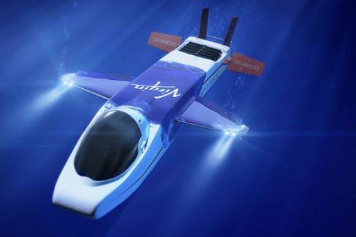
Deep Exploration Submariner Sir Richard Branson Unveils An All New Deep Exploration Submarine With Guinness World Record Aims. Most of us think of a war machine when we hear the word submarine. Since its inception, these 'underwater water ships' have mostly been used by countries to fire missile at others or to sink enemy ships with a deadly torpedo. But for sometime now, submarines have found a rather more 'creative' use. Today submarines are being used to fulfill man's wish to explore the undersea world. Of course, these submarines differ in a big way from the conventional military submarines. These are small submersibles designed to give the tourists a glimpse of the underwater world. The tourists can view the undersea world without getting wet through the transparent glass windows of these mini-submarines. This form of undersea tourism is gaining in popularity off-late. Many countries with long coastlines are adopting this form of tourism to boost their economy. This article will give you an idea about five submarines which are currently being used for undersea tourism as well as for scientific explorations around the world.
1. CQ-2 twin seater personal submarine.
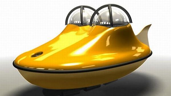
The C-Quester 2 or the CQ 2 submarine can carry two people up to a depth of 100 meters. But, the best thing about this submarine is that the cabin pressure of this submarine always stays at one atmospheric pressure which means that people traveling in this submarine will not have to worry about decompression while sailing in the ocean depths. The CQ 2 is a battery powered vehicle. On one full charge of its lithium-ion battery, this mini-sub can stay submerged underwater for two-and-half hours. But, on the downside, the battery takes 14 hours to fully charge. The CQ 2 has four 36V electric motors for propulsion underwater. A four-seater version of this submarine is also available.
2. Hammacher schlemmers submarine.
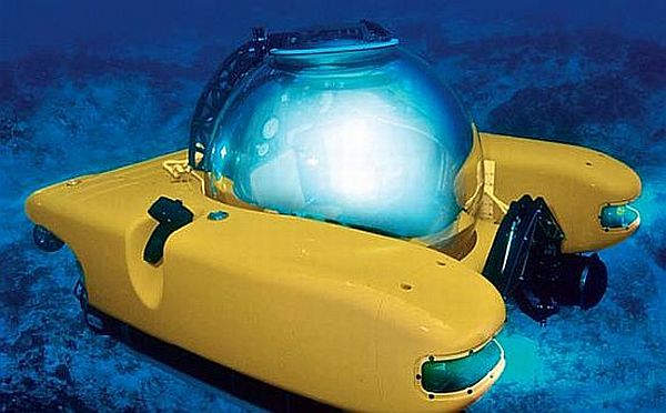
The Hammacher Schlemmers Personal sub is powered by two 3 HP thrusters. These thrusters provide the necessary power to the submarine to move around in every direction. The submarine has the capability to dive up to 1000 feet underwater and can stay there for 6 hours. The submarine, weighs in at 3000kg, is fitted with things like VHF radio, barometer, thermometer, fluxgate, depth gauges, hydrometer, GPS receiver, etc. A single Hammacher Schlemmers submarine will cost you $2 million.
3. personal submarines.
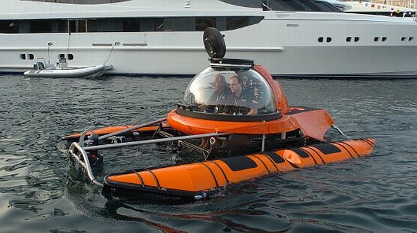
This is another personal submarine on offer from the Dutch submarine manufacturer. They have also designed the CQ submarines which have the capability to dive up to 100m beneath the waves. This particular model, named C-Explorers, has the capability to go up to 1000m underwater, carrying up to six persons on-board. Some of the technologies used in C-Explorer have been taken from CQ series of submarines. The C-Explorer has a catamaran style design with a fully acrylic transparent pressure hull for clear and unobstructed underwater viewing. The vehicle will be available in 1, 2, 4 & 5 models. The C-Explorer 1 will be powered by a 10 kWh lithium-ion battery while the other models will be fitted with a 40 kWh variant.
4. Raonhaje's EGO personal semi-submarine.
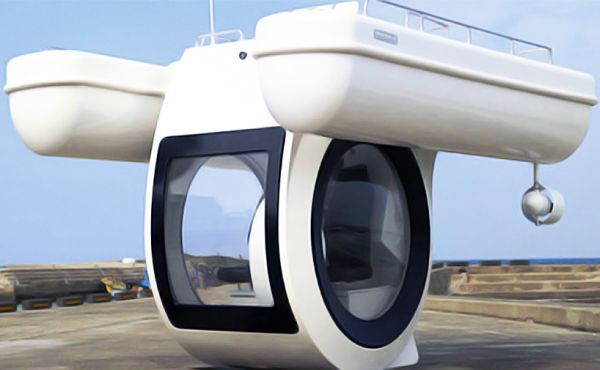
Korean company Raonhaje recently came up with this personal semi-submarine concept, the EGO. The EGO concept revolves around a circular container with two floating wings attached to the top of it. The wings have propellers fitted beneath them which propels this semi-submarine forward. The submarine is powered by 8-12 volts marine batteries and can carry up to three people. The battery of this submarine takes 6-10 hours to fully charge and gives the craft a top speed of 5 knots. The EGO has an endurance of 4 hours at top speed and 8 hours at a reduced speed.
5. SEAmagine's Smallest and Lightest Submersible.
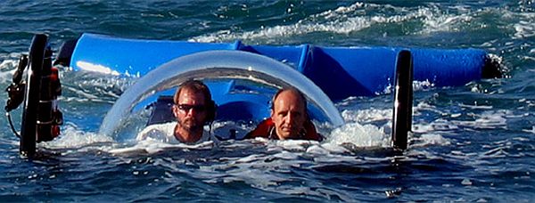
The Ocean Pearl mini-submarine from SEAamagine can carry two people up to a depth of 914 meters (3000 feet). The submarine has a bubble canopy that opens up like a clam shell to provide easy access to the passengers. The transparent bubble canopy also provides unhindered view of the ocean floor to the passengers. The submarine has been equipped with a high-tech full life support system which removes CO2 and supplies oxygen to the passengers.
Israel improving nuclear abilities.
The Guardian quotes report claiming Israel extending Jericho III missile's range, developing ICBM capabilities, expanding nuclear-tipped cruise missile enabled submarine fleet. Israel, the size of its nuclear-tipped cruise missile enabled submarine fleet is being increased and the country seems to be on course, on the back of its satellite launch rocket program, for future development of an inter-continental ballistic missile," the report said.
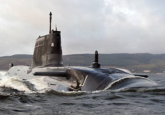
Nuclear submarine (Illustration: AP)
Israel currently has three submarines and two more being manufactured in Germany. Other countries, including Israel, India, China and Pakistan, are also expected to spend significant amounts of money on their strategic weaponry systems. The Basic report claimed that for countries such as Israel, Russia, Pakistan and France, having nuclear weapons is not just about deterrence. For Russia and Pakistan nuclear weapons are also designated for attacks, claimed the report.
Israel may lose German sub deal.
German Chancellor Angela Merkel's frustration over new east Jerusalem housing plans may jeopardize Israel's chances of getting new Dolphin class submarine. Top political sources said that Merkel was irked with Netanyahu, who "gave her the impression that he would be willing to suspend settlement expansion in order to push the Israeli-Palestinian peace talks." Israel's recent approval of 1,100 housing units in the Gilo neighborhood in Jerusalem led Merkel to announce that Netanyahu "cannot be taken seriously and has no intention of complying with the basic terms needed to renew the negotiations with the Palestinian." Merkel and Netanyahu shared strident words following the decisions, and relations between Jerusalem and Berlin have been strained since. Defense officials expressed concern over Berlin's intention to suspend and possibly cancel the submarine sale: According to foreign media reports, the new Dolphin was slated to join Israel strategic fleet. Earlier in 2011, Germany announced that it would grant Israel a €135 million aid package to build its sixth submarine. German funding has been a significant part in the creation of the Israeli Navy's submarine crops. The Navy currently has three Dolphin class submarines, and is expected to receive two new ones, currently under construction in Germany. According to foreign media sources, the new submarines will be equipped to carry nuclear warheads. The deal was originally approved by former German Chancellor Gerhard Schroeder, despite initial concerns that such ballistic capabilities may upset the nuclear balance in the region. Senior defense officials refused to comment directly, saying only that "The subject of the sixth submarine is currently being negotiation between the (Israeli and German) governments. It is inappropriate to hash the matter out in the media."
The Russian Northern Fleet Nuclear submarine accidents.
From 1961 up to the present, there have been a number of accidents and incidents involving Soviet/Russian nuclear submarines. At least 507 people have died in accidents on submarines throughout this period. The most serious accidents have been caused by fires that have resulted in the sinking of the submarine, or by severe damage to the nuclear reactor following overheating of the reactor core (loss of coolant accidents) and a number of smaller incidents in which radioactivity has been released. Most of the vessels affected by accidents have belonged to the Russian Northern Fleet. This chapter discusses only those accidents that have resulted in the loss of life and/or in releases of radioactivity. There have also been a number of other incidents in which Northern Fleet submarines have been involved. These include collisions with other submarines, fires at naval bases and shipyards, submarines that have become entangled in trawler nets, accidents during test launches of submarine launched missiles, collisions with icebergs and so forth.
Sunken nuclear submarines.
As a consequence of either accident or extensive damage, there are six nuclear submarines that now lie on the ocean floor: two American vessels (USS Thresher and USS Scorpion) and four Soviet (K-8, K-219, K-278 Komsomolets and K-27). The two American submarines and three of the Soviet nuclear submarines sank as a result of accident; the fourth Soviet vessel was scuttled in the Kara Sea upon the decision of responsible authorities when repair was deemed impossible and decommissioning too expensive. All four of the Soviet submarines belonged to the Northern Fleet. Despite the differences in time and in location, the Soviet submarine accidents all followed a similar pattern
-
Fire while submerged on return from patrol.
-
Surfacing of the submarine. Attempts made to salvage the submarine, both in submerged and surface position. By the time of surfacing, vessel had already lost power and possibility for outside contact.
-
Penetration of outside water into the vessel.
-
Command post loss of control over submarine's essential systems.
-
Loss of buoyancy and stability of pitch.
-
Capsize and sinking.
It was not always an accident involving the nuclear reactor that caused these submarines to sink. On all of the Soviet vessels that have sunk, the reactor's shut-down mechanism had been engaged. For extra security, the control rods were lowered manually to their lowest position, an operation entailing such great risk of radiation that it presented a real threat to life. There have been a number of incidents involving naval nuclear reactors of the Northern Fleet that have had serious consequences. Among them are accidents that have resulted in the deaths or overexposure to radiation of the crew, as well as extensive damage to the submarine. The damage was expensive and difficult to repair; and in some instances, the damage to the vessel was so comprehensive that future use was impossible. The three most serious accidents involving Soviet nuclear submarines are described below. The two American submarine wrecks are discussed in the Appendix.
K-8
The first accident involving a Soviet nuclear submarine involved the Project 627 A - November class vessel K-8, which sank in the Bay of Biscaya on April 8, 1970 while returning from the exercise OKEAN. Two fires started simultaneously in both the third (central) and eighth compartments. The submarine surfaced, but the crew was unable to extinguish the fires. The reactor emergency systems kicked in, leaving the submarine with virtually no power. The auxiliary diesel generators could not be started either. The control room and all the neighbouring compartments were filled with fumes from the fire. Air was pumped into the aft most main ballast tanks in an attempt to keep the vessel afloat. By April 10, the air tanks had been emptied, and water began to flow into the seventh and eighth compartments. On the evening of April 10, part of the crew was evacuated to an escorting ship. On the morning of April 11 at 06:20, the submarine sank at a depth of 4680 metres following a loss of stability in pitch. Fifty two people died, including the captain of the vessel. Details of this accident were kept secret until 1991.
K-219
In October 1986, the strategic nuclear submarine K-219 (Project 667 A - Yankee class) sank in the Atlantic ocean north of Bermuda with ballistic missiles on board after an explosion in one of the missile tubes. The explosion caused a leak in the fourth compartment (missile compartment). Steam and smoke from the missile fuel began to stream out of the damaged missile tube. At the time of the explosion, only one of the vessel's two reactors was running. The submarine surfaced and the other reactor was started up. Despite the fact that water was beginning to come in, a fire broke out in the fourth compartment. A short in the electrical system tripped off one of the submarine's emergency systems. One life was lost in the struggle to lower the control rods. Though still in a surfaced position, the buoyancy of the submarine was steadily impaired when water filled the main ballast tank. When the second reactor broke down, the crew was transferred to a rescue vessel. The captain and nine crew members remained in the conning tower, but when the bow began to sink, they were obliged to abandon ship. On October 6, at 11:03, the submarine sank with a loss of four lives. The reason for the explosion in the missile tube is unclear. There are two theories of how the accident happened: a defect in the missile tube itself or a fire that broke out following a collision with an American submarine The submarine had two nuclear reactors and carried 16 nuclear missiles]
K-278 (Komsomolets)
In April, 1989, the nuclear submarine K-278, Komsomolets, (Project 685 - Mike class) sank in the Norwegian Sea following a fire. Komsomolets was a unique titanium-hulled submarine that could dive to depths of 1000 metres. On the morning of April 7, 1989, the vessel was on the way back to her base at Zapadnaya Litsa, positioned at a depth of 160m approximately 180km south of Bear Island. At 11:03 the alarm sounded due to a fire in the seventh compartment. Eleven minutes after the fire had broken out, the vessel surfaced. However, the fire had caused short circuits in the electrical system which set off the reactor's emergency systems. The fire was so fierce that a leak was sprung in the compressed air system, and this led in turn to a spreading of the fire. Attempts by the crew to extinguish the flames were futile. The submarine lost power, and finally ran out of compressed air. By 17:00, the leak had worsened, and the submarine lost buoyancy and stability. The crew began to be evacuated into life rafts, but there were not enough rafts. The life rafts that were lowered were too far away for the crew to reach. At 17:08, the submarine sank at a depth of 1685 meters, with a loss of 41 lives and her commander. The ship Aleksandr Khlobystsov which came to the rescue after 81 minutes took aboard 25 survivors and 5 fatalities. The exact cause of the fire is unknown. One speculation is that the concentration of oxygen in the seventh compartment was too high, setting off short circuits in the electrical system. The nuclear submarine Komsomolets sank in the Norwegian Sea on April 7, 1989, south of Bear Island. The submarine sank with its reactor and two nuclear warheads on board, and lies at a depth of 1 685 metres. It has also been asserted that shortly before the accident, the vessel had completed a test that indicated it was not seaworthy. Others claim that K-278's crew was not qualified to serve on the Komsomolets
8.2 Reactor Accidents.
The most serious accident in which radioactivity is released is the meltdown of the reactor core on board the submarine. This is called a nuclear accident. There have been a number of both major and more minor incidents involving naval reactors. These accidents can be grouped into three categories according to the degree of severity:
-
Nuclear accidents;
-
Reactor accidents.
Nuclear accidents.
Nuclear accidents are classified either as "loss of control" (loss of regulation) accidents in which an uncontrolled chain reaction may occur, or as "loss of coolant accidents". There have been ten nuclear accidents in the entire period that Soviet nuclear submarines have been in operation, one of which occurred in 1970 during the construction of K-329, a vessel of the Charlie-I class. There were two incidents during refuelling operations on K-11 and K-431, another during repairs of a naval reactor at the shipyard (K-140), one during modifications of the submarine (K-222), four during operations at sea, and one during reactor shut down (K-314). Two of the accidents occurred on Pacific Fleet submarines, seven at the Northern Fleet, and one at the shipbuilding yard in Nizhny Novogorod
K-19
The first nuclear accident to occur on a Russian submarine was on the Northern Fleet's ballistic missile submarine K-19 (Project 658 - Hotel class). On July 4, 1961, during exercises in the North Atlantic, a leak developed in an inaccessible part of the submarine K-19's primary cooling circuit. The leak was specifically located to a pipe regulating the pressure within the primary cooling circuit. The leak caused a sudden drop in pressure, setting off the reactor emergency systems. To prevent overheating of the reactor, superfluous heat must be removed, and this is done by continually circulating coolant through the reactor. There was no built-in system for supplying coolant to the primary circuit, and it was feared that an uncontrolled chain reaction might start. An improvised system to supply coolant to the reactor was devised. This required officers and midshipmen to work for extended periods under radioactive conditions in the more remote areas of the reactor compartment as they attended to the leak in the primary circuit.[ The radiation in this case came from noxious gases and steam. All of the crew were exposed to substantial doses of radiation, and eight men died of acute radiation sickness after having undergone doses of 50 to 60 Sv (5000 - 6000 rem). The crew was evacuated to a diesel submarine, and K-19 was towed home to base on the Kola Peninsula
K-11
The second nuclear accident to occur was in February 1965 aboard the Project 627 - November class submarine K-11. The submarine lay in dock at the naval yard in Severodvinsk and work was underway to remove the reactor core (Operation No. 1). On February 6, the reactor lid was opened, and the following day, the lid was lifted without having first secured the control rods Releases of radioactive steam were detected with an abrupt deterioration of conditions. Radiation monitors were going off scale, and all personnel were withdrawn. No work was done on the submarine over the course of the next five days while the specialists tried to discover the reason for the problem. The wrong conclusions were drawn, and the raising of the reactor lid was attempted again on February 12. Once again, the control rods had not been secured, and when the reactor lid was raised, there were releases of steam and a fire broke out. There are no data on radioactive contamination levels or radiation exposure of the personnel. The reactor was finally retired and replaced
K-27
On May 24, 1968, the nuclear submarine K-27 (Project 645) was out at sea. During sea trials, the nuclear reactor had operated at reduced power, and on May 24, power inexplicably suddenly dropped. Attempts by the crew to restore power levels failed. Simultaneously, gamma radiation in the reactor compartment increased to 150 R/h. Radioactive gases were released to the reactor compartment from the safety buffer tank, and radiation on board the submarine increased. The reactor was shut down, and approximately 20% of the fuel assemblies were damaged. The incident was caused by problems in the cooling of the reactor coreThe entire submarine was scuttled in the Kara Sea in 1981
K-140
In August 1968, the Project 667 A - Yankee class nuclear submarine K-140 was in the naval yard at Severodvinsk for repairs. On August 27, an uncontrolled increase of the reactor's power occurred following work to upgrade the vessel. One of the reactors started up automatically when the control rods were raised to a higher position. Power increased to 18 times its normal amount, while pressure and temperature levels in the reactor increased to four times the normal amount. The automatic start-up of the reactor was caused by the incorrect installation of the control rod electrical cables and by operator error. Radiation levels aboard the vessel deteriorated
K-429
In 1970, while the brand new Project 670 - Charlie class submarine K-329 lay in harbour at the shipbuilding yard Krasnoe Sormovo in Nizhny Novgorod, there was an uncontrolled start up of the ship's reactor. This led to a fire and the release of radioactivity
K-222
On September 30, 1980, the submarine K-222 was at the factory in Severodvinsk due for a thorough reactor check. During the course of work, the submarine's crew left for lunch leaving the factory personnel on board the vessel. As a result of a breach in the pertinent procedural instructions, power was sent through the safety rod mechanisms without the controls also being engaged. Following a failure in the automatic equipment, there was an uncontrolled raising of the control rods with a subsequent uncontrolled start up of the reactor. As a result of this, the reactor core was damaged. This is one of the Pacific Fleet's Echo-I class nuclear submarines. This vessel suffered a leak of radioactivity following a fire while it lay off the coast of Japan on August 21, 1980. The crew on deck have put on protective clothing against the radioactive gasses from the reactor compartment. Nine crew members died in the fire and three others were injured.
K-123
On August 8, 1982, while on duty in the Barents Sea, there was a release of liquid metal coolant from the reactor of the Project 705 - Alfa class submarine K-123. The accident was caused by a leak in the steam generator. Approximately two tons of metal alloy leaked into the reactor compartment, irreparably damaging the reactor such that it had to be replaced.[590] It took nine years to repair the submarine.
K-314
On August 10, 1985, the Project 671 - Victor-I class submarine K-314 was at the Chazhma Bay naval yard outside Vladivostok. The reactor went critical during refuelling operations because the control rods had been incorrectly removed when the reactor lid was raised. The ensuing explosion led to the release of large amounts of radioactivity, contaminating an area of 6km in length on the Shotovo Peninsula and the sea outside the naval yard. Ten people working on the refuelling of the vessel died in the accident. The damaged reactor compartment still contains its nuclear fuel.
K-431
In December 1985, the reactor of the nuclear submarine K-431 (Project 675 - Echo-II class) overheated while the vessel was returning to base outside Vladivostok. It is now laid up at the naval base in Pavlovsk.
K-192 (formerly K-131)
On June 25, 1989, while on the way back to its base at Gadzhievo on the Kola Peninsula, the Project 675 - Echo-II class class submarine K-192 suffered an accident involving one of the two reactors on board. At the time of the accident, the submarine was in the Norwegian Sea, about 100 km north-west of Senja in Troms and approximately 350 km south of Bear Island. A leak was discovered in the primary circuit, and the submarine surfaced immediately. Because of the leak, the levels of coolant in the primary circuit had dropped, and the crew hooked up water from the submarine's fresh water tanks. The reactor was not immediately shut down. The contaminated water from the leak was pumped out into the sea, but there is no information about its activity level. When the vessel's fresh water supplies had been consumed, a hose was connected from the Soviet freighter Konstantin Yuon to maintain a supply of coolant to the reactor. Afterwards, the reactor was shut down, and the submarine ran on its diesel engines around the Finnmark coast towards the Kola Peninsula. The temperature of the coolant was at 150°C on the morning of June 26, 120°C the same evening, and 108°C on June 27. Releases of radioactive iodine were detected in the areas immediately surrounding the submarine, and sometime later, also at a monitoring post at Vardø in Finnmark.[596] The Northern Fleet service ship Amur also came to the assistance of K-192, and the radioactive contaminated coolant was transferred to Amur which had a treatment facility on board for liquid radioactive waste. On June 26, the crew of K-192 made an attempt to close the leak in the pipe from the cooling system, and in order to accomplish this, the supply of coolant from Amur was shut off. It is not known how long the coolant supply was shut off; however, the individual in charge of monitoring the coolant supply "forgot" to turn it on again when he left his post to go and eat dinner. This person later claimed that he had not in fact forgotten, but was waiting for orders to turn on the supply again. These orders did not come before dinner. Due to the loss of coolant, the temperature in the reactor increased and the alarm went. The supply of coolant was immediately switched on again, but too late. The supply of cold coolant led to the cracking of the overheated fuel assemblies, and water came into contact with the uranium fuel. The heavily contaminated water being pumped over to Amur led to the breakdown of the treatment plant. Subsequently, water was taken in directly from the sea and pumped out into it again. The total activity and amounts of contaminated water released from K-192 into the sea is not known. At this point, the vessel was positioned in international waters somewhere between the North Cape and the Kola Coast, more than 12 nautical miles off the coast. On June 28, K-192 arrived at the Ara Bay base facility belonging to the naval base at Gadzhievo.[598] At base the activity of the contaminated coolant was estimated at 0.3 Ci/l, totalling 74 TBq, 2 000 Ci.[599] The submarine's crew received doses of up to 40 mSv (4 rem). K-192 was laid up at the base facility in the Ara Bay until 1994 when it was towed to Navy yard No. 10 - Shkval. Compressed air is now pumped into the hull to maintain buoyancy. The fuel assemblies in the damaged reactor cannot be removed by standard procedures
K-8
On October 13, 1960, one of the most serious accidents involving a naval reactor occurred on a Northern Fleet vessel. The incident was caused by a loss of coolant to the reactor, and is classified accordingly. The Project 627 - November class submarine K-8 was on exercise in the Barents Sea when a leak developed in the steam generators and in a pipe leading to the compensator reception. The equipment for blocking these leaks was also damaged such that the crew itself began the work of stopping the leak. They mounted a provisional system for supplying water to the reactor to ensure cooling of the reactor and thereby avoid the risk of a core melt in the reactor. Large amounts of radioactive gases leaked out which contaminated the entire vessel. The true activity of the gases could not be determined because the instrumentation only went to a certain level. Three of the crew suffered visible radiation injuries, and according to radiological experts in Moscow, certain crew members had been exposed to doses of up to 1.8 - 2 Sv (180 - 200 rem.
Some SSN nuclear power units failure and accidents causing radiation discharge.
SSN |
Time |
Incident |
K-386 |
1976 |
Main condenser breakage (2 persons injured to death) |
1986/87 |
Cleaning unit leakage |
|
1984 |
Leaky steam generator |
|
1985 |
Leaky steam generator |
|
1984 |
Leaky steam generator |
|
1985 |
Leaky steam generator |
|
1984 |
Leaky steam generator |
|
1984 |
Leaky steam generator |
|
1987 |
Leaky steam generator |
|
1984/86 |
Critical underspace leakage of primary circuit |
|
1984/86 |
Critical underspace leakage of primary circuit |
|
K-37 |
1984/86 |
Critical underspace leakage of primary circuit |
1986 |
Critical underspace leakage of primary circuit |
|
1985 |
Automatic control break |
Fires on Submarines resulting in loss of life.
In addition to the accidents involving fires whereby the vessels themselves were lost, there have been four serious accidents involving fires on Northern Fleet nuclear submarines that have resulted in the loss of human life.
K-3
On September 8, 1967, while sailing in the Norwegian Sea on the way home to its base on the Kola Peninsula, a fire broke out on board the nuclear submarine K-3 (Project 627 A - November class). The fire started in the submarine's hydraulic system, and crew members in the compartment when the fire broke out had to evacuate the compartment. This resulted in the flames spreading to other parts of the submarine. The automatic extinguishers were based on CO2 gas, and this gas killed the crew members who were in the first and second compartments foremost in the submarine. When the dividing door in the bulkhead from the third compartment was opened to see what had happened to the people in the second compartment, the gas spread, and more people lost consciousness. The foremost compartments were then completely sealed off, and the submarine surfaced. Four days later, K-3 had returned to base. A total of 39 crew members died in the fire .
K-19
On February 24, 1972, while the vessel was on patrol in the North Atlantic, a fire broke out in the ninth compartment on board the Project 658 - Hotel class submarine K-19. The fire started at 10:23 AM, and the ninth compartment was immediately closed off to prevent the fire from spreading to other parts of the vessel. Twelve crew members in the tenth compartment aft in the submarine were thereby isolated, and were not rescued until March 18, after 24 days of fighting the fire. A total of 28 people died in the fire which was caused by a break in one of the hydraulic pipes. Over 30 ships were involved in the rescue of K-19, and the submarine finally returned to base on the Kola Peninsula on April 4.
K-47
On the 26 of September 1976 when the submarine K-47 was in the Barents Sea on its way to the home port fire broke up in the 8-th compartment. 8 crew members died of injuries.
K-131
On June 18, 1984, a fire broke out in the eighth compartment aboard the Project 675 - Echo-II class submarine K-131. This submarine too was returning to base on the Kola Peninsula. The cause of the accident was that the clothes of one of the crew members caught fire while he was working on some electrical equipment. The fire spread to the seventh compartment and caused the death of 13 crew members.
Some Emergencies on SSNs.
SSN |
Time |
Incident |
Apr. 1984 |
Fire |
|
March 1985 |
Fire |
|
Dec. 1986 |
Fire caused by shot circuitry in electrical equipment |
|
March 1985 |
Fire caused by shot circuitry in electrical equipment |
|
K-369 |
Dec. 1985 |
Fire |
Dec. 1987 |
Fire |
|
Apr. 1984 |
Fire |
|
May 1984 |
Fire |
|
1985 |
Oil heater explosion |
|
1985 |
Fire |
|
Jan. 1984 |
Water penetration into the reactor compartment |
|
K-475 |
1984 |
Water penetration into the reactor compartment |
Causes of Submarine Accidents.
The complex "man-machine" system represented in the modern nuclear submarine, increases the risk of accidents. The causes of the various accidents depend to a large extent on both the qualities of the reactor and the situation leading up to the accident. The existing framework of project development, building and delivery of military technology (navy) and ammunition is not regulated by law, but by decree of defunct authorities, such as the Central Committee of the Communist Party, various councils of Soviet ministers, the military-industrial complex, as well as joint decisions handed down by the Ministry of Ship Building and the Ministry of the Navy. The administrative body of the military industrial complex, led by the vice-chairman of the council of ministers, itself issued the documents that established the norms, and it was this same body that monitored and enforced the norms that it had itself created. The practice of merging the functions of public agencies contributed to the fact that the Navy itself did not take part in working out quality control and safety requirements for nuclear submarines. Even if the Navy politely refused to receive equipment that they knew in advance to be defective, it could nonetheless be forced to accept it through a common resolution issued by the authorities. This structure of resolutions and decrees has followed the delivery of all new nuclear submarines to the Soviet Navy. Soviet nuclear submarines were built under enormous time constraints. If the Central Committee of the Communist Party had determined that a particular submarine was to be built by the close of a certain year or a particular season, the submarine yards could not postpone delivery, even if the vessel had not been completed or undergone sea trials. Hence nuclear submarines were often delivered to the Navy without all the necessary safety equipment having been installed. Furthermore, the procedural guidelines and the specifications of the contract were modified and simplified. It was not uncommon for a nuclear submarine to be delivered to the Navy from the building yard with missing or defective parts. In 1989 there were 529 complaints of nuclear submarines being delivered with faulty equipment. In 1990-91 a new nuclear submarine was returned to the building yard due to numerous defects in the mechanical equipment. Another submarine was delivered without light switches having been installed in the cabins or in the missile compartment. The servicing and repair of nuclear submarines was carried out at naval yards that fell under the jurisdiction of different authorities. This system was established at the dawning of the age of nuclear submarines and it came to the full during the cold war. Almost 25 nuclear submarine projects were initiated and developed during this period. The lack of sufficient standardisation led to problems in the planning stage, in the competence levels of the crew and in an unavailability of spare parts. The quality and safety of the equipment was compromised, and this has been one of the most important contributing factors to the higher incidence of accidents amongst Soviet nuclear submarines as compared to for example American vessels. There were also many common factors in the accidents on board Russian nuclear submarines, reflected again and again in the accident statistics:
-
The frequency of accidents was increased as early as the planning stage due to technological deficiencies in a number of areas (information, securing secrets of propulsion and means of carrying out research) and deficiencies in construction. One of the main problems was the poor quality of the metals and materials that were used.
-
At the construction stage, breaches in the technological standards by the builders affected the quality of the finished product such that the finished submarines that were actually delivered to the Navy fell short of the quality of their design.. Furthermore, the schedule for delivery of various systems and parts, as well as the order in which operations were completed and breaches in the proper technical procedures, all contributed to lowering the quality of the submarine. The quality of the work was poor due to a lack of technical understanding amongst the workers. In some instances, there was not even enough technical equipment at the navy shipyards and floating bases.
-
During the testing and approval stage, there were interruptions to the schedule due to delays in deliveries and installation of parts and systems. Under outside pressure from concerned parties, the submarines were approved even before the equipment on board had been tested.
-
The frequency of accidents also increased during the submarines' operational life due to poor maintenance, a disregard of the directions for use and improper procedures for technical equipment and ammunition. The crew were assigned to tasks other than their direct responsibilities, and therefore were lacking in training, especially with regards to measures designed to ensure the survivability of the submarine. At one time, one submarine commander sent in a complaint that eleven of the 28 new members of the crew could not speak Russian and therefore were not qualified to work with the nuclear reactor. Many of the new crew for the nuclear submarines had received only six months training, training that often was insufficient or irrelevant to the situations they might confront on a nuclear submarine.[608] There was a widespread irresponsible attitude from incompetent outside specialists. The crews were too inexperienced to be able to foresee potential dangers that could lead to critical situations while the submarine was in operation. The search and rescue bases, which have shown a lack of co-ordination in conducting searches, weakened overall preparedness in a number of accidents. The absence of formal conclusions at inquests and a lack of ready information in response to the questions about the nature of the accidents and their frequency resulted in a failure to implement measures to improve the conditions on board the nuclear submarines.
A number of general measures could be implemented to reduce the frequency of accidents, including the following:
-
Transition and transformation into a professional navy.
-
Reform of the governing powers in the military industrial complex; division into legislative, executive and administrative functions.
-
Development, production and delivery of ships and military technology regulated by law.
Without implementing these types of reforms, it will be difficult to reduce the frequency of accidents.
There are three main factors contributing to the safe operation and use of nuclear submarines:
-
The quality of the design and construction of the vessel, its ammunition and technical equipment;
-
Skill in the operation of nuclear submarines and in the use of pertinent technology over the course of the vessel's operational lifetime;
-
Professional training of the crew and professional administration of work on nuclear submarines.
Russia continues to lead the world in the field of submerged speed and deep-diving submarines. The shipbuilding industry in the former Soviet Union expended considerable resources and employed experienced and highly skilled personnel to build its submarines. This made it possible to build submarines at a rapid pace; however, there were hardly any vessels, submarines or surface vessels, that were delivered to the Navy free of flaws. The deficiencies were often serious. As a rule, nuclear submarines were delivered from the shipbuilding yards at the end of the year. Regardless of the circumstances, the shipbuilding yard had to guarantee that the vessel would be delivered no later than December 31. Tremendous pressure was put on the chairman of the State Committee for Approval from the whole hierarchy of the Ministry of Shipping and Industry, and strange though it may seem, he was also pressured by the Chief Commander of the Navy. The chairman faced a choice between telling the truth about the condition of the submarines - and thereby lose his job - or else avoiding the question. The latter course of action was invariably chosen. Regardless of incompletion or missing parts, nuclear submarines were delivered to the Navy as long as they were capable of operating under their own steam. Every so often, a submarine might remain at the building yard until it was capable of operating independently. A special contract was established entitled Joint Decisions of the Ministry of Shipping and the Navy, where the building yards promised to improve or amend faults and deficiencies within a certain period of time. The Navy also agreed to this. Any submarine that formally entered service with the Navy could be assigned to any kind of assignment or mission within the Navy's sphere of operation, including battle. However, there was no sense of concern or organised plan for conditions of storm or chaos; nor were there any preparations made for such emergencies. It was precisely here that accidents could happen. A serious consequence of this lack of concern was its unfortunate effect on the attitude of the crew - rather than feeling a sense of responsibility themselves, they simply signed on for duty on incomplete nuclear submarines and hoped for the best.
The day-to-day running of a nuclear submarine involves a whole series of routine procedures and operations, ranging from weekly monitoring and overhaul to varying and more extensive service procedures at the shipyard. The execution of such work requires a sufficient number of naval yards and repair shops, as well as spare parts and operative materiel. The bulk of the Northern Fleet's resources was allocated to the development and construction of its main components: ships and ammunition. The rest received what was left - but this was very little. By the end of the 1980s, the Soviet Union had more nuclear and diesel submarines than all the other nations of the world combined. Yet Russia's submarines barely achieved half of the American operational life. The useful life of the Russian submarine was shortened by the limited possibilities for repair and an underdeveloped industry. The division of labour aboard the nuclear submarines could also have been better. Today, the vessel's commanding officer has total responsibility. He is also liable for mistakes made by his subordinates, even when it is apparent that another individual's poor judgement has caused the error. The problem is that the commanding officer seldom has the opportunity to discharge this responsibility. Furthermore, the crew of submarines, especially officers, work under conditions of constant physical and psychological overload, with irregular working hours and rest periods.
Japanese Midget Submarine found.
The remains of a Japanese mini-submarine that participated in the Dec. 7, 1941, attack on Pearl Harbor have been discovered, researchers are to report today, offering strong evidence that the sub fired its torpedoes at Battleship Row.
Five mini-subs were to participate in the strike, but four were scuttled, destroyed or run aground without being a factor in the attack. The fate of the fifth has remained a mystery. But a variety of new evidence suggests that the fifth fired its two 800-pound torpedoes, most likely at the battleships West Virginia and Oklahoma, capsizing the latter. A day later, researchers think, the mini-sub's crew scuttled it in nearby West Loch. The loch was also the site of a 1944 disaster in which six tank landing ships preparing for the secret invasion of Saipan were destroyed in an ammunition explosion that killed 200 sailors and wounded hundreds more. When the Navy scooped up the remains of the so-called LSTs and dumped them outside the harbor to protect the secrecy of the invasion, it apparently also dumped the mini-sub's remains, which were mingled with the damaged U.S. ships. The two-man, 80-foot-long sub in question [of the Ko-hyoteki class] does not have a name of its own. Each of the five subs in the attack was carried by a conventional submarine and took its name from the mother boat. It is thus called the I-16-tou -- tou being Japanese for boat. Powered by a 600-horsepower electric motor, the sub could reach underwater speeds of 19 knots, twice as fast as many of the U.S. subs of the day. The Japanese navy modified net cutters on the subs for specific missions, and the one on the wreck was identical to those on the other mini-subs. No torpedoes were found on the wreck, and evidence suggests that they were not present when the boat was sunk. A newly declassified photograph taken by a Japanese plane during the attack appeared to show a mini-sub firing a torpedo into Battleship Row. A report to Congress in 1942 by Adm. Chester W. Nimitz describes an unexploded 800-pound torpedo recovered after the battle. That's twice the size carried by the torpedo bombers. That torpedo was apparently a dud that missed the West Virginia. But an examination of the remains of the Oklahoma shows that it apparently had underwater damage much larger than that associated with aerial torpedoes. An underwater blast would have caused it to capsize, Stephenson said. "Otherwise it would have settled to the bottom upright," like the other sunken ships. Five of the Ko-hyoteki midget submarines were used to attack Pearl Harbor. Some were captured in wrecked condition shortly after the attack, like this one, washed up on the beach at Oahu.
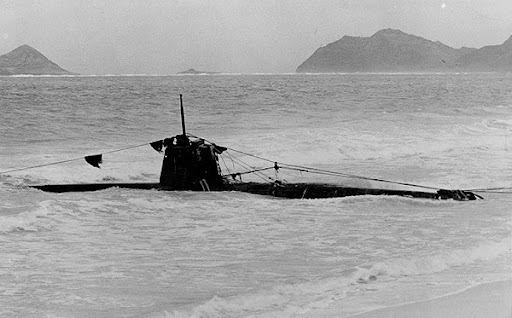
One midget submarine was claimed as sunk by the destroyer USS Ward on the morning of the Pearl Harbor attack. Long dismissed, her claim was ultimately verified by the discovery of the wreck of the submarine she attacked, with shell holes precisely where the Ward claimed to have hit her. The photograph below shows the Ward's victim on the seabed.

The Ko-hyoteki class midget submarines were also used to attack the harbor in Sydney, Australia, in 1942. Several Ko-hyoteki class midget submarines are on display. One is in the National Museum of the Pacific War in Fredericksburg, TX; another may be seen at the US Navy Submarine Force Museum in Groton, CT; and one is mounted ashore on the Pacific island of Guam (shown below).
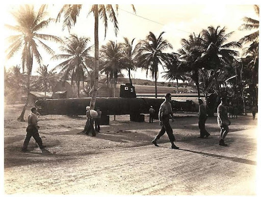
HUNT FOR THE SAMURAI SUBS.
Just before the atomic bomb forced Japan into submission, the Imperial Navy sent a fleet of incredibly advanced combat subs to attack a major U.S. naval base in the Pacific. But when Japan surrendered, the U.S. Navy confiscated them, only to later have them scuttled near Hawaii when Soviet scientists demanded access. The war machines’ precise location would remain a mystery for decades. Now a team of explorers thinks they can find some of these lost subs in the Pacific’s dark waters. From the Hawaiian island of Oahu, deep submergence vehicle pilots Terry Kerby and Max Cremer, along with a team of devoted explorers, prepare to dive to depths of nearly 3,000 feet to hunt for some of WWII’s largest and fastest submarines — in a Japanese super-submarine graveyard ? and solve one of the war’s great mysteries. The I-400 class Japanese submarines built during WWII were the largest submarines ever built, at 400 feet long (or longer than a football field), until the introduction of nuclear-powered submarines in the 1950s and ‘60s.
-
With a range of 37,500 miles at 14 knots, the I-400 class submarines were able to go one and a half times around the globe without refueling, a capability that has never been matched by any other diesel-electric submarine.
-
Special aircraft-carrying submarines with powerful torpedoes were built to attack the U.S. mainland. Their target later changed to the Panama Canal, but they never carried out either mission.
-
At the end of WWII, the U.S. Navy captured the subs and sailed five of them for evaluation: three aircraft-carrying submarines (I-400, I-401, I-14) and two fast attack subs (I-201, I-203).
-
The United States was the only country that performed inspections on this technology. When the Soviet Union demanded access in 1946, the U.S. Navy scuttled the subs off the coast of Oahu.
-
Japan’s aircraft-carrying submarines carried up to three bombers, which could be launched off the deck of the submarine by catapult ? some in as few as seven minutes.
-
The Aichi M6A1 Seiran plane built for the subs could carry one aerial torpedo or a bomb weighing nearly 1,800 pounds, along with a crew of two — a pilot and an observer.
-
Japanese subs used the powerful Type 95 torpedo, which utilized pure oxygen to burn kerosene, giving it three times the range of the Allies’ torpedoes. They were also harder to detect and avoid because of their reduced wake.
-
The I-400 sub had radar so it could detect the enemy. Its exterior had a sonar-absorbing coating, making it less detectible.
-
Crew aboard the aircraft-carrying submarine were limited to drinking half a cup of liquid with every meal, and were prohibited from taking showers or washing their clothes. There was only one toilet aboard, and waste tanks were often not emptied for fear of the enemy detecting them.
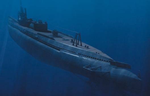
Wide shot of the Sen-Toku class “special attack” sub emphasizing the stern section (computer generated image).
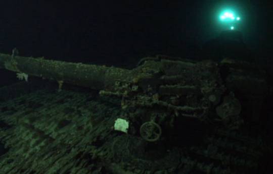
A deck gun located on the I-401 submarine wreck, with the Hawaii Undersea Research Lab’s Pisces submersible in the background.
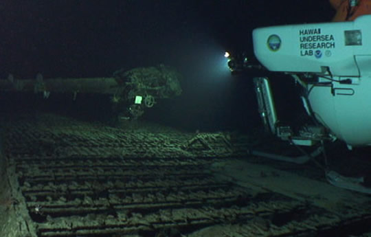
At the scene of a I-14 underwater submarine wreck, the Pisces looking at the deck gun of I-14. The I-14 is one of 5 Japanese submarines sunk by the US Navy in 1946.
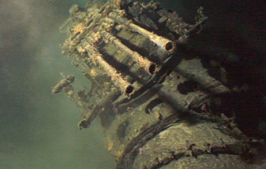
A close up shot of triple deck gun at the scene of the I-401 underwater submarine wreck. The I-401 is one of 5 Japanese submarines sunk by the US Navy in 1946.
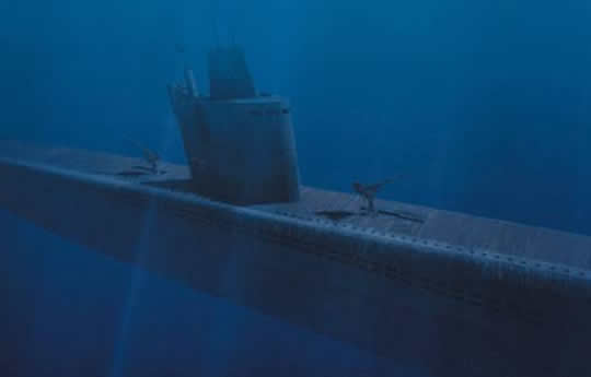
The conning tower and machine gun on a Sen-Taka class “fast attack” submarine (computer generated image).
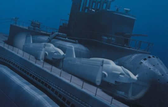
Hanger with two Seiran planes on a AM-Class submarine (computer generated image).
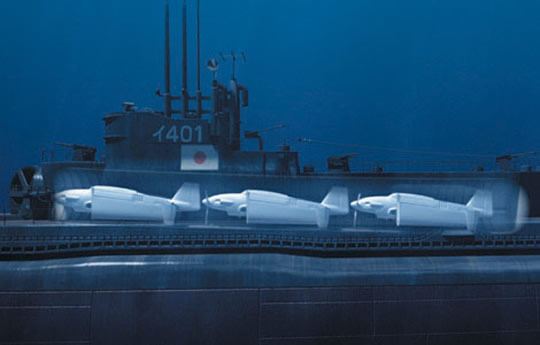
Three Seirans sitting inside the hanger of a Sen-Toku class “special attack” submarine (computer generated image).
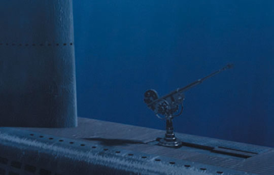
Machine gun on the deck of Sen-Taka class “fast attack” submarine (computer generated image).
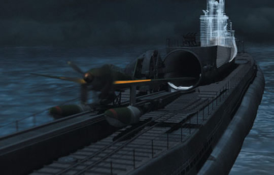
Seiran plane being catapulted from the deck of a Sen-Toku class “special attack” submarine (computer generated image).
U-BOATS FOR SALE.
These U-boats are ex military diesel-electric submarines, 300 feet (90m)
long. Designed for continental shelf operations, with a range of two thousand
miles. These submarines are not always in working order, and may have
been partially stripped of some internal parts. Ideal for conversion to
use as maritime museums, cocktail bars or restaurants in static locations.
Crew: 75. Displacement: 2,475 tons.
Russian Foxtrot diesel-electric submarine in working order. US$11 million.
Swordfish diesel-electric submarine in working order. Two available. US$POA
NEW **** RUSSIAN SUBMERSIBLES FOR IMMEDIATE SALE ****
As always we have a wide range of submarines (big and small), plus workclass and eyeball Rovs for sale. Priced to suit all budgets and tasks. Silvercrest Submarines can arrange submarine and Rov maintenance programmes, and Pilot Training courses for purchasers. Submarine certification and refit programmes can also be provided. Further information available on request.
Please contact us at anytime to discuss your underwater vehicle requirements. We are always happy to exchange ideas and offer advice.
Submersible, ROV and Subsea Motors.
Submersible Motor Engineering/Silvercrest offer complete submersible electric motor rewinds, submersible motor rebuilding, electrical conversion and construction modification. Submersible Motor Engineering/Silvercrest can repair and completely rebuild the following listed motors. Alstra, Aturia, Bamsa, B. J., Elmaksan, Exodyne/EEMI, G.E., Mercury, Oddesse, Pleuger, Saer, S.M.E., Subteck, Sumo, Sun Star, U.S.
Submersible Motor Engineering/Silvercrest Repair and rewind of large high voltage (500kW 6600V) submersible electric motors.
SUBMERSIBLE MOTOR ENGINEERING/SILVERCREST offer High Temperature Submersible motors in 6"to 20" frames suitable for operation in ambient of 75 Deg.C. High Voltage water filled submersible motors (300V, 4160V and 6600V). Upgraded Temperature Monitoring unit available with new improved user-friendly parameter setting.
SUBMERSIBLE MOTOR ENGINEERING ROV motors suitable for depths of 4000M.
SUBMERSIBLE MOTOR ENGINEERING/ SILVERCREST, design, manufacture, and supply, submersible electric motors for deep well submersible pumps, SUBSEA and ROV electric motors for SUBSEA equipment, submersible electric motors for sump pumps, and any special purpose submersible electric motor requirements.
SUBMERSIBLE MOTOR ENGINEERING/SILVERCREST also offer complete motor repair and rewind of all name brands of submersible motors, both water and oil filled.
Reliability applications to submersible turbine pumps and associated equipment.
Over the last quarter century there has been exponential growth in the Equipment Condition Monitoring Industry due to the benefits in costs savings when applied to industry. The following is an overview of how this same technology can be applied to submersible pump applications.
Unforeseen equipment failures are impacting facility performance standards.
Equipment run times are below expectations.
Excessive wear is requiring extensive repairs
Secondary damage such as motor repairs due to running with excessive pump wear.
The current reliability program does not meet corporate or agency mandates.
Facility managers have a feeling of “running blind” in that they can only hope that spare equipment does not fail while repairs are made to primary units.
All of the above can be managed effectively with the current technology at hand when applied in a coherent manner. Determining equipment condition and providing analysis to the end user is a fairly strait forward process. The return on investment (ROI) is dependent on the customer’s ability to assimilate the information and apply it effectively. It is then the challenge and task of the consultant to understand that potential and monitor the program to insure the best overall value is realized. Thus in going forward, in any program there must first be goals and benefits to be expected, then a means to quantify. With respect to submersible pump applications, a combination of monitoring the motor and pump is critical. The addition of frequency based vibration analysis and pump performance trending along with utilizing existing motor temperature data (RTD transmitters), provides a powerful tool in allowing facility managers to make decisions based on equipment condition. Equipment maintenance then can be managed on a condition based program as opposed to the customary reaction based “fix it when it fails” approach. Many times the pump performance is adequate enough to meet surface flow requirements even while the unit is in advanced stages of mechanical failure. When this situation goes unnoticed, excessive pump repairs and unnecessary motor damage occurs. By adding vibration analysis and pump performance trending, mechanical integrity can be established, monitored thus enhancing the ability to manage operations and maintenance. The role of the Reliability Consultant is to understand the anatomy of the equipment in use, the correct application of technology available and where the potential value is for the customer.
In our experience with monitoring rotating equipment there are three fundamental benefits in which one or two may apply to any given process. To relate this to submersible pump applications:
Pump and motor mechanical integrity
Pump water to wire efficiency
Secondary damage requiring extensive repairs
The ability to monitor key performance indicators (KPI) enables the analyst to identify changes in pump efficiency and mechanical health.
Typical Key Performance Indicators monitored are:
Amperage (3 legs)
Voltage (3 legs)
Actual RPM
Thrust bearing temperature
Winding temperatures
Top end bearing temperature
Vibration (frequency based spectrums analysis)
Water to Wire efficiency (KW vs GPM)
Pump design vs pump performance
Fluid level, flow, discharge pressure.
The availability of acceleration data from the submersible vibration sensor provides verification of defects indicated from surface monitors as well as mechanical defects that would be undetectable otherwise. By monitoring these KPI in concert and trending values the following can be detected and typically identified with relative confidence.
CAVITATION.
Excessive bearing clearances within pump and motor
Pump impeller damage or imbalance
Pump to motor coupling defects
Motor rotor bar defects
Motor winding defects
Inadequate cooling across the motor
Changes in well bore entry (fluid levels)
Surface drive unbalance
Holes or leaks in column pipe (tubing)
Plugged or restricted pump suction issues
When a progressive decline in pump performance or a mechanical defect is identified, it can be trended for increases and maintenance scheduled prior to failure based on condition and where it is in the normal life cycle. An example of the value in this is where there may be 8 pumps in service, and 6 must be online at any given time to meet minimum requirements. In the course of monitoring it is established that one unit is in advanced stages of wear, and two other units are in moderate stages:
Removing the unit in advanced stages and repairing while reasonable life is expected for the remaining 7 units provides knowledge that meeting a minimum of 6 units online can be expected and repairs are reasonably minor limited to a worn pump. In contrast, most maintenance programs would allow the more advanced unit to run until failure, in which case the other two moderate units now have advanced to later stages of life unbeknown to operations. A scenario now arises that one unit is down for extensive repairs such as motor and pump, and two of the remaining 7 units are in a high probability of failure thus exposing the operation to less than the minimum of 6 units in service. Another example of condition-based maintenance is seasonal considerations that provide unique advantages to maintenance on a scheduled basis.
Infant mortality issues can be identified when units are first installed, prior to demobilizing pulling equipment. This can provide significant savings.
When monitoring water to wire efficiency, and comparing expected annual operating expense of new equipment vs. existing, pump replacement can be made based on annual economical expense considerations. A considerable savings in energy costs can be realized with the added benefit of increased reliability in having new equipment in service.
SUBMERSIBLE MOTOR ENGINEERING Heat Exchanger Motors.
Submersible Motor Engineering now offer a complete range of water filled, water tight, submersible motors with integral heat exchangers in the 10",12",14" and 16" for 2 pole and 4 pole speeds.
These motors offer a significantly lower temperature rise when compared with standard submersible motors. This is an advantage that can be utilized when customers want to operate in water with a high ambient temperature or when there will be minimal cooling water flow.
Even with the standard applications the lower temperature rise will extend the life of the motor significantly. There is an accepted rule of thumb for electrical insulation that its life is shortened by one half for every 10°C increase in operating temperature. The winding operating temperature for a normal water filled submersible motor is about 70 Deg. C in 25 Deg. C. water, while a SUBMERSIBLE MOTOR ENGINEERING Heat Exchanger Motor will be running at about 45 Deg. C. - this is 25 Dec. C. cooler. This magnitude of difference in temperature rise will have a significant positive impact on motor life.
The basic design principle for these motors is to circulate the internal water in the motor to remove the heat from the "active" parts of the motor and then pass it through a heat exchanger which brings the internal water back to somewhere close to the external ambient water temperature - before feeding it back through the "active" parts again to remove more heat. The heat exchanger increases the external surface area of the motor by 50% and the water circulation allows the heat to dissipate more evenly and quickly out of the motor and into the external water. The small impeller inside the motor that circulates the water has an insignificant impact on the motor efficiency in terms of additional load, while the motor has an improved efficiency because the stator and rotor copper losses are reduced due to the lower operating temperature.
GENERAL INFORMATION ON SUBMERSIBLE ELECTRIC MOTORS.
Submersible electric motors are generally long and thin and designed to operate in a borehole coupled to a submersible multistage pump. In recent years the motors have been used in a number of different applications.
Typical applications are:
Submersible pumps for water supply - drinking water and industrial water. Booster pumps for high-rise buildings. Mine dewatering. Dewatering for Civil Engineering Projects. Irrigation. Fire fighting and sprinkler systems. Air conditioning systems. Offshore oil rigs - for pumping of seawater as ballast, and as fire pumps. Water treatment plants. Fountains.
These motors, with multistage pumps attached, are designed to be lowered into a small diameter borehole to pump ground water. Typical bore holes have 4",6",8",10",12" and 14" internal diameters usually this is a steel or plastic pipe which is pushed into a hole after it is drilled to form the well liner or well casing.
The motors are actually smaller than their dimensional name implies. The Inch dimension actually refers to the ID of the hole not the motor diameter. The motors need to be smaller than the hole to allow water to pass between the motor and the well liner and into the pump.
There are two different types of submersible motor:
Water filled Type, and ![]()
![]()
![]() Oil filled Type.
Oil filled Type.
Note: Oil filled motors can be filled with a Vegetable oil which is safe for human consumption, however most water Authorities do not want to take the risk of consumers complaining of oil in their water, which could happen, if and when, the oil leaks from the motor.
Costs vs Reliability.
Canned type motors are slightly more expensive than oil filled or water filled motors. Oil filled motors in the smaller sizes are less expensive than water filled motors. Canned and water filled motors tend to be more reliable than the oil filled motors, because of the difficulty of ensuring that the oil can expand and contract without escaping from the motor.
Cooling and Good Water Flow
These motors rely on good water flow past the motor. Water flow velocity must be between 0.5 ft/sec. to 10 ft/sec. (15cm/sec to 300 cm/sec). If the flow is less than this the motors will probably overheat and burn out. Surprisingly if the flow is more than this, motors will also overheat and burn out because the high velocity does not allow efficient heat transfer from the motor to the water. These motors are designed for high power outputs in small sizes in comparison with normal air-cooled motors. Because water is a very efficient cooling medium, compared with air, the current density in the stator winding is much higher than an air-cooled motor. This is acceptable provided the external body of the motor is efficiently cooled be the external water. If there is no external water flow or if the external water ambient temperature is too high the motor will overheat. If the internal water reaches boiling point it will form steam that will force its way out of the motor past the seals. If enough steam escapes the top bearing will run dry and fail, or the winding wire will melt and cause a catastrophic failure in the winding.
Oil is a good conductor of heat compared to air, but not as good as water.
Oil cooled motors are more tolerant to overheating, but in general the oils used in these motors can only operate up to 120 Deg.C. before they start to degenerate ¨C the oil turns black and has a burnt motor when the motor is opened. Oil cooled motors have to be designed to allow the oil to expand as it heats up. Typically the internal oil will expand by 10% and the bellows have to be able to expand by 10% as the motor heats up and contract again when the motor cools down. In reality the oil will eventually leak out and water will enter the motor causing failure. Water does not expand very much as it heats up so it is easier to design the bellows to allow for the expansion and contraction. Internal water will probably escape from the motor and / or external water will enter the motor eventually, however this should not be a problem for the water cooled motor unless sand or foreign matter manages to enter the motor, as this will probably lead to increased wear on the bearings and eventual mechanical failure.
Winding and Electrical Test Procedures for Submersible Motor Engineering.
Minimum Test Requirements for New or Rewound Stators prior to Assembly are as follows:
1000 Volts to 3300 Volts - Wet Wound Motors.
Whole stator is submerged in water and pressurized to 30 psi for 30 minutes and then Hi Pot tested at Rated Voltage x 2 + 1600 Volts for 1 minute.
380 Volts to 1000 Volts.
Whole stator is submerged in water and pressurized to 30 psi for 30 minutes and then Hi Pot tested at Rated Voltage x 2 + 1600 Volts for 1 minute.
Minimum Test Requirements for Stators during Assembly are as follows: ![]()
1000 Volts to 3300 Volts.
1. Insulation Resistance Test - Megger Test - 5000 Volts DC for 1 minute. 2. Dielectric Absorption Test - Megger Test - 1000 Volts DC for 10 minutes. 3. Hi Pot Test - Rated Voltage x 2 + 1600 Volts for 1 minute for new or rewound stators. Rated voltage x 2 for 1 minute for reconditioned stators. 4. Surge Test at 2000 Volts DC. ![]()
380 Volts to 1000 Volts.
- Insulation Resistance Test - Megger Test - 1000 Volts DC for 1 minute. 2. Dielectric Absorption Test - Megger Test - 1000 Volts DC for 10 minutes. 3. Hi Pot Test - Rated Voltage x 2 + 1600 Volts for 1 minute for new or rewound stators. Rated voltage x 2 for 1 minute for reconditioned stators. 4. Surge Test at 500 Volts DC.
- Tests are to be performed in the sequence specified.
The Engineering Department is to be consulted immediately if any Stators fail a Test.
If the polarization Index is less than 2, consult the Engineering Department.
Pass/Fail criteria are based on IEC standards, IEEE Standards, and the Baker Surge Test Manual.
Test motor with a full set of BJM tests and record the results.
No Load Running.
Run Motor on No Load - preferably in the Vertical position.
Adjust voltage and frequency to match Nameplate voltage and frequency.
Record: Voltage on all 3 phases, amps on all 3 phases, RPM, Vibration Levels at DE and NDE in both planes, time motor takes to stop after power off.
Compare results with standard figures and other similar motors. Advise Engineering Department immediately if there is a discrepancy.
Water in Drop Cables or Motor Leads for a Submersible Motor
Water can enter the supply cables to a Submersible Motor if there is damage to the cable insulation or if the spliced joints have not been made completely watertight. If this happens there will probably be catastrophic damage to the windings due to high currents flowing through the windings
Likely Causes
- Spliced joints between Drop Cables and Motor Leads not terminated correctly and not properly sealed against water entry. Spliced joints not "watertight".
2. Insulation damage to Drop Cables or Motor leads which allows water access. Great care must be taken to protect the cables and prevent damage during installation of the motor and pump.
Effect and Results of Water in Leads.
On a correct installation the motor frame is earthed. Water is a good conductor of electricity. As soon as a circuit is established between the water in the bore and the power supply cables, current will flow through this fault causing unbalanced currents in excess of normal Full Load Current (FLC). If the motor is not disconnected from the supply immediately catastrophic damage will be caused to the windings due to overheating because of high currents. The magnitude of the current flows will depend on the level of insulation to earth. Sometimes these faults are not solid connections to the water or to earth, i.e. there is still a high insulation level to earth, which restricts the current flow to earth. In this case the Earth leakage and/or overload protection may not trip immediately and the motor windings still overheat due to the unbalanced currents.
|
|||
Water in Leads |
Fault in 1 lead |
Fault in 2 leads |
Fault in 3 leads |
Winding Currents (Most motors are internally connected in Delta). |
Unbalanced currents. High Insulation Resistance to Earth 1 to 2 x FLC, Light Load on motor 2 to 3 x FLC, stalled motor 4 to 6 x FLC. |
Unbalanced currents. High Insulation Resistance to Earth 1 to 2 x FLC, Light Load on motor 2 to 3 x FLC, stalled motor 4 to 6 x FLC. |
Unbalanced currents. High Insulation Resistance to Earth 1 to 2 x FLC, Light Load on motor 2 to 3 x FLC, stalled motor - probably no current in motor winding. |
Current in Dry leads |
1 to 6 x FLC |
1 to 6 x FLC |
N/A |
Current in Wet leads |
Current flow to Earth = 20 x FLC |
Current flow to Earth = 20 x FLC |
Current flow to Earth = 20 x FLC |
Failure |
Burnt out Winding. Overheated Motor lead. |
Burnt out Winding. Overheated Motor lead. |
Burnt out Winding. Overheated Motor lead. |
Recommended Protection |
Fast Acting Earth Leakage Relay. Fast Acting Overload Relay or Circuit Breaker. |
Fast Acting Earth Leakage Relay. Fast Acting Overload Relay or Circuit Breaker. |
Fast Acting Earth Leakage Relay. |
Evidence of Water in the leads. When the motor leads or drop cables are cut, water drains out when the leads are held up in the air and the recently cut end is left hanging down. |
|||
Performance of Submersible Motor Engineering when used with VVVF Drives.
Submersible Motor Engineering motors have been extensively tested and used with modern GTO and IGBT VVVF Drives, however, care must be taken to ensure reliable and satisfactory operation. Please pay attention to the following guidelines.
|
Accurate and Calibrated Quick Trip overloads must be installed and set to trip if the current in any phase exceeds the full load current. |
|
The motor should not be operated continuously at less than 70% of Synchronous Speed - 3000 x .7 = 2100 RPM for a 50 Hz 2 pole motor, or 1500 x .7 = 1050 RPM for a 50Hz 4-pole motor. |
|
Maximum Speed is the nameplate synchronous speed ¨C 3000 RPM for a 50 Hz 2 Pole motor and 1500 RPM for 50 Hz 4 Pole Motor. |
|
Maximum Run Up time must not exceed 4 seconds. |
|
Maximum Run Down time to Power Off shall not exceed 4 seconds. |
|
Cooling water flow past the motor must exceed 15 cm/sec or 0.5 feet/sec at all times and under all operating condition except during Start Up, however, water flow should not exceed 300 cm/sec or 10 feet/sec as this can also create an overheating condition. |
|
The VVVF Drive must be set up to supply a constant linear Volts to Hertz ratio, i.e. at 25 Hz the Voltage should be 207 Volts for a 415 V 50 Hz motor. |
|
The output of the VVVF Drive should be filtered to reduce harmonics. The output power should be balanced, free of High Voltage Transients, and harmonics, and within the rated voltage and frequency of the motor. |
Operation at reduced speed can cause overheating. Operation with a long Run Up time can cause problems in the Down Thrust bearing, due to insufficient lubrication between the Pivot Shoes and the Carbon Thrust Bearing Disc. Other operating requirements still apply as specified in Submersible Motor Engineering Installation and Maintenance Procedures.
Overheating in Submersible Motors.
The most common cause of failure in a Submersible Electric Motor is Overheating, as this causes the insulation materials in the motor to deteriorate until failure occurs. Sometimes the overheating can introduce other problems in the motor, before it fails, which accelerates the process.
The most common causes of overheating are Overloading and High ambient water temperature. Also:
Low flow rate of external cooling water.
Very high flow rate of external cooling water.
Low Supply Voltage. ![]()
High Supply Voltage. ![]()
Incorrect Installation Procedures. ![]()
Voltage and Current Unbalance. ![]()
Voltage surges and Spikes. ![]()
Single Phasing. ![]()
Phases Reversed.
Build up of organic or mineral material on the outside of the motor. ![]()
Rapid cycling - switching the motor on and off frequently and quickly. ![]()
Incorrect Ramp Up time when using a Soft Starter ¨C Maximum 4 seconds is allowed. DU has a separate bulletin covering the use of submersible motors with VVVF Drives and Soft Starters.
The Effects of Overheating on different parts of the motor are as follows:
Internal Cooling Fluid. The fluid will boil which will create steam inside the motor at high pressure. The steam will force it's way out of the motor, past the lip seals on the DE, or the Mechanical seal on the DE, or it can rupture the rubber bellows on the NDE. Steam will not transfer the heat from the internal components such as the stator windings or the rotor.
![]()
Stator Windings. Without efficient heat transfer in the cooling fluid the insulation will breakdown and short circuits and or earth faults will occur. If the fault is violent other parts of the motor can be damaged such as the lamination stack.
![]()
Bearings. The carbon sleeve bearings and thrust bearing will fail very rapidly without efficient fluid lubrication. Usually this occurs first in the upper sleeve bearing and leads to binding, rapid wear, and misalignment for the pump and the rotor.
![]()
Rotor. If the sleeve bearings wear sufficiently this can allow the rotor to rub against the stator, which is called ¡°poling¡±. This will cause localized high temperatures, and mechanical problems, that will quickly lead to catastrophic failure of the motor. It is quite common for some of the stator teeth to be dragged into the stator slot and cut through the wires in the stator winding, creating an earth fault.
![]()
Bellows or seals may deteriorate and rupture allowing the external fluids and foreign matter to enter the motor. The foreign matter can be abrasive, which will encourage wear if the motor continues to run.
![]()
Casings and Housings. In extreme situations it may be possible for the casing of the motor or the end brackets to warp and cause misalignment.
![]()
If the motor is subject to electrolysis, or bacteria build up, this can accelerate due to higher temperatures, which in turn will cause even higher temperatures.
Possible Reasons for Overheating include:
Overloading
Overloading is usually caused by:
Excessive hydraulic load.
![]()
An oversized, or wrongly sized, pump fitted to the motor.
![]()
Misalignment.
![]()
Binding.
![]()
Failure of a component in the motor or the pump,
![]()
Foreign bodies, or solids, in the water being pumped.
![]()
Over frequency. Motors must be correctly selected to match the pump and the duty required.
If a motor is powered from a Generator Set, rather than the mains of a power utility it is possible that the supply frequency is higher than motor/pump design frequency. The characteristics of normal pumps are very sensitive to speed. Increased speed due to increased frequency will almost certainly raise the duty point of the pump and this can cause the motor to be overloaded. Overloading of a motor will almost certainly cause overheating, however, overheating will not necessarily cause overloading.
High Ambient Water Temperature
Submersible Motor Engineering specify the maximum ambient water temperature, the minimum cooling water flow in m/sec, and the maximum full load output power for the motor. All of these conditions can vary in practice and this will affect the ability of the motor to dissipate the internal heat that is generated by the motor in operation. If the motor overheats because the maximum ambient cooling water temperature is exceeded the life of the motor will be reduced.
Low/High External Cooling Water Flow
The motor relies on the efficient transfer of heat from the external surface of the motor to the water flowing past the motor. If the flow is too slow the external water will heat up and create a similar condition to having a high ambient water temperature. Low flows are usually caused by:
Low Pump flow rate.
![]()
Incorrect application or design.
![]()
Plugged or blocked suction inlet.
![]()
Loss of suction.
![]()
Closed or blocked discharge.
![]()
Low pump speed.
![]()
Loose impeller or impellers.
![]()
Water flow into the pump from above the motor.
![]()
Motor installed below the well screen.
![]()
Pump suction inlet set at the same level as the well screen.
![]()
Large gap between the motor and the well liner.
![]()
Obstruction around the motor.
![]()
Motor buried in sand or silt.
![]()
Motor/Pump installed without a shroud in a tank or pit.
![]()
Motor/Pump installed in water with a very high concentration of Oxygen. If the external cooling water is flowing too fast it may form a recirculating or turbulent layer along the surface of the motor. This layer may prevent the external surface of the motor from being able to dissipate the heat fast enough to cool the motor. High velocity flow conditions also cause a decrease in pressure which may cause dissolved minerals to precipitate out of the water forming a mineral plating on the surface of the motor which will also act as a form of thermal insulation and reduce the cooling capacity even further.
In some wells bacteria will grow on the external surface of the motor ¨C in extreme cases this can be a much as 10mm in 3 months. This bacteria growth also acts as thermal insulation and as it grows out towards the well liner it will force the external water flow rates to increase as the gap between the well liner and the bacteria surface on the motor reduces eventually causing excessive flow rates.
Low/High Voltages
Low voltages will lead to increased currents, as voltage and current are generally proportional if saturation effects are neglected. Increased currents will lead to increased heating in the stator winding. Low voltages will also lead to lower full load speed and increased slip. The pump will have a reduced performance leading to reduced water flow past the motor and possibly reduced cooling capacity. High voltages will lead to a reduced stator current, until the voltage is sufficiently high that the lamination iron starts to saturate, at which point the current will start in increase leading to increased temperature rise. High voltages will also cause the motor to have increased starting torque and increased starting current, which will probably lead to higher temperatures during starting.
Incorrect Installation Procedures
The pump and motor must be assembled correctly. Any Misalignment or Binding can cause overloading of the motor. Misalignment occurs when components are not machined correctly or not assembled correctly. All the components in the motor and the pump must be concentric within the tolerances specified by the manufacturer. Special attention must be paid to component fits, the balance and vibration of rotating components, clean assembly conditions with no foreign objects or matter in the assembly, Binding is usually caused because there is insufficient room for axial or radial movement in the pump or because the shaft coupling is not fitted correctly. The coupling should not be pinned or fixed with a grub screw to the motor shaft ¨C it should be free to slide on the shaft to allow for thermal expansion of the motor shaft.
All water filled motors must be correctly filled prior to installation as the motor relies on this water to remove the heat generated in the water. If a motor is not properly filled there is a strong possibility the motor will overheat. Great care must be taken during installation to ensure that whole motor/pump assembly is not damaged. Special care must be taken when lifting the motor/pump to the vertical position prior to lowering down the hole. Make sure the shaft is not subjected to excessive bending forces, which can bend the shaft.
Voltage and Current Unbalance
This is probably the single most common cause of motor failure. Generally this is caused by voltage imbalance, leading to current unbalance. Unbalanced currents will definitely lead to increased temperature rise in the stator winding. If the motor is fully loaded ¨C not de-rated ¨C it will almost certainly lead to stator windings exceeding safe temperature limits. DU motors require that the Voltage balance must be within 3%.
Voltage Unbalance can be calculated using the following formula:
Voltage Unbalance % = 100 x Max. Voltage variation from Average / Average Voltage
DU has a separate bulletin especially covering Voltage and Current Unbalance.
Voltage Surges and Spikes
A High Voltage Surge is when the supply voltage increases substantially for a period of milliseconds or seconds. A spike occurs when there is a very high voltage transient for nanoseconds or milliseconds. A surge is quite likely to occur when a generator supplying a motor runs out of fuel. When the fuel mix becomes very lean the engine speeds up and the output voltage from the generator increases. Spikes are usually caused by the switching of electrical equipment on the supply system ¨C not necessarily the actual contactors or circuit breakers operating the motor. Very large surges or spikes can be caused by indirect lightning strikes on the supply system.
This is a complex subject, however, in general, small voltage increase/short duration surges will tend to stress the windings causing gradual deterioration over a period of time, and eventually catastrophic failure of the windings. Large voltage increase/long duration surges will severely stress the winding and connection points ¨C the weakest point in the winding or connections will fail usually causing a short circuit which can have enough energy to blow a hole in the lamination pack or even through the stator casing. Small spikes will stress and degrade the windings and connection, while a large spike will almost certainly lead to immediate catastrophic failure.
Single Phasing
Single phasing occurs when 1 phase of a 3-phase supply is lost, i.e. there is no voltage on one phase. In a Delta connected motor current will continue to flow in all 3 phases of the winding, but extremely high currents will flow in the phase connected directly between the 2 remaining voltage connections ¨C this phase will overheat and fail very quickly if the motor is not shut down very quickly. In a Star connected motor current will continue to flow in the 2 phases connected between the 2 remaining voltage connections ¨C these 2 phases will overheat and fail is this condition is not detected very quickly and the motor disconnected from the supply. If the motor is not operating and is switched on to a Single Phasing supply it will almost certainly not start and will draw high starting current as described about until it is disconnected. If the motor is already running and 1 phase drops out for whatever reason the motor will probably continue to run at reduced speed while drawing heavy current.
Phase Reversal
Phase reversal will result in the motor running in the wrong direction and in general the pump will operate very inefficiently, probably not drawing enough water past the motor to cool it properly.
Build up or organic or mineral material on the outside of the motor
Organic deposits are usually caused by iron bacteria. These bacteria produce a layer, or crust, of iron and/or magnesium compounds on the outside of the motor. These encrustations act as a thermal barrier and contain the heat within the motor. The presence of iron bacteria is usually a pre-existing condition. Mineral deposits will cause the same type of thermal barrier as organic deposits. Chemical reactions precipitate the minerals present in the water and deposit them on the external surface of the motor. The most common mineral deposits are carbonates, iron, manganese, and silicates.
Rapid Cycling
Rapid cycling causes the motor to overheat, as it does not get sufficient time to cool down from the previous start/run. When a motor is started it draws 4 to 6 times the normal full load current. This increased current creates high temperatures in the stator and rotor windings. This is especially a problem if the motor is already hot because it has been operating at its nominal full load temperature. Several starts in quick succession will almost certainly cause the motor to overheat which will cause a degradation of the stator winding insulation and other internal components. Eventually the deteriorated conditions inside the motor will cause it to fail.
DU recommends that motors be allowed to cool for 15 minutes before being restarted. In some circumstances motors may require even longer to cool down, especially if the ambient water temperature is high. DU also recommend that a motor is allowed to run for about 1 minute after start up to allow the heat generated during the starting cycle to partially dissipate. The whole installation should be designed to keep the number of starts required by the motor to a minimum, which will increase the life of the motor.
Summary
Motor overheating is usually a symptom of other problems. Failure to investigate and determine the true reason for the overheating will lead to motor failures, extended down times, repeated repairs, and higher maintenance costs.
Unbalanced Currents and Submersible Motors |
|
|
|
One of the most common causes of failure in Submersible Electric Motors is because of overheating due to unbalanced currents, usually caused by unbalanced voltages. |
|
IEC Report 892:1987 (AS1359.31 1997) states: "The application of unbalanced voltages to a three phase induction motor introduces a "negative sequence voltage", and this produces in the air gap a flux rotating against the rotation of the rotor, thus tending to produce high currents. A small negative sequence voltage may produce currents in the windings that are considerably in excess of those present under balanced voltage conditions. Consequently the temperature rise of the motor operating on a particular load and percentage voltage imbalance will be greater than for the motor operating under the same conditions with balanced voltages." |
|
This applies for all induction motors, but is especially critical for submersible motors because they operate at much higher current densities than standard air cooled motors and have a much lower tolerance to increased temperatures. |
|
If voltages are unbalanced then currents will almost certainly be unbalanced. Even if the voltages are balanced it is possible to have large current unbalance - if this is the case it is usually caused by the way the drop cables are arranged in the well. For example, we recently helped a customer experiencing 20 amps current unbalance with a 150Hp 8 Inch motor on full load, when the voltages were balanced within 1 volt at the surface. The drop cables had been tied to the flexible column with 2 phases on one side and 1 phase and the earth cable on the other to give a better mechanical balance. When the cables were rearranged with the 3 phases tied together on one side and the earth on the other side the currents were balanced within 2 amps. This large variation in current was caused by magnetic field linkage and interaction between the 3 phases, which was amplified over 250 metres of cable down the hole. |
|
We can expect increased, uneven, and localised heating in a motor because of unbalanced currents, so it is essential to ensure that the voltages and currents are balanced when motors are commissioned. If the voltage supply to the motor is solid and stable the currents will probably remain reasonably balanced, however, on some sites, such as mine sites, large variations can occur during the day as different parts of the plant are operated and alter the supply conditions. In this type of supply environment SUBMERSIBLE MOTOR ENGINEERING strongly recommend that voltage and current unbalance protection is included in the motor protection system. |
|
Voltage unbalance is more common in rural areas where there can be large single-phase loads, which unbalance the supply. |
|
To get an idea of the effect of voltage and current unbalance; for 1% voltage unbalance we can expect about 8% current unbalance and 10% increase in temperature rise. |
|
The correct way to calculate the percentage Current unbalance is to use the formula below: Percentage Current Unbalance = (Maximum current difference from average current / average current) x 100 Procedure. Measure the currents in all 3 phases. Add the 3 measured currents and divide the total be 3, which gives the average current. Calculate the amps unbalance for the worst phase by subtracting it from the average. Divide the worst-case unbalance amps by the average and show as a percentage. This figure is know as the Percentage Current Unbalance and it should not be more that 5% for SUBMERSIBLE MOTOR ENGINEERING motors. (Most manufacturers do not allow more that 5% current unbalance). Example: Currents measured are 34, 36, and 40 amps. The total of the 3 currents is 110, and the average is 36.67 amps. Worst Case unbalance is 40 - 36.67 = 3.33. Current Unbalance is 3.33 / 36.67 = 9% A motor seldom has completely balanced currents even if the voltage supply is balanced so in some cases it is possible to balance the currents by rotating the motor connections. This should be done by moving all 3 connections in the same direction each time so that the direction of rotation of the motor is not changed. The currents should be recorded for each phase with reference to the supply and motor terminals. All 3 connection options should be tried and then the connection that gives the best result should be used. If there is still significant current unbalance after the current unbalance has been reduced to a minimum by rotating the phases then it may mean considering de-rating the motor. This either means reducing the pump output by fitting a smaller pump or maybe by removing an impeller, or installing a larger motor. 5% current unbalance probably means that there is about 0.8% voltage unbalance. As an alternative to derating it is possible to measure and monitor the actual temperatures in the motor using PT100s. SUBMERSIBLE MOTOR ENGINEERING fit 3 PT100s in the windings and in the slot as standard for all motors 8 Inch and above. In general SUBMERSIBLE MOTOR ENGINEERING will know where the winding hot spot is for different motors and they can then advise if it is safe to operate the motor when the actual temperatures are known, even if there is high current unbalance. In some cases the ambient water temperature may be low, or, the motor is not fully loaded by the pump, so the actual winding operating temperature will still be well within acceptable limits. Current unbalance in an induction motor has a number of effects, which reduce the performance of the motor, but the most significant for submersible motors is the increase in temperature. Any installation with more than 5% voltage imbalance is not suitable for use with submersible motors or any type of induction motor. The supply authority needs to fix the problem. |
|
|
|
Thrust Bearings
Thrust Bearings in SUBMERSIBLE MOTOR ENGINEERING Submersible Motors.
All SUBMERSIBLE MOTOR ENGINEERING submersible motors are fitted with Kingsbury type Hydrodynamic Self Adjusting Tilting Shoe Thrust Bearings to take the axial "down thrust" from the pump. These are a complex and clever part of a reliable submersible motor and probably not understood very well.
These thrust bearings will take a surprisingly heavy axial "down thrust" load and provided that they have been installed correctly, rated correctly, and looked after properly, they will provide may years of trouble free operation.
SUBMERSIBLE MOTOR ENGINEERING motors also have an "up thrust" bearing to take thrusts - usually these occur at start up while the discharge pipe work is filling. The "up thrust" can be significant if pipe work is long between the pump and the surface and the Non Return Valve (NRV) has been drilled to allow the column to drain. While the column is filling there is a large momentum force upwards, and the head, acting down, is low, and the pump is quite likely to be operating beyond its Best Efficiency Point (BEP). The "up thrust" tends to be heavier with closed type impellers. On some pumps the thrust will reverse just after the BEP.
SUBMERSIBLE MOTOR ENGINEERING recommend that pumps should be operated according to the pump manufacturer's recommendations. Pumps should have a means of accommodating temporary "up thrust" and the splined couplings between the pump and the motor should not be grub screwed.
The "up thrust" bearing in the motor is a fairly simple device, which consists of a resin/cloth fibre ring, which rubs against the underside of the Stainless steel Thrust Bearing Support plate. These bearings are not continuously rated and only take light loads.
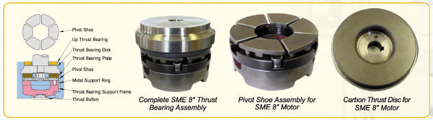
Principle: The Hydrodynamic thrust bearing transmits the rotating shaft's axial thrust load to the frame of the motor, which is mechanically supported in the well.
The axial thrust load is transmitted through the bearing on a self-renewing film of lubricant, which is water in most SUBMERSIBLE MOTOR ENGINEERING motors. The pressure in the fluid film supports the load without the thrust disc or pivot shoes making contact.
Theory: Due to viscosity, fluids tend to stick to surfaces, and in the case of Kingsbury type thrust bearings, they rely on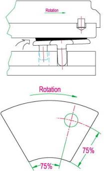 the fluid sticking to the surface of the rotating thrust disc. The fluid is dragged circumferentially as well as being thrown outwards by the rotating disc. At the leading edge of the pivot shoes, a continuous fluid wedge will form. When the right conditions exist the wedge will produce sufficient lift to create a physical separation between the thrust bearing disc and the face of the pivot shoe. At this point a true fluid film (TFF) is said to exist.
TFF is essential for the successful operation of the thrust bearing. When the bearing is operating correctly there is no contact at all between the disc face and the face of the pivot shoes. The only time there is contact is when the motor is stopping or starting. This brief contact period means there should be only negligible wear between the faces - and no wear while the motor is operating.
The adjacent sketch shows how the pivot shoe tilts over and allows the fluid to be forced between the carbon thrust disc and the face of the pivot shoe by a combination of rotational drag and centrifugal force. The pivot point should be spherical which allows the shoes to rotate or pivot so that the fluid can form a wedge. The shoes need to be loosely constrained while still free to pivot.
The carbon thrust bearing drags the fluid around in a circular direction, but this fluid also experiences a centrifugal force, which is pulling the fluid towards the circumference of the bearing. The combination of these 2 forces means that the fluid is circulating and going outwards at the same time and it has been found that the peak pressure point is somewhere beyond the centre in the direction of rotation. Quite often this is assumed to be on the face of the pivot shoe approximately 75% across the face of the pivot shoe and 75% out towards the circumference. This is known as the 75/75 Rule in Thrust Bearing design and is where the bearing has peak loading, minimum film thickness, and high temperatures. If the thrust bearing only operates in one direction it is common to offset the pivot point so it is nearer to the 75/75 point.
From the Pressure Distribution Curve it can be seen that peak load is not on the centre line of the pivot shoe, but offset in the direction of rotation.
Issues that need to be considered during the design of a hydrodynamic thrust bearing are maximum total loads, load per mm2 on the bearing surface, number of shoes, thrust disc surface speed, fluid viscosity, and maximum allowable fluid temperature. Hydrodynamic thrust bearings commonly have 6 or 8 pivot shoes because of the difficulty of ensuring that all the shoes share the load evenly. More shoes increase the likelihood of uneven loading because of variations in dimensions due to mechanical tolerances.
The thrust-bearing disc transmits the axial thrust load from the rotating shaft (rotor) through the fluid film to the stationary pivot shoes. A typical film thickness under rated thrust load can be 0.03 mm for a high performance thrust bearing.
Other Issues:
Cleanliness. It is very important that the inside of the motor is very clean with no loose material that could circulate in the water. All the Thrust Bearing components should be ultrasonically cleaned prior to assembly as any lapping paste that is not removed from the pivot shoes or the carbon disc will tend to circulate in the fluid. (Pivot shoes should also be demagnetised after grinding and lapping to ensure they do not attract any magnetic particles that might be present. Any foreign material, larger than the film thickness, that passes through the thrust bearing can damage the surface of the carbon surface of the thrust disc and can get imbedded in the surface of the carbon. (It is unlikely to scratch the face of the pivot shoes as these are specially hardened). Any water that is used to top up inside the motor should also be clean, but most tap water is fine.
Surface Finish and Tolerances. It is essential that the surface of the carbon thrust-bearing disc be machined flat and exactly perpendicular to the shaft with negligible run out on the face. The surface must be lapped to give a very smooth flat finish. The surface of the face of the pivot shoes is also ground and lapped to give a very smooth flat finish, and in addition the height of each pivot shoe in a set must be identical and the base of the pivot leg must be spherical so that the pivot shoes are free to pivot and share the load equally. Due to mechanical tolerances there will always be some variations in dimensions, but in general they should be tightly controlled. The design of the SUBMERSIBLE MOTOR ENGINEERING thrust bearing allows the whole thrust bearing assembly to swivel on the thrust button, which also allows the pivot shoes to share the load more evenly.
Speed of Rotation. It is important that thrust bearings are not operated at low speeds, or speeds well below their design operating speed. At the low speeds there will not be enough rotational speed to force the fluid through between the pivot shoe faces and the thrust disc, so the faces will be in contact as the motor rotates and this will lead to wear and heat generation due to friction. This can be a problem when using VVVF drives or soft starters and we recommend a maximum run up time of 4 seconds. It can also be a problem when the motor is switched off as the water in the column could flow back down through the pump in the reverse direction and cause the pump to rotate which will cause the bearing to rotate at a low speed. In most installations a check valve is fitted just above the pump, which will prevent this from happening, even though it is quite common for a small drain hole to be drilled in the check valve to allow the column to drain slowly after the motor/pump is switched off.
Temperature. The temperature of the fluid inside the motor can have a big influence on the performance of the bearing because the viscosity of the fluid will change with temperature and if the water temperature gets close to boiling point the water will loose all it’s viscosity and the bearing will fail. Because the TFF will not be maintained, sliding contact between surfaces will occur and wear will increase.
Lubrication and Film Thickness. For the bearing to operate properly the lubricating fluid must always be present between the carbon thrust disc and the faces of the pivot shoes. This fluid heats up as it passes through between the 2 faces of the bearing and needs to be cooled and recirculated before it passes through the bearing again. The fluid entering the bearing should always be reasonably cool before it enters between the bearing faces so it can cool the bearing as it passes through.
Shock Loading. This can occur when a pump starts to cavitate. These bearings will tolerate some shock loading, provided the peak shock load does not exceed the maximum load the bearing can take. If the maximum load is exceeded the carbon will make contact with the pivot shoes and high wear and high temperatures will result. In extreme cases the carbon will be pounded onto the pivot shoes and will then disintegrate.
Load distribution to the pads/pivot shoes. It is essential to ensure that the height of each pivot shoe is exactly the same so that each pivot shoe shares the load evenly. If one shoe is shorter than the other shoes then it will have a bigger gap between the face and the carbon and will not carry as much load as the other shoes. Likewise if one shoe is higher than the other shoes it will tend to carry a much higher load than the other shoes. (Please note that even if the load is not exactly evenly distributed across all the shoes in the thrust bearing it will still work, because all SUBMERSIBLE MOTOR ENGINEERING bearings are very conservatively rated).
Pressure Distribution in the film I Flow Requirements across the bearing. As the thrust load increases the pressure in the gap between the pivot shoes and the carbon will reduce. Any small scratches or indentations in the surface of the pivot shoes or the carbon will reduce the load carrying capacity, as some of the pressure in the fluid will be dissipated into these “voids”. It is essential that fluid inside the motor is free to circulate through the bearing and mix with the fluid around the bearing to dissipate the heat generated in the bearing.
Power Losses. As the thrust load increases on the bearing the power loading on the motor will increase. There is a direct linear relationship between the power consumed in the bearing and the thrust load. Typically for a 6 shoe 8” SUBMERSIBLE MOTOR ENGINEERING thrust bearing with 3000 Kg of “down thrust” the extra power required from the motor is 900 watts. This power is dissipated in heating the fluid and bearing surfaces.
Testing Thrust Bearings:

SUBMERSIBLE MOTOR ENGINEERING have recently commissioned a new Thrust Bearing Test rig, which will allow us to test different bearing designs and different materials, especially for the thrust disc. We recently tested a standard 6 shoe 6” bearing for 120 hours at 2500 kg and found no measurable wear on the face of the thrust disc or on the face of the pivot shoes. The load was increased in steps until the bearing failed at 4620 kg load. We rate this bearing at 2270 kg in a standard 6” motor.
Overload Settings and Temperature Protection
At SUBMERSIBLE MOTOR ENGINEERING we are committed to assisting our clientele to improve their level of expertise and understanding of the protection for submersible motors.
It seems to us that most electricians set the current overload protection about 5% above the nameplate full load current, regardless of the current the motor is actually drawing when it is operating, which will not protect the motor if it is only loaded to 70% of the nameplate current.
After the first few days of operation, submersible pumps and motors, tend to settle down and draw the same current for days, months, years - until something changes. Sometimes the load will fluctuate a little with irrigation applications, or supply voltage variations, etc., but generally the current will not vary.
In our opinion to protect the motor and pump the owner/operator needs to know when something changes so they can investigate that change. Quite often the reason for the change can be found on the surface and fixed very easily. A recent example we know about was a diesel generator that had sped up and was generating at 55Hz instead of 50Hz.
SUBMERSIBLE MOTOR ENGINEERING recently supplied a 300Hp 4P 14” motor with a nameplate current of 431 amps and the actual duty point current was 320 amps. The site electrician decided to set the current overloads to trip the motor at about 430 amps, which they did, after there had been a catastrophic failure. The motor only ran for 20 hours, and the pump and motor were then out of action for 4 weeks while everyone involved argued about what had happened and then agreed to get the motor fixed, which involved rewinding and rebuilding. We are certain that if the overloads had been set to 330 amps they would have tripped and alerted the owner that there was a problem. There is a reasonable chance that the reason for the trip could have been identified and fixed. Failing that, the motor could have been operated and monitored very closely. If the current had kept rising it would have indicated that something was seriously wrong and the motor and pump could have been pulled before there was a catastrophic failure. This would have reduced the down time that the pump was out of service, and reduced the costs to everyone involved.
This motor was also fitted with 4 x PT100 temperature detectors which were not connected and therefore not protecting the motor.
All SUBMERSIBLE MOTOR ENGINEERING motors are supplied with 1 PT100 in the DE Windings as standard and all motors of 100Hp or more are fitted with 4 PT100s as standard and customers are free to order additional PT100s in smaller motors, if they want.
At SUBMERSIBLE MOTOR ENGINEERING we confidently believe that a combination of “Quick Trip” current overloads and PT100 temperature monitoring will give end users a lot of comfort that their motors are operating properly, and if something does change, alert the end user that there is a problem before it is catastrophic.
There are 2 recent examples that we are aware of, where temperature monitoring has more than paid for the additional cost of installation.
A 60Hp 8” High Temperature oil filled motor was supplied to the Water Corporation of WA for a bore that has a big problem with Iron Bacteria growth. Typically the growth is about 10mm thick after 3 months of operation and most standard motors have to be pulled up and cleaned every 3 months to prevent them over heating.
The new SUBMERSIBLE MOTOR ENGINEERING motor has 4 PT100s fitted and monitored and the Water Corporation can monitor the temperature in the motor, which has settled down at about 76 Deg.C. The motor has been operating for about 9 months and there is no plan to pull it up until a problem develops. In theory the winding temperature can be allowed to increase to 120 Deg.C. before we would consider that it is too hot. (The oil in this motor has been specially approved by the West Australian Health Department as safe to use in drinking water). A 250Hp 4 Pole 14” motor on an offshore oil platform, was fitted with 4 PT100s, which were all being monitored continuously. This motor was subjected to very high thrust loading, possibly as high as 7000 Kgs. Due to a misunderstanding during testing each of the valves in the system were closed one at a time while the motor was still running. Luckily the Thrust Bearing PT100 detected a rapid increase in temperature from 46 Deg.C. to 95 Deg.C. and shut the motor down before there was any catastrophic damage. It was decided to check the condition of the thrust bearing after this episode and it was found to be damaged and was replaced. In summary we urge all our customers to try to ensure that the current overload protection is set just above the steady state current during operation, and to install PT100 monitoring equipment, which we can supply, and advise on at a very attractive cost.
SUBSEA/ROV MOTORS:

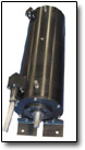
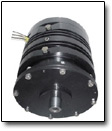
Silvercrest/SME build and repair ROV submersible motors for all subsea applications. We design, manufacture, and supply, submersible electric motors for all SUBSEA and ROV, SUBSEA equipment, also for any special purpose submersible electric motor requirements.
Silvercrest/SME offer SUBSEA electric generators for Tidal Power Generation.
We repair and rewind large high voltage (500kW, 6600V) submersible electric motors.
High Temperature Submersibles in 6-inch to 20inch frames suitable for operation in ambient temperatures of 75 Deg. C.
![]()
Supply High Voltage water filled submersible motors (3300V, 4160V and 6600V)
![]()
Supply Upgraded Temperature Monitoring units, with new improved user-friendly parameter settings.
![]()
Manufacture Subsea and ROV motors suitable for depths of 4000M.
![]()
Manufacture Subsea Electric Generators for Tidal Generation.
Induction Generators or slow speed Permanent Magnet Synchronous Generators unto 500kW.
SUBMERSIBLE MOTORS and PUMPS.
We offer a wide range of electric submersible motors with matched hydraulic and water pumps.
We have our own submersible motors that are drop-in replacements for most of the popular models in use today.
We can supply ROV HPU submersible motors from 30kW to 250kW, trenching HPU submersible motors from 100kW to 500kW, trenching jetting pumps, plough HPU submersible motors, plough jetting pump sets, turbine and centrifugal water pumps, and hydraulic pumps (Rexroth A7 and A10 series, Sauer 90 series and Kawasaki KV3 series).
We offer AC thrusters as direct replacements to existing DC thrusters from 1kW to 50kW in size.
Silvercrest/SME design and build specialized Submersible ROV motors for use SUBSEA in the offshore industry. These motors are usually made to order and vary from 1kW to 600kW, from 400 to 6600 Volts, 50 or 60 Hz, 2 Pole, 4 Pole, 6 Pole and 8 Pole.
We can repair, rewind, rebuild, and redesign any ROV submersible electric motor.
Silvercrest/SME design and manufacture specialized motors for use on SUBSEA equipment used in the offshore industry.
There are two common methods of construction - stainless steel construction or Marine Grade aluminium that is Black anodized to resist corrosion. We can also offer motors manufactured from Duplex and Super Duplex stainless steel.
Our subsea motors are usually oil filled and pressure compensated. The common operating voltages are 400 volts, 3300 volts, 4160 volts and 6600 volts (even for small 5kW motors).
Our motors operate at depths down to 4000 metres, or deeper by special request.
Silvercrest/SME manufacture complete submersible electric motors, motor-pump sets, and ROV HPU.
We offer submersible motor rewinding / rebuilding /electrical conversion / and original construction modification.
SME can repair and completely rebuild most submersible electric motors (for example: Alstra, Aturia, Bamsa, B. J., Elmaksan, Exodyne/EEMI, G.E., Hayward Tyler, Hitachi, Mercury, Oddesse, Pleuger, Saer, S.M.E., Subteck, Sumo, Sun Star, U.S.).
Company Profile.
Silvercrest/SME manufactures new Submersible and ROV Motors. SME also services and repairs all brands of Submersible and ROV Motors. Including Hitachi, Pleuger, Grundfos, Mercury, Byron Jackson, Haywood Tyler, and Franklin. Our business is to manufacture, supply and service Submersible Electric Motors, Subsea and ROV motors. With a compliment of 30 service orientated staff members, we have the ability to service and technically support all makes and models of Submersible Electric Motors at our Maddington, Perth facility. Our sales department, with a total of 75 years experience in the Submersible and Electric motor business, are happy to assist with any enquiries on the purchase of Submersible Motors, HPU, and motor-pump sets, ranging from 3.7kw to 1500kw, in various voltages and frequencies.
In our 1200 ft facility, purpose built for manufacture and service of Submersible Electric Motors we offer the following in-house services:
Full Machine Shop capacity.
Voltage Testing through 10,000 volts.
ISO9001 quality assured workshop.
An Overhead crane through 10 ton capacity.
A state of the art Water Pressure Test facility with full international certification.
High POT and Surge Testing.
Full Load / Dyno testing to 250kw of all types of Electric Motors with detailed test reports.
Balancing Facility available, to 250 kg.
SME are a fully integrated manufacturing facility and in addition to our Standard range of submersible motors we also offer the following:
Special Motors for specialist applications.
4 Pole, 6 Pole and 8 Pole motors.
All Stainless Steel or more exotic material construction.
Special Thrust ratings.
Special Lead manufacturing.
NEMA and other couplings in a variety of materials.
Replacement parts of obsolete products.
Technical assistance during Commissioning.
Trouble Shooting.
Repairs to all makes (Oil and Water filled).
Rewinds of all Voltages (200 volt to 6.6kv) with 1 Year Warranty on all rewinds.
Dynamic testing.
Non-Destructive testing.
Welding and Machining.
On site or Factory Based Cable Splicing.
Retro Fitting of Condition Monitoring Equipment.
Modification of existing motors to upgrade them higher specifications.
Refurbishment of ROV motors using more technically advanced materials.
Subsea Electric Generators.
Subsea Generators can be air filled for optimum efficiency and are suitable for depths down to 30 metres.
Induction Generators can be supplied for 2P, 4P, 6P, 8P, and 10P operation, usually close coupled to a gearbox. (The efficiency and PF are poor for Induction Generators with more than 10 Poles).
Permanent Magnet Synchronous Generators can be supplied with very low speeds and 40 poles or 60 poles for nominal 20 RPM operation, which negates the need for a gearbox. These generators can have high efficiency up to 95% and they have unity Power Factor. Because of the number of poles these generators tend to be quite large in Diameter - typically more than 1 metre.
If Subsea Generators are to be used at depths below 30 metres it is recommended that they are oil filled and compensated - but the mechanical losses will be about 3% due to the extra friction from the oil.
DYNAMOMETER LOAD TESTING.
SME type test their motors with a new 300kW water-cooled eddy current dynamometer with full computer control for accurate load testing.
The submersible motors have to be mounted in a tank for external water-cooling during the testing.
Instrumentation measurements are accurate to within 0.5%. The electrical inputs are measured with a Yokogawa 3 Phase Wattmeter. The measured results are stored on a computer, which is linked to the Yokogawa, and performance results can be calculated using the Summation of Losses Method, or the new IEC Input/Output Method. Results can also be calculated to NEMA Input/Output Standards. SME use a diesel generator to generate the electrical supply for the motor tests and can easily test at 50Hz or 60Hz frequencies.
There is a new 500KVA Voltage Regulator to vary and control the output voltage from 0 to 600 Volts, We can also test at 2300, 2850, 3300, and 4160 Volts.
This facility allows SME to supply accurate full Performance Test Reports on specific motors, rather than generalized Routine or Type Test reports.
Silvercrest Submarines.
Tel: England (+44) 1285.760620
E-mail: sales@SilvercrestSubmarines.co.uk
www.SilvercrestSubmarines.co.uk
www.Submarines-Rovs.com
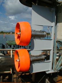