 |
| SUBMARINES SUBMERSIBLES ROVS & SUB-SEA EQUIPMENT |
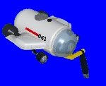
RS-500 RESEARCH SUBMERSIBLE:
/Sub500m%20(MG)/rs%20-2-2.jpg)
The RS-500 is a small lightweight submersible designed for scientific research, underwater filming and subsea survey missions. This submersible operates with a pilot and two passengers, and has an operational depth of 450m (1440ft).
This is a new build with a delivery time of 14 months.
General Technical specification.
LOA 5.0m
Beam 2.2m
Height 2.0m
Draft 1.6m
Dry Weight 5.5 Tons
Payload 250kg
Crew 2/3
Max Operating Depth 450m
Collapse Depth TBA
Max Speed 3 Knots
Endurance 6 to 8 hrs
Hatch Dia TBA
Hull Dia 1.67m
Power Source Lead/acid batteries 23kW/Hrs.
270VDC, 24VDC and 12VDC.
Classification as requested.
Viewports 7 x flat 550mm forward looking
1x360 degree 600mm hatch viewport
Pressure hull Creuselso 38 Steel yield 38kg/mm2
Propulsion 1 x main propulsion 11.5kW, trainable
2 x 3kW vertical fixed
1 x 3 kW bow lateral fixed (see attached details)
Life Support 3 x 13Lt external cylinders @ 200 Bar
CO2 Scrubbers
Monitors for O2, CO2, Temp, Humidity, cabin pressure.
3 x BIBS with full face masks.
Emergency Life Support Minimum of 72 hours per man.
Ballast MBT 650 Lts
Variable Ballast VBT 3 x 50Lts each
Other features (Fixed) 4 x External lights
Electronic Compass
Magnetic compass
Digital depth measurement
Analog depth measurement
Auto heading capability
Auto Depth capability
Turbo propulsion mode*
Obstacle avoidance sonar
Echo Sounder
Underwater Telephone (UQC)
Surface Comms (VHF)
Other features (Modular add on packages) SIT Camera
SIT Replacement camera
Colour 1366 Zoom camera
Stills camera
5 function manipulator (hydraulic)
5 function manipulator (electric)
Mini ROV package
Digital video & data recording package
Other equipment to be rented as required.
Set of technical manuals
On site Pilot Training course and Commissioning
·
Turbo mode allows, at the flick of a switch, the propulsion to be run at 50% overload for a period of 2 minutes. For use in emergency obstacle avoidance.
RS-500 Submarine Description.
Pressure Hull (Control Sphere).
The pressure hull is manufactured from 14mm thick Creuselso 38 steel (yield: 38 kg/mm2). Constructed as a 1672mm diameter sphere with a 700mm aft transfer port, the sphere incorporates 550 mm diameter flat viewports giving a good panoramic view to the front, sides, above and below. Access to the control sphere is via a top rear mounted hatch, which is 600mm diameter with a 25 deg pup piece connected to a 600mm diameter x 175mm deep acrylic section affording 360 degrees of viewing within the sail area.
The main hull sphere contains the primary pilot control and life support control functions.
Transfer Section
The 700mm diameter transfer section leads to an aft machinery spheroid where thruster control, steering control and ballast control machinery is housed.
Fairing
The fairing is manufactured from GRP (Glass Reinforced Plastic) and serves two primary purposes. Firstly, for hydrodynamic purposes to afford optimum performance of the vessel with respect to available thruster power. Secondly to minimize entanglement risk by enclosing the many protruding items of machinery, pipework and cabling associated with the vessels systems. The sail affords a minimum of 1000mm of freeboard with the vessel fully ballasted up on the surface. A rear Plexiglas window in the sail affords a visual of the main lift point just aft of the sail, for use during launch and recovery operations.
Skids
The vessel uses twin tubular skid assemblies longitudinally along the vessel for use in setting down on the deck or seabed. Tubular is used to minimize the dry weight of the vessel. The tubular is vented to allow full flushing and draining of the tubular voids on deck, minimizing the potential for corrosion in a flooded member.
Propulsion and Control
The vessel is powered by 3 x 3kW / 160VAC / 3 PH / 0-50 Hz direct drive, variable speed, bi-directional fixed thrusters in the vertical and bow lateral positions. The verticals are housed in vectored tunnels within the fairing to afford maximum thrust with minimum entanglement potential. The bow lateral is also housed transversally within the bow section of the upper forward fairing section.
The main propulsion is powered by a single 11.5kW / 160VAC / 3PH / 0-50Hz variable speed, bi-directional, trainable thruster, externally mounted on a rudder pedestal at the rear of the vessel. This thruster can train 90 degrees either side of the centre axis of the vessel. All thrusters can be tuned in situ for optimum performance in their respective operating positions under real load conditions. This is an integral part of the systems commissioning procedure carried out by Silvercrest Technicians.
All thrusters are driven by CT, DC/AC invertor controllers with fully programmable digital control. (See attached propulsion spec). The propulsion system incorporates a Turbo function, whereby at the flick of a switch on the pilots console, the propulsion can be operated at 150% full power for a period of 2 minutes in case of maneuvering emergencies such as sudden excessive currents. Thrusters are controlled via a single 3-axis joystick with trim controls in each axis. Steering also includes Auto Heading and Auto Depth capabilities. The pilots control feedback is via flat screen computer monitor readout of all control parameters.
The digital PC based motor controller system allows for specific operational profiles to be tailored to the meet the requirements of the end user. Silvercrest technicians will commission the system on site to optimize the functionality of the system in accordance with the customers needs. (See propulsion spec for further details).
A secondary industrial control computer is dedicated to mission requirements, incorporating digital storage of data, video and stills photography. Redundant analog and digital capacity is included to facilitate extra add on sensors as dictated by the mission profiles. Video tape recording facilities can also be catered for (Spec TBA).
Steering
Steering is controlled using one of the 3 functions incorporated in the 3-axis joystick controller. Joystick steering signals are buffered via the propulsion control computer and fed to the steering servo motor drive controller. When activated, the signal from the electronic compass is also fed into the propulsion control computer, where it is integrated in to the steering control signal to affect Auto Heading control.
Steering is effected primarily by the main aft thruster training in the horizontal axis on an aft mounted rudder pedestal, assisted by the laterally mounted bow thruster. Rotary movement of the rudder pedestal is effected by a top mounted electronically controlled servomotor.
Lateral motion is possible by training the main thruster to one side and mixing bow lateral and forward joystick commands to achieve desired movement.
Depth control
Depth control is affected via a function on the 3-axis joystick. Signals are sent to the propulsion computer where they are buffered and then sent to the vertical thruster motor invertor drive. When activated, an associated digital pressure transducer signal is integrated via a PID loop into the vertical control signal to effect Auto Depth control.
Once the vessel is trimmed using the hard ballast system, the vessel uses two vectored bi-directional thrusters mounted 25 degrees from vertical to effect depth control.
Power
The vessel is powered via two externally mounted 270VDC oil filled battery banks. This Main power is supplied to the Main PDU (Power Distribution Unit) within the machinery space, where it is bussed together to provide the main propulsion power source.
Control and emergency 24VDC battery banks are also located within the same battery box enclosures. Control and emergency power is supplied to the 24VDC Main PDU within the control sphere.
Batteries used are Lead / Acid heavy-duty traction cells immersed in oil for depth compensation. The bank is fitted with an automatic electrolyte top up system for ease of maintenance.
Battery capacity is sufficient to enable 8 hours of operation under normal operating conditions. A Surface to Sub restrained power umbilical capability is an option if required. Alternatively a Hot Connectible Sub-to-Surface capability via emergency umbilical is also an available option.
Lighting and Photography
The vessel incorporates four forward mounted, fixed Halogen or High Power (HP) LED light units for maneuvering purposes. Facilities to power four extra dedicated flood or spotlights for video and still photography. Varied colour temperature HP LED light elements are also available from IR through UV light spectrums.
One Low light SIT replacement camera and one Kongsberg 1366 zoom color CCD camera with remote control.
Two external charging supplies for external strobes and 4 of 24VDC power supplies with controls for external video or stills cameras.
Power supplies and control for two 24VDC electrical pan and tilt units (units can also be supplied subject to client requirements)
Communications
Surface communications are effected using a Marine Band VHF radio within the control sphere. Sub-surface communications are by UWT (Under Water Telephone) operating at 10kHz and 27kHz (or as otherwise specified) in the control sphere. Facilities to power and control externally mounted HPR Transponder/Responder units are also included. Direct hard wire communications connection to the surface via a strain relieved umbilical, or externally floated communications buoy are available optional extras as required.
Life Support
The vessel carries sufficient consumables to effect life support for a mission time of eight hours, plus emergency life support for 72 hours for three crew. Life support equipment includes; CO2 scrubbing, metered O2 feed, O2, CO2, temperature, humidity and barometric monitoring. BIBS (Built In Breathing System) with full-face masks. De-humidification / air-conditioning, water, food, life jackets and standby soda lime storage for 3 persons. An externally releasable Emergency Marker Buoy / EPIRB is mounted within the fairing (Optional. To be specified).
Ballast Control
The vessel incorporates 3 ballast systems; Fixed, Main and Variable.
Fixed: The Fixed ballast system consists of lead ingots distributed within the exostructure to effect neutral buoyancy of the vessel in accordance with certifying bodies documented requirements.
Main: The Main ballast system or (Soft) ballast system consists of a collar of air filled ballast tanks situated within the fairing to provide clearance or freeboard when surfaced, facilitating safe opening of the hatch whilst at sea. The soft ballast can also be used as an emergency surfacing aid.
Variable; The Variable ballast or (Hard) ballast system consists of a pressure resistant tank which can be emptied or filled using a high pressure water pump to adjust the trim of the vessel which may change as a result of changes in payload from mission to mission.
Control of the Main and Variable ballast systems is affected via a pneumatic control panel situated within the control sphere. Externally stored HP and LP air storage cylinders located within the fairing, supply the air needed to effect ballast control. All used air is vented externally via an overboard dump valve, resulting in no cabin pressure change
The externally mounted HP ballast pump is electrically driven. Control for which is also located within the control sphere.
External Attachments
The vessel is designed to operate with a standard fit of an electrical or hydraulic 5-function manipulator, sampling tools, lighting, cameras, depth sounder and obstacle avoidance sonar. It is also designed to accommodate externally mounted modules to meet the further requirements of specific mission profiles.
Please contact us for further details.
SILVERCREST SUBMARINES.
Tel: England (+44) 1285.760620
E-mail: sales@SilvercrestSubmarines.co.uk

![]()